The vertical system of your scope supplies the display system with the Y axis — or vertical — information for the graph on the CAT screen. To do this, the vertical system takes the input signals and develops deflection voltages. The display system then uses the deflection volt ages to control — deflect — the electron beam.
The vertical system also gives you a choice of how you connect the input signals (called coupling and described below). And the vertical system pro vides internal signals for the trigger circuit (described in Section 4). Fig. 4 illustrates the vertical system schematically.
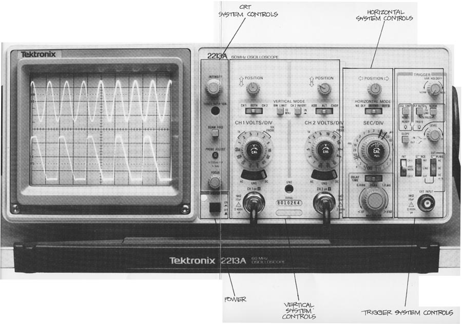
Some of the vertical system controls see the front panel illustration for their locations—are: vertical position, sensitivity, and input coupling.
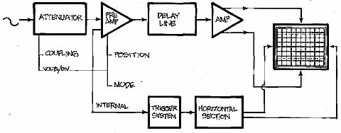
Fig. 4: THE VERTICAL SYSTEM of a Tektronix 2200 Series scope consists of
two identical channels though only one is shown in the drawing. Each channel
has circuits to couple an input signal to that channel, attenuate (reduce)
the input signal when necessary, pre-amplify it, delay it, and finally amplify
the signal for use by the display system. The delay line lets you see the
beginning of a waveform even when the scope is triggering on it.
AMAZON multi-meters discounts AMAZON oscilloscope discounts
Because all 2200s are two-channel scopes, you will have one set of these switches for each channel. There are also two switches for choosing the scope’s vertical display mode and one control that allows you to invert the polarity of the channel 2 signal.
For the exercises in this section, you’ll need a 10X probe like the Tektronix P6122 lox Probes supplied with every 2200 Series scope.
Vertical Position
Your scope’s POSITION controls let you place the trace exactly where you want it on the screen. The two vertical POSITION controls (there’s one for each channel) change the vertical placement of the traces from each vertical channel; the horizontal POSITION control changes the horizontal position of both channels at once.
Input Coupling
The input coupling switch for each vertical channel lets you control how the input signal is coupled to the vertical channel. DC (the abbreviation normally stands for direct current) input coupling lets you see all of an input signal. AC (alternating cur rent) coupling blocks the constant signal components and permits only the alternating components of the input signal to reach the channel. An illustration of the differences is shown in Figure 5.
The middle position of the coupling switches is marked GND for ground. Choosing this position disconnects the input signal from the vertical system and makes a triggered display show the scope’s chassis ground. The position of the trace on the screen in this mode is the ground reference level. Switching from AC or DC to GND and back is a handy way to measure signal voltage levels with respect to chassis ground. (Using the GND position does not ground the signal in the circuit you’re probing.)
Vertical Sensitivity
A volts/division rotary switch controls the sensitivity of each vertical channel. Having different sensitivities extends the range of the scope’s applications; with a VOLTS/DIV switch, a multipurpose scope is capable of accurately displaying signal levels from millivolts to many volts.
Using the volts/division switch to change sensitivity also changes the scale factor, the value of each major division on the screen. Each setting of the control knob is marked with a number that represents the scale factor for that channel. For example, with a setting of 5 V, each of the eight vertical major divisions represents 5 volts and the entire screen can show 40 volts from bottom to top. With a VOLTS/DIV setting of 2 millivolts, the screen can display 16 mV from top to bottom.
If you pronounce the “/” in VOLTS/DIV as “per” when you read the setting, then you’ll re member the setting is a scale factor; for example, read a 20 mV setting as “20 millivolts per division.”
The probe you use influences the scale factor. Note that there are two unshaded areas under the skirts of the VOLTS/DIV switches. The right-hand area shows the scale factor when you use the standard l0x probe. The left area shows the factor for a 1x probe.
Variable VOLTS/DIV
The red CAL control in the center of the VOLTS/DIV switch pro vides a continuously variable change in the scale factor to a maximum greater than 2.5 times the VOLTS/DIV setting.
A variable sensitivity control is useful when you want to make quick amplitude comparisons on a series of signals. You could, for example, take a known signal of almost any amplitude and use the CAL control to make sure the waveform fits exactly on major division graticule lines. Then as you used the same vertical channel to look at other signals, you could quickly see whether or not the later signals had the same amplitude.
Channel 2 Inversion
To make differential measurements (described in Part II), you have to invert the polarity of one of your input channels. The INVERT control on the vertical amplifier for channel 2 provides this facility. When you push it in, the signal on channel 2 is inverted. When the switch is out, both channels have the same polarity.
Vertical Operating Modes
Scopes are more useful if they have more than one vertical display mode, and with your Tektronix 2200, you have several controlled by two VERTICAL MODE switches: channel 1 alone; channel 2 alone; both channels in either the alternate or chopped mode; and both channels algebraically summed.
To make the scope display only channel 1, use the CH 1 position on the left-hand
switch.
To display only channel 2, use the CH 2 position on the left-hand switch.
To see both channels in the alternate vertical mode, move the left-hand switch to BOTH (which enables the right-hand switch) and then move the right-hand switch to ALT. Now you can see both channels since the signals are drawn alternately. The scope completes a sweep on channel 1, then a sweep on channel 2, and so on.
To display both channels in the chop mode, you move the left-hand switch to BOTH and the right-hand one to CHOP In the chop mode, the scope draws small parts of both signals by switching back and forth at a fast fixed rate while your eyes fill in the gaps.
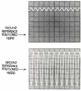
Fig. 5.: VERTICAL CHANNEL INPUT COUPLING CONTROLS let you choose AC and DC input coupling and ground. DC coupling connects the entire input signal
to the vertical channel. AC coupling blocks constant signal components and only connects alternating components to the vertical channel. The GND position
disconnects the input signal and shows you the scope’s chassis ground level.
AC coupling is handy when the entire signal (alternating plus constant
components) might be too large for the VOLTS/DIV switch settings you want.
In a case like this, you might see something like the first photo. But eliminating
the direct component allows you to look at the alternating signal with a
VOLTS/DIV setting that's more convenient as in the second photo.
Both chop and alternate are provided so that you can look at two signals at any sweep speed. The alternate mode draws first one trace and then the other, but not both at the same time. This works great at the faster sweep speeds when your eyes can’t see the alternating. To see two signals at the slower sweeps, you need the chop mode.
If you want to seethe two input signals combined into one waveform on the screen, use BOTH on the left-hand and ADD on the right-hand switch. This gives you an algebraically- combined signal: either channel 1 and 2 added, (CH 1) + (CH 2); or channel 1 minus channel 2 when channel 2 is inverted, (+CH 1) + (-CH 2).
Alternate Sweep Separation
On the 2215A dual time base scope, there is also a sweep separation control: NB SWP SEP. It’s used to change the position of the scope’s B sweep traces with respect to the A sweeps. Using the NB sweep separation in conjunction with the vertical POSITION controls lets you place all four traces (two channels and two time bases) on the screen so that they don’t overlap. (Dual time-base scope measurements are described in Section 9.)
Using the Vertical Controls
Before using the vertical system controls, make sure all the controls are positioned where you left them at the end of the last Section:
• INTENSITY and FOOUS set for a bright, crisp trace;
• trigger SOURCE (A SOURCE on the 2215A) switch on NT and the INT (2215A: A&B INT) switch on CH 1;
• trigger MODE (2215A; A TRIGGER MODE) button on P-P AUTO;
• trigger VAR HOLDOFF control in its extreme counterclockwise position;
• SEO/DIV (2215A: A and B SEC/DIV) switch to 0.5 ms;
• both channel VOLTS/DIV switches on 50 V (10X probe reading);
• both CAL VOLTS/DIV switches in their detents at the extreme clockwise position;
• input coupling levers in GND;
• VERTICAL MODE is CH 1;
• and HORIZONTAL MODE is NO DLY (2215A mode is A). Now connect your 10X probe on the channel 1 BNC connector on the front panel of your scope. (BNC means “bayonet Neill Concelman”; named for Paul Neill, who developed the N Series connector at Bell Labs, and Carl Concelman, who developed the C Series connector.)
Put the tip of the probe into the PROBE ADJ jack. Probes come with an alligator-clip ground strap that’s used to ground the probe to the circuit-under-test. Clip the ground lead onto the collar of the channel 2 BNC connector as shown in Fig. 6.
Use the callouts in this image to remind yourself of the controls locations and follow the directions in Ex. 3 to review the vertical system controls.
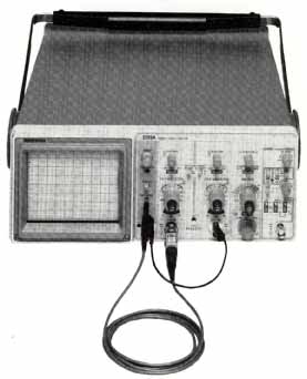
Fig. 6: THE TEKTRONIX P6122 10X PROBE connects to the BNC connector of
either channel 1 (shown) or 2; unlike the photo, the probe’s ground strap
is usually connected to the ground of the circuit you are working on. The
probe adjustment jack is labeled PROBE ADJUST and is located near the CRT
controls on the front panel.
Exercise 3. VERTICAL SYSTEM CONTROLS
Compensating Your Probe 1. Turn on the scope and move the CH 1 VOLTS/DIV switch clockwise to 0.5 V, remember the P6122 is a 10X probe, souse the VOLTS/DIV readout to the right.
2. Switch the channel I input coupling to AC.
3. If the signal on the screen isn’t steady, turn the trigger LEVEL (A TRIGGER LEVEL on the 2215A) control until the signal stops moving and the TRIG‘D light is on. (Use the FOCUS control if you think you can get the signal sharper, and INTENSITY to adjust the brightness.)
4. Next, compensate your probe. There’s a screwdriver adjustment on the compensation box at the base of the probe; turn it until the tops and bottoms of the square wave on the screen are flat. (There’s more in formation about probes and compensation in Section 5.)
Controlling Vertical Sensitivity
1. The probe adjustment signal is a square wave of approximately 0.5 volts, and the scale factor for channel 1 is now a half-volt per division. At this set ting every major division on the screen represents half a volt. Use the channel 1 vertical POSITION control to line up the bottom edge of the waveform with the center graticule line. The tops of the square wave should be just touching the next major division line, proving the probe adjustment signal is approximately 0.5 volts. (Note that the probe adjustment signal is not a critical circuit in the scope; this is why the square wave is approximately 0.5 volts.)
2. Turn the VOLTS/DIV switch two more click stops to the right. The channel 1 scale factor is now 0.1 volts/division, and the signal — still half a volt — is now about five major divisions in amplitude.
3. Turn the CAL VOLTS/DIV control to the left. That will take it out of its calibrated detent position and let you see its effect. Since it reduces the scale factor >=2 1/2 times, the signal should be less than two major divisions in amplitude with this control all the way to the left. If it isn’t exactly that, don’t worry. The variable volts/division controls are used to compare signals, not make amplitude measurements, and consequently the exact range of variation isn’t critical. Return the variable control to its detent.
Coupling the Signal
1. Switch your channel 1 input coupling to GND and position the trace on the center graticule. Switch back to the AC coupling position. Note that the waveform is centered on the screen. Move the CH 1 VOLTS/DIV switch back to 0.5 volts and note that the waveform is still centered around the zero reference line.
2. Switch to DC coupling. The top of the probe adjustment signal should be on the center graticule line and the signal should reach to the next lower major division. Now you can see the difference between AC and DC coupling. AC coupling blocked the constant part of the signal and just showed you a half-volt, peak-to-peak, square wave centered on the zero reference you set at the center of the screen. But the DC coupling showed you that the constant component of the square wave was all negative-going with respect to ground, because in DC, all signal components are connected to the vertical channel.
The Vertical Mode Controls
1. So far you’ve been using your scope to see what channel 1 can tell you, but that’s only one of many possible vertical modes. Look at the trace for channel 2 by moving the scope’s left-most VERTICAL MODE switch to CH 2. The input coupling for channel 2 should still be GND at this point, so what you’ll see is the ground reference line. Line up this trace with the graticule line second from the top of the screen with the channel 2 POSITION control.
2. Now move the lever on the left-hand vertical mode switch to BOTH. That lets you pick one of the vertical modes controlled by the right-hand side vertical mode switch; move it to ALT. You’ve just selected the alternate vertical mode. In this mode, your scope alternates between the signals on channel 1 and 2, drawing one complete sweep on channel 1 first, and then drawing a complete sweep on channel2. You can see this happening when you slow down the sweep speed, so move the SEC/DIV switch left to 0.1 seconds per division. Now you can see the two dots from the AC- coupled channel 1 move across the screen for one sweep. Then the single dot from channel 2 will move across the screen. The point is that in the alternate mode each channel/s drawn completely before the scope switches to the other channel. 3. Turn the SEC/DIV switch back to 0.5 ms and switch to CHOP as your vertical mode. The display looks a lot like the alternate mode, but the way it’s achieved is entirely different. In alternate, you saw that one channel’s signal was completely written before the other started. When you’re looking at slow signals with your scope, that can be a bother because only one trace at a time will be on-screen. In the chop mode, however, the scope switches back and forth very quickly between the two traces so that a little part of each is drawn before going on to the next. When you look at the screen, both signals seem continuous because the scope is “chopping” back and forth at a very fast rate—approximately 500 kHz in the 2200 Series. You can see the chopping if you pick a very fast sweep speed. Move the SEC/DIV switch to 10 p.s. Now the display shows broken lines because of the chopping. CHOP is most useful for slow sweep speeds, and ALT for faster sweeps.
4. Move the SEC/DIV switch back to 0.5 ms. There’s one more vertical mode: ADD. In the add mode, the two signals are algebraically summed (either CH1 + CH2, or CH1 - CH2 when channel 2 is inverted). To see it in operation, move the right-hand VERTICAL MODE switch to ADD. Now you can see the combined signal roughly halfway between where the two separate signals were.