So far you’ve found that the display system draws the wave forms on the screen, the vertical system supplies the vertical in formation for the drawing, and the horizontal system provides the time axis. In other words, you know how the oscilloscope draws a graph; the only thing missing is the “when”: when should the other circuits of your scope start drawing the signal, and when shouldn’t they?
The when is the trigger and it’s important for a number of reasons. First, because getting time-related information is one of the reasons you use a scope. Equally important is that each drawing start with the same “when.”
AMAZON multi-meters discounts AMAZON oscilloscope discounts
Obviously the graph drawn on the screen isn’t the same one all the time you’re watching. If you’re using the 0.05uS SEC/DIV setting, the scope is drawing 1 graph every 0.5uS (0.05 uS/division times ten screen divisions). That’s 2,000,000 graphs every minute (not counting retrace and holdoff times, which we’ll get to shortly). Imagine the jumble on the screen if each sweep started at a different place on the signal.
But each sweep does start at the right time—if you make the right trigger system control set tings. Here’s how it’s done. You tell the trigger circuit which trigger signal to s with the source switches. With an external signal, you connect the trigger signal to the trigger system circuit with the external coupling controls. Next you set the trigger circuit to recognize a particular voltage level on the trigger signal with the slope and level controls. Then every time that level occurs, the sweep generator is turned on. The process is diagrammed in Figure 9.
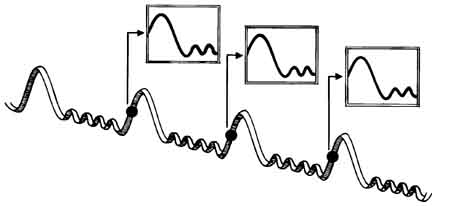
Fig 9. TRIGGERING GIVES YOU A STABLE DISPLAY because the same trigger point
starts the sweep each time. Slope and level controls define the trigger points
on the trigger signal. When you look at a waveform on the screen, you’re seeing
all those sweeps overlaid into what appears to be one picture.
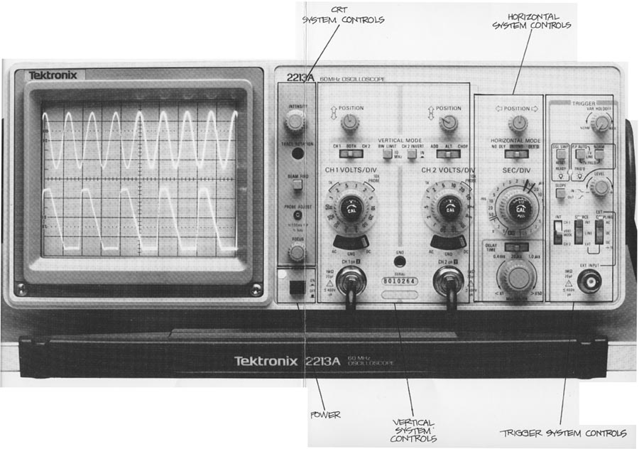
Instruments like those in the Tektronix 2200 Portable Oscilloscope family offer a variety of trigger controls. Besides those already mentioned, you also have controls that determine how the trigger system operates (trigger operating mode) and how long the scope waits between triggers (holdoff).
The control positions are illustrated here. All are located on the far right of the front panel. On the 2213A, the variable trigger holdoff (VAR HOLDOFF) is at the top, and immediately below it's the trigger MODE switch. Below that the trigger SLOPE and LEVEL controls are grouped. Then a set of three switches controls the trigger sources and the external trigger coupling. At the bottom of the column of trigger controls is the external trigger input BNC connector.
On dual time base 2215A scopes, there is a slightly different control panel layout be cause you can have a separate trigger for the B sweep.
Trigger Level and Slope
These controls define the trigger point. The SLOPE control determines whether the trigger point is found on the rising or the falling edge of a signal. The LEVEL control determines where on that edge the trigger point occurs. See Fig. 10.
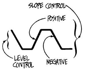
Fig. 10. SLOPE AND-LEVEL CONTROLS determine where on the trigger signal
the trigger actually occurs. The SLOPE control specifies either a positive
(also called the rising or positive-going) edge or on a negative (falling
or negative-going) edge. The LEVEL control allows you to pick where on
the selected edge the trigger event will take place.
Triggering Coupling
Just as you may pick either alternating or direct coupling when you connect an input signal to your scope’s vertical system, you can select the kind of coupling you need when you connect a trigger signal to the trigger system’s circuits. For internal triggers, the vertical input coupling selects the trigger coupling. For external trigger signals, however, you must select the coupling you want:
Coupling |
Applications |
DC |
DC couples all elements of the triggering signal (both AC and DC) to the trigger circuit. |
DC with attenuation |
If you want DC coupling and the external trigger is too large for the trigger system the TRIGGER COUPLING switch to its DC:1O setting. |
AC |
This coupling blocks DC components of the trigger signal and couples only the AC components |
Using the Trigger Controls
To review what you’ve learned about the trigger circuit and its controls (shown schematically in Figure 13), first make sure all your controls are in these positions:
- 0.5 VOLTS/DIV on channel 1 and CAL in its detent position;
- AC vertical coupling;
- CH 1 on the VERTICAL MODE switch;
- 0.5 ms sweep speed and no magnification or variable
- SEC/DIV;
- your trigger settings should be P-P AUTO for MODE, INT for SOURCE, and CH 1 for INT
Turn your scope on with the probe connected to the channel BNC connector and the probe adjustment jack. Use this figure to remind yourself of the control locations and follow the directions in Exercise 5.
Exercise 5. TRIGGER CONTROLS
1. Move the trace to the right with the horizontal POSITION control until you can see the beginning of the signal (you’ll probably have to increase the intensity to see the faster vertical part of the waveform). Watch the signal while you operate the SLOPE control. If you pick +, the signal on the screen starts with a rising edge; the other SLOPE control position makes the scope trigger on a falling edge.
2. Now move the LEVEL control back and forth through all its travel; you’ll see the leading edge climb up and down the signal. The scope remains triggered because you are using the P-P AUTO setting.
3. Turn the MODE switch to NORM. Now when you use the LEVEL control to move the trigger point, you’ll find places where the scope is untriggered. This is an illustration of the essential difference between nor mal and automatic triggering.
4. You can also see the difference between the two triggering modes by using channel 2, even with that channel coupled to GND for ground. Change both the vertical display mode and the INT (2215A; A&B INT) switches to CH 2. With NORM triggering, there’s no signal; with P-P AUTO, you’ll see the baseline. Try it.
5. Without a trigger signal applied to the EXT INPUT BNC connector, it’s impossible to show you the use of this trigger source, but the trigger MODE, SLOPE, and LEVEL controls will all operate the same for either internal or external triggers. One difference between internal and external sources, however, is the sensitivity of the trigger circuit. All external sources are measured/n voltage (say, 150 millivolts) while the internal sources are rated/n divisions. In other words, for internal signals, the displayed amplitude makes a difference. Now change the VERTICAL MODE and INT switches back to CH 1, and switch to the NORM mode. Use the LEVEL control and notice how much control range there is. Now change the CH 1 VOLTS/DIV switch to 0.1 V and use the LEVEL control. There’s more control range now.
6. The alternate-channel/triggering with vertical mode triggering can’t be demonstrated without two unrelated signals on the channels, but you’ll find it useful the first time such an occasion comes up You can take another look at the difference between the normal and auto trigger operating modes. Move the LEVEL control slowly in the NORM mode until the scope is untriggered. Now switch the trigger operating mode to P-P AUTO and note that the wave form is automatically triggered.
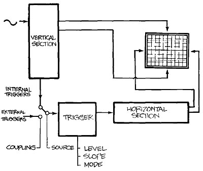
Fig. 13. THE TRIGGER CIRCUITAND ITS CON TROLS are shown in the diagram
above. Trigger source describes whether or not the trigger signal is internal
or external to the scope. Coupling controls the connection of an external
trigger to the trigger circuit. The level and slope controls determine where
the trigger point will be on the trigger signal. And the mode control determines
the operations of the trigger circuit.