Connecting all the measurement test points you’ll need to the inputs of your oscilloscope is best done with a probe like the one illustrated in Figure 14. Though you could connect the scope and circuit-under-test with just a wire, this simplest of all possible connections would not let you realize the full capacities of your scope. The connection would probably load the circuit and the wire would act as an antenna and pick up stray signals—60 Hz power, CBers, radio and tv stations — and these would be displayed on the screen along with the signal of interest.
AMAZON multi-meters discounts AMAZON oscilloscope discounts
Circuit Loading
Using a probe instead of a bare wire minimizes stray signals, but there’s still an effect from putting a probe in a circuit called circuit loading. Circuit loading modifies the environment of the signals in the circuit you want to measure; it changes the signals in the circuit-under-test, either a little or lot, depending on how great the loading is.
Circuit loading is resistive, capacitive, and inductive. For signal frequencies under 5 kHz, the most important component of loading is resistance. To avoid significant circuit loading here, all you need is a probe with a resistance at least two orders of magnitude greater than the circuit impedance (100 M-Ohm probes for 1 M-Ohm sources; 1 M-Ohm probes for 10 k-Ohm sources, and so on).
When you are making measurements on a circuit that contains high frequency signals, inductance and capacitance be come important. You can’t avoid adding capacitance when you make connections, but you can avoid adding more capacitance than necessary
One way to do that's to use an attenuator probe; its design greatly reduces loading. In stead of loading the circuit with capacitance from the probe tip plus the cable plus the scope’s own input, the 10X attenuator probe introduces about ten times less capacitance, as little as 10-14 picofarads (pF). The penalty is the reduction in signal amplitude from the 10:1 attenuation.
These probes are adjustable to compensate for variations in oscilloscope input capacitance and your scope has a reference signal available at the front panel. Making this adjustment is called probe compensation and you did it as the first step in Exercise 3 of Section 2.
Remember when you are measuring high frequencies, that the probe’s impedance (resistance and reactance) changes with frequency. The probe’s specification sheet or manual will contain a chart like that in Figure 15 that shows this change. Another point to re member when making high frequency measurements is to be sure to securely ground your probe with as short a ground clip as possible. As a matter of fact, in some very high frequency applications a special socket is provided in the circuit and the probe is plugged into that.
Measurement System Bandwidth
Then there is one more probe characteristic to consider: bandwidth. Like scopes, probes have bandwidth limitations; each has a specified range within which it does not attenuate the signal’s amplitude more than -3dB (0.707 of the original value). But don’t assume that a 60 MHz probe and a 60MHz scope give you a 60 MHz measurement capability The combination will approximately equal the square root of the sum of the squares of the rise times ( also see Section 10).
For example, if both probe and scope have rise times of 5.83 nanoseconds:
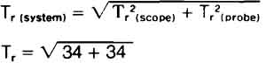
That works out to 8.25 nanoseconds, the equivalent to a bandwidth of 42.43 MHz be cause:
To get the full bandwidth from your scope, you need more bandwidth from the probe. Or you use the particular probe de signed for that instrument. For example, in the case of the 2200 Series scopes and the P6122 10x Passive Probe, the probe and the scope have been de signed to function together and you have the full 60 MHz band width at the probe tip.
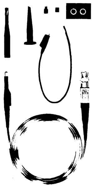
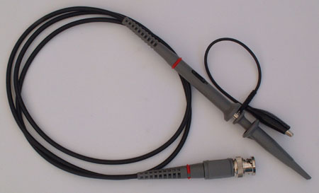
Figure 14. PROBES CONNECT THE SCOPE AND THE CIRCUIT-UNDER-TEST: Tektronix
probes consist of a patented resistive cable and a grounded shield Two
P6122 probes and the accessories pictured above are supplied with every 2200
Series scope. The probe is a high impedance, minimum loading 10X passive probe.
The accessories for each probe (from left to right) are, a grabber tip for
ICs and small diameter leads; a retractable hook tip; and IC tester tip cover;
an insulating ground cover; marker bands; and (in the center) the ground
lead.
Probe Types: Generally you can divide probes by function, into voltage- sensing and current-sensing types. Then voltage probes can be further divided into passive and active types. One of these should meet your measurement requirements.
PROBE TYPES |
CHARACTERISTICS |
1x passive, voltage-sensing |
No signal reduction, which allows the maximum sensitivity at the probe tip; limited bandwidths: 4-34 MHz; high capacitance: 32-112 pF; signal handling to 500 V |
10x/100x/1000x passive, voltage-sensing, attenuator |
Attenuates signals; bandwidths to 300 MHz; adjustable capacitance; signal handling to 500 V (10X), 1 5kV (100X), or 20 kV (1000X) |
active, voltage-sensing, FET |
Switchable attenuation; capacitance as low as 1.5 pF; more expensive, less rugged than other types; limited dynamic range; but bandwidths to 900 MHz; minimum circuit loading |
current-sensing |
Measure currents from 1 mA to 1000 A; DC to 50MHz; very low loading |
high voltage |
Signal handling to 40kv |
Figure 15.: PROBE IMPEDANCE IS RELATED TO FREQUENCY as shown in the table above. The curves plot both resistance (R) and reactance (X) in ohms against frequency in megahertz. The plot shown is for the Tektronix P6122 probe on a 1-meter cable.
Picking a Probe
For most applications, the probes that were supplied with your scope are the ones you should use. These will usually be attenuator probes. Then, to make sure that the probe can faithfully reproduce the signal for your scope, the compensation of the probe should be adjustable. If you’re not going to use the probes that came with your scope, pick your probe based on the voltage you intend to measure. For example, if you’re going to be looking at a 50 volt signal and your largest vertical sensitivity is 5 volts, that signal will take up ten major divisions of the screen. This is a situation where you need attenuation; a lox probe would reduce the amplitude of your signal to reasonable proportions.
Proper termination is important to avoid unwanted ref lections of the signal you want to measure within the cable. Probe/cable combinations de signed to drive 1 megohm (1 M-ohm inputs are engineered to suppress these reflections. But for 50 ohm scopes, 50 ohm probes should be used. The proper termination is also necessary when you use a coaxial cable instead of a probe. If you use a 50 ohm cable and a 1 M-ohm scope, be sure you also use a 50 ohm terminator at the scope input.
The probe’s ruggedness, its flexibility, and the length of the cable can also be important (but remember, the more cable length, the more capacitance at the probe tip). And check the specifications to see if the bandwidth of the probe is sufficient, and make sure you have the adapters and tips you’ll need. Most modern probes feature interchangeable tips and adaptors for many applications.
Retractable hook tips let you attach the probe to most circuit components. Other adaptors connect probe leads to coaxial connectors or slip over square pins. Alligator clips for contacting large diameter test points are another possibility.
But for the reasons already mentioned (probe bandwidth, loading, termination), the best way to ensure that your scope and probe measurement system has the least effect on your measurements is to use the probe recommended for your scope. And always make sure it’s compensated.