You can measure almost any thing with the two-dimensional graph drawn by an oscilloscope. In most applications the scope shows you a graph of voltage (on the vertical axis) versus time (on the horizontal axis). This general-purpose display presents far more information than is available from other test and measurement instruments like frequency counters or multimeters. For example, with a scope you can find out how much of a signal is direct, how much is alternating, how much is noise (and whether or not the noise is changing with time), and what the frequency of the signal is as well. Using a scope lets you see everything at once rather than requiring you to make many separate tests.
Most electrical signals can be easily connected to the scope with either probes or cables. And then for measuring non- electrical phenomena, transducers are available. Transducers change one kind of energy into another. Speakers and microphones are two examples: the first changes electrical energy to sound waves and the second converts sound into electricity Other typical transducers can transform mechanical stress, pressure, light, or heat into electrical signals. You can see that given the proper transducer, your test and measurement capabilities are al most endless with an oscilloscope.
AMAZON multi-meters discounts AMAZON oscilloscope discounts
Making measurements is easier if you understand the basics of how a scope works. You can think of the instrument in terms of the functional blocks illustrated in Figure 1: vertical system, trigger system, horizontal system, and display system.
Each is named for its function. The vertical system controls the vertical axis of the graph: any time the electron beam that draws the graph moves up or down, it does so under control of the vertical system. The horizontal system controls the left to right movement of the beam. The trigger system determines when the oscilloscope draws: it triggers the beginning of the horizontal sweep across the screen. And the display system contains the cathode-ray tube, where the graph is drawn.
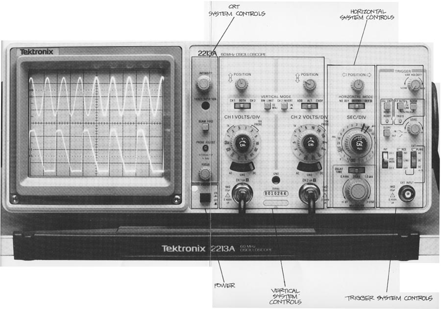
This part of the primer is divided into Sections for each of those functional blocks. The controls for each block are named first, and you can use this illustration of a Tektronix 2213A front panel at the back of the primer to locate them on your scope. Next the controls and their functions are described, and at the end of each Section there are hands- on exercises using those controls.
The last Section in this section describes probes. When you finish reading these five sections, you’ll be ready to make fast and accurate oscilloscope measurements.
But before you turn on your scope, remember that you should always be careful when you work with electrical equipment. Observe all safety pre cautions in your test and measurement operations. Always plug the power cord of the scope into a properly-wired receptacle before connecting your probes or turning on the scope: use the proper power cord for your scope, and use only the correct fuse. Don’t remove the covers and panels of your scope.
Now use the front panel illustration so that it's visible as you read. Use the front panel illustration and follow Exercise 1 to initialize (set in standard positions) the scope controls. These standard settings are necessary so that as you follow the directions on these pages, you’ll see the same thing on your scope’s CRT as is pictured or described here.
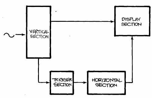
Fig. 1: THE BASIC OSCILLOSCOPE in its most general form has only four functional
blocks: vertical, horizontal, trigger, and display systems (and sometimes,
sections). The display System is also sometimes called the CRT (for cathode-ray
tube) section.
Exercise 1. INITIALIZING THE SCOPE
Use the figure and above callouts to locate the controls mentioned here.
1. DISPLAY SYSTEM CONTROLS: Set the INTENSITY control at midrange (about halfway from either stop). Turn the FOCUS knob completely clockwise.
2. VERTICAL SYSTEM CONTROLS: Turn the channel 1 POSITION control completely counterclockwise. Make sure the left-hand VERTICAL MODE switch is set to CH 1. Move both channel VOLTS/DIV switches to the least sensitive setting by rotating them completely counterclockwise. And make sure the center, red CAL controls are locked in their detents at the extreme clockwise position. Input coupling switches should be set to GND.
3. HORIZONTAL SYSTEM CONTROLS: Make sure the HORIZONTAL MODE switch is set to NO DLY for no delay. (If you’re using a 2215A, move the switch to the A sweep position.) Rotate the SEC/DIV switch to 0.5 millisecond (0.5 ms). Make sure the red CAL (variable) switch in the center of the knob is in its detent position by moving it completely clockwise. And push in on the CAL switch to make sure the scope is not in a magnified mode.
4. TRIGGER SYSTEM CONTROLS: Make sure the CAL HOLDOFF control is set to its full counterclockwise position. Set the trigger MODE button (2215A: A TRIGGER MODE) on P-P AUTO. And move the trigger SOURCE switch (A SOURCE on a 2215A) to INT (internal) and the INT selection switch (A&B INT on a 2215A) to CH1.
After following the steps in Exercise 1, you should plug your scope into a properly-grounded outlet and turn it on. With a Tektronix 2200 scope, there’s no need to change the scope’s power supply settings to match the local power line; the scopes operate on main power from 90 to 250 VAC at 48 to 62 Hz.