The oscilloscope draws a graph by moving an electron beam across a phosphor coating on the inside of the CAT (cathode- ray tube). The result is a glow for a short time afterward tracing the path of the beam. A grid of lines etched on the inside of the faceplate serves as the reference for your measurements; this is the graticule shown in Fig. 2.
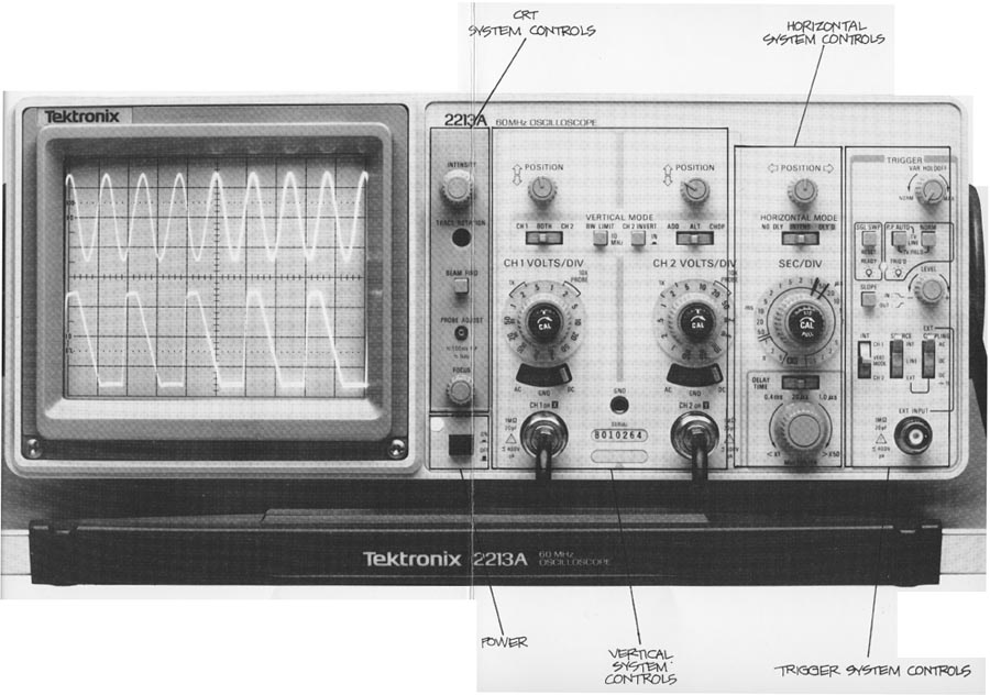
Common controls for display systems include intensity and focus; less often, you will also find beam finder and trace rotation controls. On a Tektronix 2200 Series instrument they are all present, grouped next to and on the right of the CRT. At the top of the group is the intensity control. The TRACE ROTATION adjustment is under that, and then the beam finder (BEAM FIND). Under the probe adjustment jack is the focus control. The functions of these controls are described below and their positions on the Tektronix 2213A Portable Oscilloscope are illustrated below.
AMAZON multi-meters discounts AMAZON oscilloscope discounts
Beam Finder
The beam finder is a convenience control that allows you to locate the electron beam any time it’s off-screen. When you push the BEAM FIND button, you reduce the vertical and horizontal deflection voltages (more about deflection voltages later) and over-ride the intensity control so that the beam always appears within the 8 x 10-centimeter screen. When you see which quadrant of the screen the beam appears in, you’ll know which directions to turn the horizontal and vertical POSITION controls to reposition the trace on the screen for normal operations.
Intensity
An intensity control adjusts the brightness of the trace. It’s necessary because you use a scope in different ambient light conditions and with many kinds of signals. For instance, on square waves you might want to change the trace brightness to look at different parts of the waveform because the slower horizontal components will al ways appear brighter than the faster vertical components.
Intensity controls are also useful because the intensity of a trace is a function of both how bright the beam is and how long it’s on-screen. As you select different sweep speeds (a sweep is one movement of the electron beam across the scope screen) with the SEC/DIV switch, the beam ON and OFF times change and the beam has more or less time to excite the phosphor.
On most scopes, you have to turn the intensity up or down to restore the initial brightness. On the 2200 Series scopes, how ever, the automatic intensity circuit compensates for changes in sweep speed from 0.5 milliseconds (0.5 ms) to 0.5 micro-seconds (0.5 micro-sec). Within this range, the automatic circuit maintains the same trace intensity you initially set with the INTENSITY control.
Focus
The scope’s electron beam is focused on the CRT faceplate by an electrical grid within the tube. The focus control adjusts that grid for optimum trace focus. On a 2200 scope, the AUTO FOCUS circuit maintains your focus settings over most intensity settings (0.5 ms to 0.5 micro-seconds).
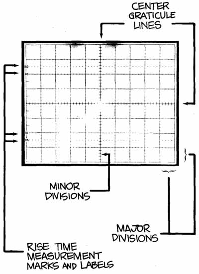
Above: Fig. 2. THE GRATICULE is a grid of tines typically etched or silk-screened
on the inside of the CRT faceplate. Putting the graticule inside — on
the same plane as the trace drawn by the electron beam, and not on the outside
of the glass — eliminates measurement inaccuracies called parallax errors.
Parallax errors occur when the trace and the graticule are on different
planes and the observer is shifted slightly from the direct line of sight.
Though different-sized CRT’s may be used graticules are usually laid
out in an 8 x 10 pattern. Each of the eight vertical and ten horizontal
lines block off major divisions (or lust divisions) of the screen. The labeling
on scope controls always refers to major divisions. The tick marks on
the center graticule hoes represent minor divisions or subdivisions. Since
rise time measurements are very common 2200 Series scope graticules include
rise time measurement markings: dashed lines for 0 and 100% points, and labeled graticule lines for 10 and 90%
Trace Rotation
Another display control you’ll find on the front panel of a 2200 Series instrument is TRACE ROTATION. The trace rotation adjustment allows you to electrically align the horizontal deflection of the trace with the fixed graticule. To avoid accidental misalignments when the scope is in use, the control is recessed and must be adjusted with a small screwdriver.
If this seems like a calibration item that should be adjusted once and then forgotten, you’re right; that’s true for most oscilloscope applications. But the earth’s magnetic field affects the trace alignment and when a scope is used in many different positions — as a service scope will be — it’s very handy to have a front panel trace rotation adjustment.
Using the Display Controls
The display system and its controls are shown as functional blocks in Figure 3. Use Exercise 2 to review the display controls.
Exercise 2. THE DISPLAY SYSTEM CONTROLS
In Exercise 1 you initialized your scope and turned on the power. Now you can find the display system controls labeled on the front panel illustration and use them as you follow these instructions.
1. BEAM FIND: Locate the position of the electron beam by pushing and holding in the BEAM FIND button; then use the channel 1 vertical POSITION knob to position the trace on the center horizontal graticule line. Keep BEAM FIND depressed and use the horizontal POSITION control to center the trace. Release the beam finder.
2. FOCUS: The trace you have on the screen now should be out of focus. Make it as sharp as possible with the FOCUS control.
3. INTENSITY: Set the brightness at a level you like.
4. Vertical POSITION: Now you can use the vertical POSITION control to line up the trace with the first major division line above the center of the graticule.
5. TRACE ROTATION: Use a small screwdriver and the TRACE ROTATION control to rotate the trace in both directions. When you finish, align the trace parallel to the horizontal division line closest to it. (After setting the trace rotation, you may have to use the vertical POSITION control again to align the trace on the graticule line.)
You have used all the scope’s display system controls. If at the end of one of these Sections you’re not going to go on immediately, be sure to turn your scope off.
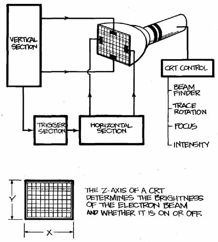
Fig. 3. THE DISPLAY SYSTEM of your scope consists of the cathode-ray tube and its controls. To draw the graph of your measurements, the vertical
system of the scope supplies the Y, or vertical, coordinates and the horizontal
system supplies the X coordinates. There is also a z dimension in a scope;
it determines whether or not the electron beam is turned on, and how bright it's when it’s on.