AMAZON multi-meters discounts AMAZON oscilloscope discounts
Introduction:
There are a number of naturally occurring systems, such as a swinging pendulum, in which there is a periodic interchange between the kinetic energy and the potential energy stored in the system, which results in an oscillatory motion at some clearly defined frequency. In the case of the pendulum, the kinetic energy is the mechanical momentum of the bob as it swings past the mid-point of its travel, and the potential energy is that which is stored in the bob, when it momentarily comes to rest, at the highest point of its swing.
There is an exact electrical analogue to this action in the behavior of a combination of capacitance and inductance in the circuit shown in FIG1a, where the kinetic energy is the flow of current through the inductor, sustained by its associated magnetic field, at the point of zero oscillatory voltage, and the potential energy is that due to the electrical charge accumulated in the capacitor at the peak of the oscillatory voltage swing developed across it.
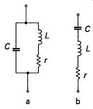
FIG 1 Parallel and series resonant tuned circuits
There must also be some element of energy loss present in any real system, which I have denoted as a resistor r, connected in series with the inductor, al though, in reality, it will be composed of a variety of energy absorbing mechanisms, distributed through the circuit, for which the resistor r is just a mathematically convenient equivalent. (Note: It’s conventional to use the symbol r to represent resistance in series with the inductor, and R, to denote resistance in parallel with it.
Both types of connection can be used to simulate the effect of system losses, and there is a mathematical relationship, shown below, between the resistance values needed to give the same effect in either case.) The value of this type of combination of inductance and capacitance in electronic circuit arrangements is enormous, because of the phenomenon of electromagnetic resonance, which will occur at some specific and unique frequency. At this frequency the dynamic impedance of the parallel tuned circuit shown in FIG1a, becomes extremely high, and at which the impedance of the alternative series tuned circuit layout, shown in FIG1b, collapses to a value equivalent to that of its equivalent series loss resistance, r.
The term 'tuned circuit', which is applied to the circuit layouts shown in FIG1, is used because if the value of the inductor, or, more conveniently, the capacitor, is made variable, the frequency of resonance can be made adjustable, and this was the original method by which radio receivers were tuned to respond to the desired incoming signal.
There is also, in the case of the circuit layouts shown in FIG1, a 'circuit magnification factor', denoted sometimes by the symbol 'm', but more commonly referred to as the 'Q' of the tuned circuit. In a parallel tuned circuit, this term refers to the extent to which an externally induced current, at the resonant frequency of the circuit, will be magnified by the effect of the circuit resonance. In the case of the parallel tuned circuit, this gives the type of frequency response curve shown in FIG2, when an input signal, applied to the circuit of FIG1a, is swept through the frequency of resonance. This diagram also illustrates the effect on the output voltage, and the sharpness of tuning, of different values of circuit Q.
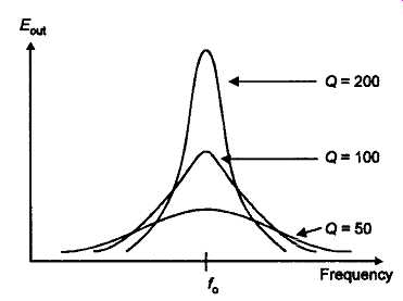
FIG. 2 Frequency curve of single LC tuned circuit.
The importance of this effect, in radio communication, is that it allows a degree of 'selectivity' in the choice of frequency at which a radio receiver will have its maximum sensitivity, to allow the preferential reception of one incoming radio signal rather than another. It also provides, in the design of high frequency oscillators, a convenient means for selecting the frequency at which the circuit will operate.
Calculation of resonant frequency, dynamic impedance and Q
There are a number of methods by which the electrical characteristics of a tuned circuit can be derived, but one of the simplest is to use the relationships which define the electrical impedance of an inductor:
ZL = j w L
and that of a capacitor
Zc=1/(j ω C)
where j denotes the square root of -1, which is a convenient way of representing the 'imaginary', or phase quadrature, components of voltage, current or impedance, and ? is used as a short-hand symbol for frequency in radians/second (= 2 pi f): while L and C are the values of inductance and capacitance in henries and farads respectively.
Using this notation, the impedance of the series circuit of FIG1b will be …
At resonance, when w L = 1(j w C), the terms in the square brackets become zero, the imaginary terms in this equation disappear (which implies that there are no residual quadrature currents, and the circuit looks like a pure resistance), and Similarly, the frequency of resonance can be determined from the relationship w L = 1 /(j w C), which can be rewritten as …
In the case of the parallel resonant circuit, the equation defining its impedance, at any frequency, is:
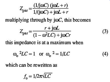
…which gives the same frequency as in the series circuit.
Using the relationships which exist at resonance, as shown in equation (4), allows equation (3) to be expressed in a greatly simplified form, as...
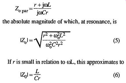
... which is the dynamic impedance of a parallel tuned circuit at resonance, or using the relationships shown in equation (4), 1/C = w0^2 L, the equation can be redrawn as …

The presence of the series resistor somewhat alters the resonant frequency of the circuit, to give a modified value, called the natural resonant frequency, f_n
...from which the presence of circuit losses can be seen to lower somewhat the resonant frequency of the circuit.
However, it must be borne in mind that a simplifying assumption was made in equation (6), that r was small in relation to w L, which implies that the subsequent relationships will only be accurate if this condition is met. In particular, equation (8), which is commonly quoted as an exact relationship, is quite obviously only valid when r^2 /4L^2
…is small in relation to 1/(LC).
Circuit magnification factor Q
This characteristic of a resonant tuned circuit, which is usually simply called the Q (or quality factor) of the circuit--would be, in numerical terms, infinitely high in a resonant circuit which was free from all losses, and which will become lower as the losses increase--determines, as shown above, the sharpness of tuning of the circuit.
High selectivity is advantageous in the sense that it allows greater ease in discriminating between input signals in a radio receiver -- and the associated high Q value will also augment the receiver sensitivity by increasing the size of the signal voltage developed, at resonance, across the tuned circuit. However, there is a snag, in that amplitude modulated radio signals carry their modulation information as a series of sidebands, distributed as sum and difference frequencies on either side of the nominal 'carrier' frequency, so too high a Q value will restrict the amplitude of the sideband signals which will be received.
In a parallel tuned circuit, of the kind shown in FIG1a, Q is defined as the ratio of the current externally applied to the tuned circuit to the internally circulating current, which for any given applied EMF, is the ratio of the dynamic impedance of the tuned circuit to the series resonant impedance: relationships which have been shown in equations (1) and (7).
From these equations …

or, since, at resonance, w0L = 1/(w0C) ...from which the presence of circuit losses can be seen ...
The relationship between the Q of the tuned circuit and the 'half power' (-3dB in terms of the RMS voltage developed across the circuit) points on the frequency response curve of FIG2, is ..
Bandwidth= f_0/Q (Hz) (11)
However, since the bandwidth refers to the actual pass-band between these -3dB points, the actual frequency difference between the frequency of resonance and the -3dB output voltage point on either side of resonance is only half this value, i.e. f_o/2Q. For an actual off-tune frequency difference of f_o/Q the output voltage will be -6dB with respect to that at resonance.
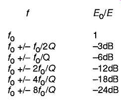
The general equation for the selectivity of a single tuned circuit of the type shown in FIG1a is given by the relationship

... where i0 and E0 are the circulating current within, and the voltage developed across, the tuned circuit at resonance (fQ), and f and E represent the currents and voltages at a frequency, f, somewhat away from resonance. By fitting values into this equation, the frequency response curve for a single parallel resonant tuned circuit can be constructed from the relationships:
Additionally, the relationship between the Q of a tuned circuit and the equivalent series (r) and parallel ( R) loss resistance, at resonance, is given by
R/Q = Q/r (13)
The phase angle between an applied voltage and the circulating current in a parallel tuned circuit undergoes an abrupt transition as the input signal passes through resonance, and is given by the equation ...
Bandpass-coupled tuned circuits
The problem associated with the attenuation of broad cast sidebands by receivers whose selectivity is determined by single tuned circuits, of the kind shown in FIG1a -- a problem which is increased if several such tuned circuits are connected in cascade --can be lessened either by reducing the Q of the individual circuits or, in the case of a series of such circuits, by staggering the frequencies to which the individual circuits are tuned.
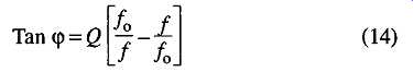
However, a better approach is to combine a pair of tuned circuits as a 'bandpass-coupled' layout, of the kind shown in FIG3. In this, which is the simplest of the possible circuit arrangements usable for this purpose, if the inductors of two identical tuned circuits are brought into proximity with one another, the interaction of the magnetic fields associated with the currents flowing in the inductors will cause a mutual induction of currents from one to the other.
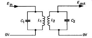
FIG 3 Bandpass coupled pair of tuned circuits
If an oscillatory input signal is swept in frequency through the point of resonance of the tuned circuits, the transfer of energy, by this means, from one tuned circuit to the other- which will be at its greatest at the frequency of resonance because the circulating current through the inductors will be greatest at this frequency -- will cause a reduction in the magnitude of the output voltage peak at this frequency. The extent of the dip which this will cause in the combined frequency response curve will depend on the extent to which the circuits are coupled together, as shown for various coupling factors in Fig, 4. From the point of view of radio reception, the optimum condition is that in which the response has the widest flat topped region, compatible with the avoidance of a significant trough in the output, at resonance. This condition is described as critical coupling, or kc, which has the value ...
kc=1/Q (15)
FIG 4 Frequency response of bandpass coupled pair of tuned circuits for
various coupling factors.
There are a number of other circuit arrangements which will provide bandpass-coupled layouts, shown in FIG5, for which the coupling factors are shown on the diagram.
For optimization of the bandwidth of a receiver using such bandpass-coupled circuits, not only must the correct value of bandpass coupling coefficient be selected, but also the value of the Q of the individual circuits must also be correctly chosen, and adjusted, if necessary, by the use of damping resistors, usually connected in parallel with each part of the tuned circuit.
For very high orders of selectivity, it’s possible to connect a number of high Q bandpass-coupled tuned circuits in cascade, usually in the 'intermediate frequency' amplifier stages in a superhet radio, but in modern practice a quartz crystal filter or some form of electro-mechanical 'ladder' filter will generally be preferred.
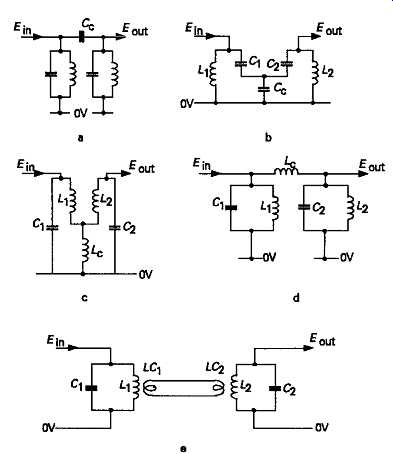
FIG 5 Some common bandpass-coupled circuit layouts.
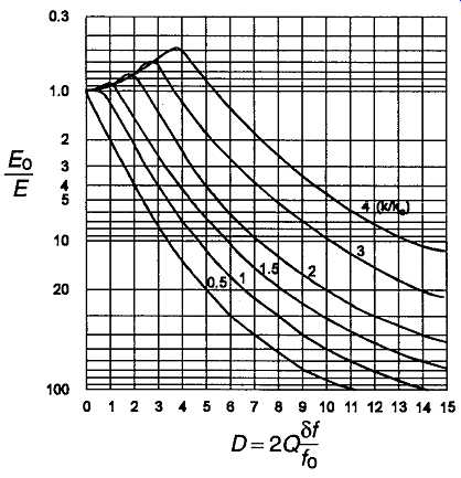
FIG 6 Universal selectivity chart for band pass-coupled tuned circuits
A 'universal selectivity chart' for bandpass-coupled tuned LC circuits is shown in FIG 6. This shows the relationship between the 'skirt' attenuation of a coupled pair of tuned circuits and the degree of off --tuning of the signal, expressed as a proportion (f/f0), of the resonant frequency. It’s apparent from this that the higher the operating frequency (f0), the wider the pass-band, in kHz, for any value of Q and coupling factor.
Quartz crystals and other mechanical resonators
The phenomenon of 'piezo-electricity' was first ob served by the Curie brothers in 1880, and refers to the physical effect that certain materials, usually crystal line in form, will develop an electrical potential on opposed surfaces, when subjected to a mechanical strain. Conversely, in such materials, if an electrical potential is applied to physically opposed surfaces it will result in a small mechanical distortion of the material.
Quartz crystal resonators
Crystalline quartz (SiO2) is one of the materials which exhibits this phenomenon, and it was found that if thin slices of quartz were cut from a crystal, and held between fixed metal electrodes, several very sharply tuned mechanical resonances could be excited, corresponding to the crystal slice 'ringing' in its torsion, compression and shear modes.
The usual mode of operation for high frequency use is for the crystal to be cut and mounted in such a way as to force the excitation of the first order (fundamental frequency) shear mode type of oscillation, shown in FIG7a, though all of the feasible resonance modes can be exploited by the crystal manufacturers .... for specific applications.
The frequency of oscillation of a quartz crystal is given by the approximate relationship .... which would imply a thickness for the quartz slice of only 0.067mm for a 25MHz crystal -- a typical upper limit for crystals operating at their fundamental resonant frequency -- so for higher frequency operation, it’s customary to operate the crystal in a harmonic mode, for which the shear mode vibration pattern is shown in FIG7b.
In contemporary practice, the modes in which quartz crystals are operated are as indicated in TBL. 1.
TBL. 1
Mode Frequency range:
Fundamental 3rd overtone 5th overtone 7th overtone Up to 25MHz 20-75MHZ 60-125MHz 90-175MHz
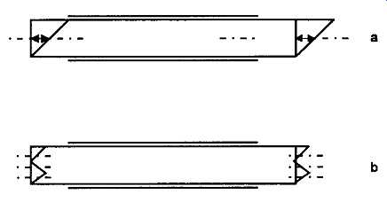
FIG 7 Resonance modes in quartz crystal
The equivalent electrical circuit of a typical quartz crystal resonator is shown in FIG8, in which Co is the intrinsic capacitance of the crystal mounting electrodes and the holder, and will be typically of the order of 3-5pF. R1, C1 and Lt are the so-called 'motional ' parameters of the crystal, and are characteristic of the crystalline homogeneity of the material, and the precision and type of cut. This gives a relationship between impedance and frequency of the kind shown in FIG9. At very low frequencies, the impedance of the crystal is very high, and is due entirely to the stray capacitance of the crystal mounting plates and holder. With increasing frequency, this impedance falls, but remains capacitative, until the frequency of series resonance is reached, when the impedance abruptly plummets to a value equivalent to the loss resistor, R1 (see equation (1) above). Other things being equal, the motional resistance component, R1, decreases linearly with the area of the crystal slice, and is inversely proportional to its thickness, but a practical limit is imposed, at high frequencies, on the area of the slice by the fragility of the crystal.
As in a conventional series resonant LC circuit, the frequency of resonance (fr) is defined quite normally by the equation.
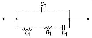
FIG 8 Equivalent electrical circuit of quartz crystal resonator
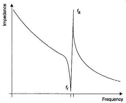
FIG 9 Resonance and anti-resonance modes in quartz crystal resonator; Frequency:
However, at a frequency slightly above this value, the motional inductance component of the crystal will also allow the crystal to resonate with the holder capacitance, C0, in a parallel, or 'anti-resonant', mode (fa). This gives a high impedance peak in the impedance curve, at a frequency defined by the relationship...

The width of the region between these two resonant frequencies, where the crystal presents an inductive impedance, is given by ...
The frequency of resonance of a quartz crystal will be influenced by the size of any external parallel or series connected capacitor, CL, which allows some adjustment of the actual operating frequency. This modified operating frequency, of the crystal,^, will then be defined by ...
...and the crystal will be calibrated by its manufacturers for some specified load capacitance, usually on the assumption that the crystal will be operated in its normal series resonant mode, with an external circuit which will give a near-zero value of phase shift at the operating frequency.
Modern crystal resonators offer extremely high values of Q -- in the range from 50,000 to 2,000,000 -- due to the combination of relatively low levels of internal losses in the crystal and its mounting, giving an effective value for Rx in the range 12-200 ohms, associated with high values of Lx -- in the range 100 2000mH -- and exceedingly low values for C1 -- typically 0.1 -- 5fF -- for crystals resonating in their fundamental mode at 10MHz.
Very high Q values are useful in quartz crystal oscillators, in maintaining a high precision in the frequency of operation, purity of waveform, and good signal/noise ratios. However, the 'activity' of a given crystal -- a measure of the ease with which it will oscillate -- bears an inverse relationship to Q. It may therefore prove more difficult in practice to cause circuits using very high Q crystals to oscillate, even with an appropriately chosen design, and if the external loop gain is increased to make sure of oscillation, care must then be taken to ensure that the input drive power does not exceed the makers recommended limits, to avoid damage to the crystal or excessive frequency drift due to heating. Typical maximum input drive powers recommended for quartz crystal oscillators usually range from a few milliwatts for a general purpose system down to a few microwatts where the crystal is used in a precision frequency reference.
The natural resonant frequency of all quartz crystal resonators is somewhat temperature dependent, an effect which is greatly influenced by the angle at which the slice is cut from the bulk crystal. A commonly employed type of cut, which exhibits a very low degree of thermal drift, around a median temperature of 20°C, is called the 'AT'. The relationship between cutting angle and temperature coefficient for such an AT cut crystal, is shown in FIG10.
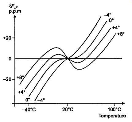
FIG 10 Effect of cutting angle in an AT cut crystal on temperature coefficient
Quite apart from their value as precise and stable frequency defining components for oscillator circuits, the sharply defined notch in the impedance curve of a quartz crystal resonator allows the design of narrow pass-band filters for use in radio receivers. The simplest circuit layout of this type is that shown in FIG11a, where the effect of the shunt capacitance of the crystal, Yl9 is phased out by a variable capacitor, CVl9 in an anti-phase connected limb in the circuit, to give a resultant frequency response of the kind shown in FIG11b.
A modification to this layout to give band-pass characteristics is shown in FIG12a, which em ploys two crystals, Y1 and Y2, whose resonant frequencies are slightly different, to give the frequency response curve shown in FIG12b.
Ladder and Surface Acoustic Wave filters
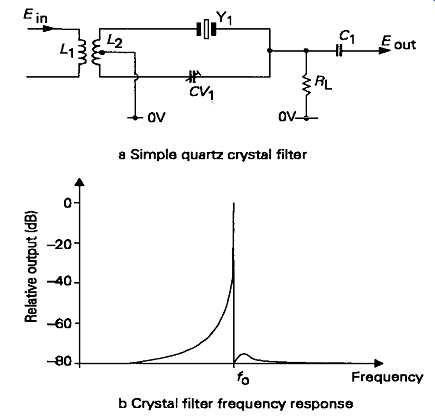
FIG 11 --- a. Simple quartz crystal filter; b. Crystal filter frequency
response
The quartz crystal type of bandpass filter is only really appropriate for use where relatively narrow pass-band widths are required. For wider bandwidths, other techniques are more suitable, of which the two most widely used are the series resonator ladder filter, and the surface acoustic wave (SAW) filter types. Of these, the ladder filter consists of a stack of piezo-electric ceramic disks, which are electromechanically resonant in their fundamental radial mode, and which are mounted in a suitable metal screening tube, as a string of up to 19 elements, so that they are electrically connected but mechanically and acoustically isolated.
Because of their series connection, stray capacitance leakage effects are small, and stop-band rejection levels of better than -80dB are feasible in the 455kHz radio receiver IF pass-band.
In operation, this type of filter behaves like a string of bandpass coupled parallel resonant tuned circuits, whose pass-band is determined by their Q and coup ling coefficient, and their skirt attenuation rate by the number of stages connected in series.
Surface acoustic wave (SAW) type filters
These devices, sometimes referred to as 'inter-digital filters' because of their method of manufacture, exist in two basic forms, the 'transversal', in which a 'travelling wave' is launched along the surface of a strip of piezo-electric material, and the 'resonant' type, in which the electrical excitation is used to produce a sharply tuned 'standing wave' pattern.
(A useful general description of these types of component is given by R. J. Murray and P. D. White (Philips Research Laboratories) in Wireless World, March and April, 1981.) Transversal types The transversal 'T-type' filter came into widespread use in the late 1960s because of the requirements of television and FM radio receivers. Both of these applications required wide, substantially flat topped selectivity curves for the receiver IF (intermediate frequency) amplifier stages -- which would be up to 7MHz for a 45MHz TV IF amplifier, and up to 300kHz in a 10.7MHz FM IF stage.
Although this type of pass-band can be provided by a suitably tuned series of shunt resistor damped band pass coupled tuned circuits, it’s an expensive approach, especially in terms of the labor required to adjust the tuning of the individual circuits, and the SAW T-type filter allowed great manufacturing economies to be made in this respect.
In the case of the T-type (travelling wave) design, the piezo-electric effect is used to launch a mechanical ripple along the surface of a flat strip of suitable material. This is done by depositing an interlaced pattern of electrically conductive stripes on the surface of the strip, as shown, schematically, in FIG13.
If the pattern of the conductors is accurately deposited on the surface of the slice -- a task which is similar to, but, in practice, rather less demanding than, the similar processes performed in the manufacture of integrated circuits -- then if an electrical signal, at an appropriate frequency, is applied to the input (transmitting) group of conductors, the mechanical surface ripple which it causes will be propagated along the slice, and will, in turn, generate an electrical output when it passes under the output (receiving) group of electrodes.
The pass-band characteristics of this layout arise because the signal has effectively been made to pass through a series of delay paths, both at the transmitter and receiver ends of the strip, from which the outputs are added together. In the 'pass' band, these signals will add constructively, while in the 'stop' band they will tend to cancel. By careful choice of the inter-digital spacings, and the extent of the interleaving of the individual digits, it’s possible to generate flat topped transmission curves for these filters of the type shown in FIGs 14 and 15. As in the case of the examples shown, these filters are widely used in TV and FM radio receivers, because they are inexpensive, and don’t require frequency tuning following installation.
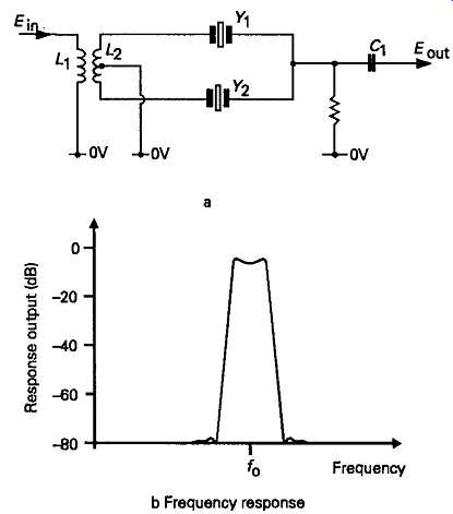
FIG12 Band-pass crystal filter
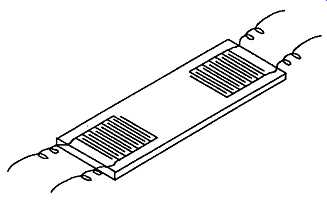
FIG13 T-type surface acoustic wave filter
Some of the low cost filters of this type use a substrate of a thin flat strip of highly polished piezo electric ceramic, such as lead zirconate-titanate (PZT), and this has given the generic name 'ceramic filter' to this kind of component.
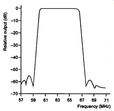
FIG 14 SAW band-pass filter for TV IF
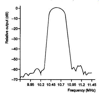
FIG 15 SAW band-pass filter for 10.7 MH FM IF stages
===
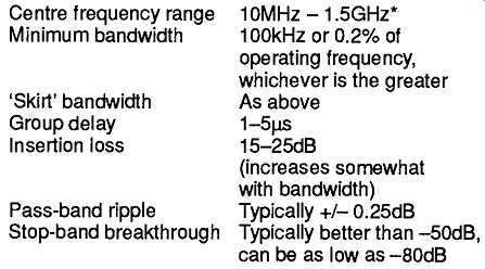
TBL. 2
Center frequency range--Minimum bandwidth
'Skirt* bandwidth--Group delay--Insertion loss---Pass-band ripple--Stop-band breakthrough
10MHz-1.5GHz* 100kHz or 0.2% of operating frequency, whichever is the greater As above 1-5|is 15-25dB (increases somewhat with bandwidth)
Typically +/- 0.25dB Typically better than -50dB, can be as low as -80dB
-----
* The upper frequency limit is imposed, largely, by the shortcomings of the photo-lithographic techniques used to produce the conductor pattern.
===
Higher quality devices may employ similar strips, made from mono-crystalline lithium niobate (LiNb03), bismuth germanium oxide (Bi12Ge02oX lithium tantalate (LiTa03), or quartz. Of these, lithium niobate is preferred for wide pass-band designs, and quartz for narrow pass-band types. Unlike standard LC filters, it’s possible, in this kind of design, to control both the amplitude and phase of the transmitted signal independently of one another. The type of performance which can be obtained is shown in TBL. 2.
Since the velocity of propagation of such a surface wave is of the order of 3000m/s, the physical dimensions of a component of this type can be quite compact.
Also since 95% of the wave energy is confined within one wavelength of the surface, if the strip is more than a few wavelengths in thickness, the rear face of the resonator strip can be cemented to a rigid substrate to give a mechanically robust and vibration resistant component. To prevent spurious end-reflections, the ends of the strip are normally cut at an angle, and a layer of some acoustically absorbent material is normally applied to the regions outside the expected path of the wave pattern.
Resonant SAW systems:
The other application of SAW techniques is in the production of resonant (R-type) filters, where end reflections are deliberately exploited to assist in the formation of standing wave patterns. Such a component has much in common with a quartz crystal resonator, except that the SAW device has superior HF capabilities, covering the frequency range 100kHz -1.5GHz.
The signal/noise ratio of oscillators based on resonant SAW devices is excellent, with a quoted performance for a 400MHz system as better than -150dB at 10kHz from the resonant frequency. At these frequencies there are no comparable quartz crystal resonators.
However, at lower frequencies the frequency stability of an SAW resonator, using a mono-crystalline quartz substrate, is somewhat inferior to that of a normal quartz crystal frequency standard, with temperature coefficients typically in the range 5-90ppm/°C, over a temperature range of +/-50°C.