AMAZON multi-meters discounts AMAZON oscilloscope discounts
Introduction
Active components operate by transforming energy supplied by a power source into some other desired form. Because of this, the way they operate must always be dependent, to some extent, on the quality and purity of the power supply by which they are energized, although one of the aspects of circuit design can be to minimize, where possible, the influence of the power supply on the behavior of the circuit.
Most electronic circuitry will be designed to be powered by some form of DC supply arrangement, although it’s possible to design some kinds of equipment which will work satisfactorily with a raw AC voltage supply rail, and this may be done where low cost is the major design objective. Of the DC sources, the commonest forms are 'primary' (expendable), or 'secondary' (rechargeable), batteries, AC mains powered DC supplies, and solar cells.
In general, the choice of supply type will depend on the total energy requirement, and whether the equipment needs to be fully portable. Solar cell power supplies are restricted to use in medium to high light level environments, and with systems, such as electronic calculators, which require very little power, though output efficiency improvements in such cells are changing this situation.
Batteries (groups of electro-chemical cells, connected in parallel or series) allow a higher output power, but are either expensive to replace or require recharging at intervals. Their use also carries with it the possibility of damage to the equipment with which they are used through leakage of corrosive electrolytes, though improved battery design has led to 'leak free' systems.
AC (mains) supply line operated power supplies will allow an almost unlimited range of available output powers, but they may be heavy, and they will usually restrict the portability of the equipment. They also lead to the possibility of mains hum intrusion into the electrical output of the circuit, either because of the presence of residues of mains frequency voltage ripple on the DC output rails, or by interaction between the alternating magnetic field associated with the mains transformer in the power supply and the internal electrical circuit connections in the equipment with which it’s used.
Battery power supplies:
Depending on the relative costs and service requirements the choice will lie between primary cells -- those types which are used until their output voltage falls below the minimum satisfactory level, but must then be removed and discarded -- and secondary cells, which can be repeatedly recharged.
Primary cells:
Of the primary cells, the choice is between cost and performance -- in terms of their output power to weight ratio, their constancy of voltage output as a function of time, electrical load, and ambient temperature, their output voltage, and their resistance to leakage of electrolyte. The major contemporary cell types are listed below.
Leclanche:
A wide range of 'voltaic' cells was devised, during the early part of the 19th century, based on the combination of various pairs of metals with some acid or alkaline electrolyte, following Alessandro Volta's discovery in 1799 that zinc and silver metal discs, separated by a layer of moist cloth, would generate an externally measurable electrical potential. Most of these cells, such as those due to Daniell, Grove and Bunsen, remained little more than laboratory curiosities, but the system devised, in 1866, by Georges Leclanche which used an electrode pair of carbon (+ve), and zinc (-ve), in an ammonium chloride electrolyte, proved exceedingly successful, and has, with some improvements, been adopted as the basis for the vast majority of inexpensive 'dry' batteries.
In its simplest form, the construction adopted is as shown in FIG. 1, in which a U-shaped thin-walled tube of zinc, is lined on its inside with blotting paper, and is used to hold either an ammonium chloride or a zinc chloride electrolyte, or a mixture of these, with some liquid absorbent or gelling agent, to reduce the likelihood of leakage. Also contained inside the tube is a cloth bag holding the positive electrode, which consists of a carbon rod, surrounded by a mixture of graphite, to help conductivity, and manganese dioxide, which operates both as a 'depolarizing' agent -- to prevent the evolution of gaseous hydrogen at this electrode -- and as a source of oxygen to activate the cell. The cell is completed by crimping a tin plated brass cap on the top of the central carbon rod electrode, sealing the gap between the rod and the outside tube at the top of the cell with pitch, and wrapping a paper label around the outside of the zinc tube. Such cells are cheap to make, have a storage life of up to a year, require little exotic manufacturing technology, and have an adequate output power to weight ratio.
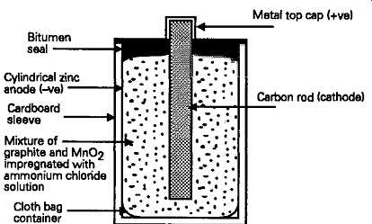
FIG. 1 Simple dry battery (Leclanche cell)
The initial output voltage for a new cell will be in the range 1.55-1.6V, which will gradually fall, during use, to 1.1-1.2V, by which time its service life must be considered to be at an end, since any further discharge beyond this point will cause the output voltage to collapse rapidly to a near-zero level. In more recent cell technology, zinc chloride has largely come to replace the ammonium chloride electrolyte, because it gives a somewhat greater cell capacity: a simple modification which allows the makers to charge a higher price. During the discharge process, the manganese dioxide is reduced to manganese hydroxide, and the metallic zinc electrode is either oxidized to a basic zinc manganate, or combines with the ammonium chloride to form a diammine chloride. If a zinc chloride electrolyte is used, the zinc is mainly converted into zinc oxychloride. In either case the cell becomes discharged when most of the accessible metallic zinc is consumed, or when the bulk of the manganese dioxide is reduced to an unreactive state. Similar processes occur in all of the other cells using a zinc anode, except that those using a potassium hydroxide electrolyte will ultimately convert the metallic zinc into zinc hydroxide or oxide.
The major problem with the simple Leclanche type of cell is that since zinc is consumed during the discharge process, the outer zinc tube will, in due course, become eroded, and will perforate. This is hazardous if the cell is allowed to remain in situ in a discharged condition, since a perforated outer shell will allow the corrosive electrolyte to creep into other parts of the equipment in which it’s used, and this can be exceedingly destructive if not caught in time.
A more modern type of construction, shown in FIG. 2, uses an extruded plastic tube, crimped over tin plated iron top and bottom caps, both to contain the cell, and to form a short-term barrier to the leakage of the electrolyte if the zinc tube should perforate. With improved purity in both the metal used for the zinc tube and the electrolyte chemicals these cells have a much greater storage life -- up to 3-4 years at temperatures up to 20°C. The useful range of working temperatures for this kind of cell is effectively between 5° and 30°C, since with all of these cells the life expectancy and retained capacity are lowered above 30°C, while both the ampere/hour capacity and the maximum output current obtainable from the cell are greatly reduced below 0°C.
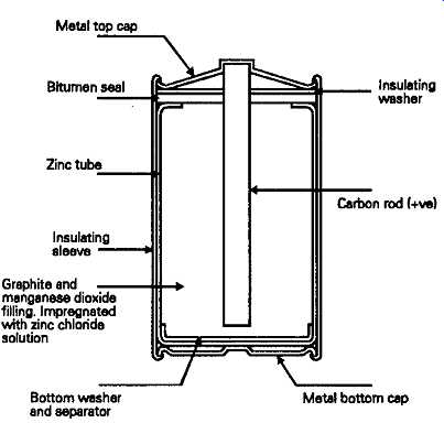
FIG. 2 Improved form of dry cell. The zinc chloride cell
Another common style of this type of battery is the layer cell type, shown in FIG. 3, in which a stack of cells -- usually of four or six -- made in pancake form, and individually contained in a plastics (i.e. an insulating synthetic polymer such as polypropylene or rigid PVC) tube, are mounted within a plastic lined sheet metal jacket, and internally connected to give an output voltage of 6V or 9V. This type of battery was very popular as a source of power for portable radios, but has been rather overtaken by circuit design improvements which allow operation from one or two of the less expensive cylindrical form cells.
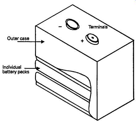
FIG. 3 Layer cell battery
Alkaline manganese cells
While still a zinc/carbon/manganese dioxide system, with a nominal output voltage of 1.55V, this style of cell, shown in cross-section in FIG. 4, gives a substantial step forward in performance in that it gives almost double the storage capacity and shelf life expectancy of the normal zinc/carbon Leclanche cell.
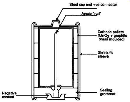
FIG. 4 Alkaline -- manganese cell
To the user, the most conspicuous visual difference is that the cell construction is reversed, with the positive terminal being a protruding dimple formed on the outer metal case, while the negative contact is a cup-shaped disk, insulated from the steel outer case by a plastic sealing washer.
In its construction, the extruded zinc container of the simple Leclanche cell is replaced by a thin sheet steel tube inside which, and in intimate contact with it, is a stack of cylindrical cathode 'pellets', formed under pressure from a mixture of graphite and manganese dioxide. An inner sleeve of porous insulating material separates this from the anode electrode, which is a filling of zinc powder, formed around the zinc current collecting 'nail', and made into a paste with the potassium hydroxide solution electrolyte.
From the point of view of the user, a major advantage, which offsets its greater purchase price when used with expensive electronic equipment, is that the outer steel case is resistant to the electrolyte, and the cell is therefore leak proof under all normal conditions of use. Also, because of the greater efficiency and conductivity of the potassium hydroxide electrolyte, the internal resistance of the cell is lower, which allows greater peak output currents to be drawn for brief periods. However, apart from its greater ampere/hour capacity for a given cell size, the characteristics of the alkaline manganese cell are very similar to that of the Leclanche.
Button cells
Mercuric oxide systems
Both the zinc-carbon systems and the nickel-cadmium rechargeable cells, examined later in this section, tend to be relatively bulky. This is not a particular disadvantage in the case of hand torches, or most of the cassette recorders, cordless telephones or portable radios with which they will normally be used.
However, the advent of miniaturized hearing aid systems, electronic wrist watches, credit card sized pocket calculators, and electronic exposure and shutter control systems in small cameras, created a demand for cells of very much smaller dimensions, and with a much more constant voltage output. Of these, one of the earliest to be exploited commercially was the mercuric oxide-zinc cell, of which the basic system had been invented in 1886 by Aron, and further developed in the 1930s by Samuel Ruben, although Ruben's interest was in the relative constancy of the output voltage of this kind of cell, rather than its capacity for miniaturization.
The method of construction of a contemporary cell of this type is shown in FIG. 5, and consists of a cathode of mercuric oxide, with some graphite to increase its conductivity, compressed into a small flat pellet, pressed into the base of a tin or cadmium plated steel can, and separated from a high purity zinc-mercury amalgam anode by an absorbent pad containing the potassium hydroxide electrolyte. This kind of cell has an output voltage of 1.3-133V, depending on output current, which will remain constant up to the point at which it’s almost completely discharged. This gives the sometimes disconcerting characteristic, for example in electronic wrist watches, that when they do stop, nothing short of replacing the cell will cause them to re-start.
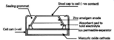
FIG. 5 Mercuric oxide cell Silver oxide-zinc cells
This is very similar in construction and application to the mercury cell, and was also derived from a design originally patented in the mid-1800s (in this case by Clarke) developed in the early years of the 1939-45 war by Andre, as a miniature voltage source for military applications. In this cell, the cathode is a compacted pellet of silver oxide and graphite -- added to increase conductivity. Its output voltage is 1.55V, and, like the mercury button cell it has a very flat output voltage vs. discharge characteristic.
Zinc-air cells
By using atmospheric oxygen, adsorbed onto a catalytic carbon composite layer, as the cathode, more of the internal cell space can be used for the consumable zinc amalgam anode, leading to a greater power capacity for a given volume. The basic construction, shown in FIG. 6, is similar to that of the mercury cell, apart from the fact that the bottom of the cell case is perforated to provide access for air. During storage these perforations are covered with a layer of impermeable tape, which must be removed to activate the cell. However, once the cell has been activated it will continue to discharge slowly, so long as these access holes are uncovered -- a characteristic which makes such cells more suited for applications requiring continuous rather than intermittent use. The output voltage of this type of cell is 1.2-1.4V depending on load current, and it has a discharge voltage characteristic which is similar to that of the mercury cell.
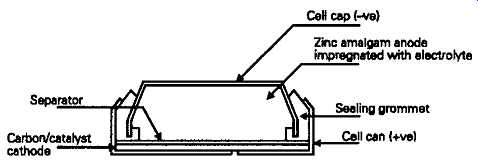
FIG. 6 Zinc-air cell
Lithium cells:
The search for very high power-to-weight ratios in primary cells has led to the exploration of a number of exotic electro-chemical combinations, of which the most successful have been those based on metallic lithium in combination with a wide range of oxide, sulphide or fluoride cathodes. Because lithium will react vigorously with water, it’s necessary to find some non-aqueous solvent for the electrolyte, such as dimethoxyethane.
A commercially available cell (the Ever Ready type 2016 button cell) employs a manganese dioxide cathode and a lithium perchlorate electrolyte to give a 3.2V output voltage, and good storage and discharge voltage characteristics. Similar cells, such as the Crompton 'Eternacell', are available which employ a thionyl chloride electrolyte.
All of these Lithium cells are characterized by a high energy to weight ratio -- up to three times better than the alkaline manganese cell -- a wide operating temperature range (typically -50°C to +60°C), and an exceedingly long storage life, which can be in excess of ten years. This feature is exceedingly useful where a permanent voltage source is required in applications where only a very low output current demand is likely, such as, for example, as a back-up voltage source for 'volatile' computer memory banks, to protect against data loss during a power failure.
It’s essential to avoid reverse (charging) current flow through these cells, an action which can lead to the cell exploding, so the circuit shown in FIG. 7 is normally used in back-up applications to prevent this happening.
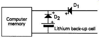
FIG. 7 Lithium cell computer memory back up circuit
Secondary cells:
Those types of cell which can be recharged to restore their initial output voltage and stored energy capacity are known as secondary cells, to distinguish them from the use and throw away types, known as primary cells.
Although it’s possible to recharge standard Leclanche type dry cells, provided that they are not too fully discharged (see Wireless World, August 1981, p. 70, and Feb. 1982 p. 46), the results are not as satisfactory as in the case of cell systems specifically designed for this purpose.
Of the secondary cells which have achieved more general popularity, the major types are the lead-acid, the nickel-iron, or NiFe, and the nickel-cadmium, or NiCad cells. Of these, the lead-acid types are by far the most common, in that they are the standard source of power for starting and lighting motor vehicles.
The specification of secondary cells generally includes both their nominal output voltage and their discharge capacity, in milliampere or ampere hours. In all cells, this capacity is dependent on the effective surface area of the reactive materials on the plates, so means are taken to make this as large as practicable, so far as this is compatible with mechanical robustness and impact resistance. The discharge capacity rating is not usually quoted for primary cells, mainly because it depends on so many factors, such as operating temperature and discharge rate, but, as a general rule, the ampere hour capacity of a D size sealed lead-acid cell would be of the order of 2-2.5Ah, as compared with 4Ah for a NiCad cell, 7Ah for a zinc chloride electrolyte Leclanche type, and 15Ah for an alkaline manganese cell, when discharged intermittently at a 30mA output current.
Lead-acid systems:
In the lead-acid type of cell, the electro-voltaic couple is between lead dioxide (PbO2) and metallic lead, using a dilute sulphuric acid electrolyte, of which the specific gravity, SG, when fully charged = 1.26. This gives an output voltage -- when fully charged -- of about 2.25V/cell, decreasing to about 1.9V/cell when approaching the discharged state.
In a typical open cell system the positive plate electrode consists typically of a hollow lead matrix, of rectangular or honeycomb type cavities filled with lead peroxide, with a negative plate held out of direct electrical contact with the positive one by means of a porous 'separator', having a pocketed or spongy surface. The construction of such a cell is shown, schematically, in FIG. 8. The chemical reaction which occurs during discharge is, theoretically, that the lead dioxide is reduced to metallic lead releasing oxygen, while the lead (negative) electrode is oxidized to lead sulphate, releasing hydrogen. This action consumes part of the sulphuric acid, and releases water by electrolytic recombination, so the specific gravity (SG) of the electrolyte falls during discharge, to a nominal SG when fully discharged, of 1.1. If the cell is allowed to stand for long in a discharged condition, both of the plates may become covered in lead sulphate, and the electrolyte thus further depleted of acid has an increasingly high resistance, which restricts the possible current flow, and makes recharging difficult.
This is described as the battery being 'sulphated'.
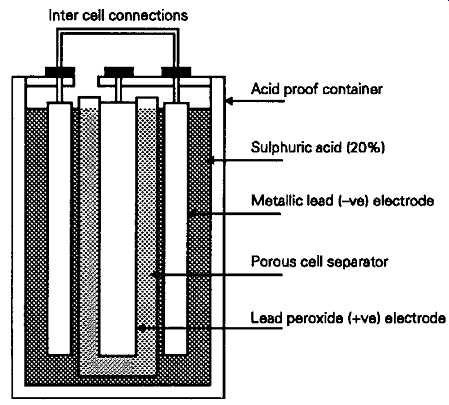
FIG. 8 Basic lead-acid cell
In normal use, the ampere hour capacity of lead acid cells is gradually reduced by the loss of the lead dioxide coating on the positive plate. However, the normal failure mechanism for lead-acid cells is that this lead dioxide, when shed by the positive plate, and then partially reduced to metallic lead, forms a conductive bridge between the plates which permits the battery to discharge even under no-load conditions. In the case of automobile batteries, one might suspect that the design of the battery is chosen to permit, or even encourage, this type of failure mechanism, to prevent the cells from lasting too long! Ideally the level of current used to recharge a lead acid battery should be between C/5 and C/20, where C is the ampere hour rating of the cell. These limits would be referred to, respectively, as 'five hour' or 'twenty hour' charging rates. In emergencies, higher currents can be used, up to 2C, but both high charging and high discharging rates tend to accelerate the loss of lead dioxide from the positive plates. Since both the charge and discharge mechanisms are less than completely efficient, 'outgassing' (the electrolytic evolution of gaseous hydrogen and oxygen) occurs during both the charge and discharge cycles, especially at high current levels. This is unimportant in Open-cell' car battery systems, where provision is made to allow such gases to vent to the atmosphere, with the lost water being replaced as necessary. At high charge/discharge rates the electrolyte may be lost as spray, and simple topping up with distilled water will gradually cause the electrolyte to become increasingly dilute.
In 'sealed' lead-acid cells, the electrolyte will either be held in some absorbent filling material, or as a gel, in order to lessen the possibility of leakage. The type of construction adopted will also be chosen to promote electrolytic recombination. It’s probable also that the manufacturers will recommend a maximum charge/discharge current to help prevent too rapid a rate of evolution of gases.
Lead-acid cells have the advantage of a relatively high output voltage and, when new, a very low internal source resistance, but worries about possible electrolyte leakage have tended to make designers choose NiCad types, whose immunity form this type of problem has been more fully established, even though improved sealed lead-acid systems have now been shown to be exceedingly reliable and trouble-free.
NiFe and NiCad systems
The exploration of systems based on an alkaline hydroxide electrolyte, by Waldemar Jugner in Sweden, and Thomas Edison in the USA, led to the use of both nickel hydroxide/iron and nickel hydroxide/cadmium couples in open-cell batteries, with Edison's NiFe cells being employed first in the early 1920s. These were relatively inexpensive and exceedingly robust electrically -- indeed they had the reputation of being virtually indestructible, but had poor charge efficiency, which led to rapid loss of electrolyte through outgassing, and a relatively low energy density -- only about 25% of the theoretical utilization of active material being practicable at that time. In recent open-cell NiFe types better energy densities of up to 40 50Wh/Kg have been obtained. The output voltage discharge curve of such cells falls from 1.3 to 1.15V at a C/6 discharge rate. A very popular application for such cells was in the 120V 'Milnes' radio HT unit, popular in the 1930-40s as a source of anode voltage in battery operated radio sets. The arrangement of the cells in this unit-individually contained in small glass jars in a wooden case -- was such that they could be switched into parallel groups for recharging from a standard 6V car battery, or back again into series to provide the 120V output.
The use of this type of system in sealed cells was not easily possible, and this factor, together with the improved NiCad energy capacity, led to the greater popularity of the nickel/cadmium types, which can be designed so that there is very little evolution of gas in normal use. The construction of these cells is shown, schematically, in FIG. 9. In this, both the negative (cadmium) and the positive (nickel) plates are formed from a microporous mass of powdered metal, with the nickel electrode being largely oxidized during manufacture to basic nickel oxide (NiOOH). The chemical reaction which occurs during discharge is that this oxide is reduced to the hydroxide (Ni(OH)2), while the released oxygen diffusing through the cell oxidizes the cadmium negative plate to its hydroxide, (Cd(OH)2) --a process which is fully reversible. Although water, from the potassium and lithium hydroxide solution which forms the electrolyte, is involved in this process, it’s not consumed in normal use, so, in sealed cell manufacture only the amount judged to be theoretically necessary is provided.
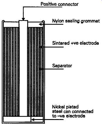
FIG. 9 Cylindrical form Nickel-Cadmium cell
If charging is continued beyond the fully charged condition surplus cadmium on the negative plate is able to convert the oxygen evolved on the nickel plate back to water, only heat being evolved. The warm-up of the cells can be used as an indication that they are fully charged.
The major failure mechanism in NiCad cells is the loss, by electrolysis, of the available water in the system as a result of inadvertent reverse charging -- a process which can happen, all too easily, if current is drawn from a partially discharged battery which contains one cell which has become more completely discharged than the others, but can also occur if the cell is excessively over-charged.
A further mechanism to which more gently used NiCad cells seem particularly prone is the growth of fine threads of conducting metallic cadmium -- known as 'dendrites' because of their tree-like structure --through the porous separator between the plates, which not only causes the cell to discharge, but may also prevent its being charged again because of the internal shortcircuit which is present.
These failure mechanisms were examined in detail by Cooper (Wireless World, May 1985, pp. 61-63, June 1985 pp. 60-63, and July 1985, pp. 32-36.), and the means of restoring internally short-circuited cells to working order, by subjecting them to bursts of charging current large enough to fuse the cadmium dendrites is examined by Johnson (Wireless World, February 1977, pp. 47-48). On the credit side, such cells are relatively light and mechanically robust, largely trouble free in normal use, and are capable of very high output currents over brief periods, if needed.
Indeed, a very successful range of portable soldering irons has been marketed, powered by NiCad cells housed in the handle, which supply a current to the low resistance heater element which is high enough to bring the bit up to operating temperature within a few seconds.
Various charging systems have been suggested for NiCad cells, but the most straightforward is to re charge them separately at a fixed voltage of 1.42V/cell, when damage due to overcharging is not possible. Where fixed voltage charging is not feasible, current charging rates in the range C/5 to C/10 are usually recommended -- preferably combined with a cell temperature rise cut-out mechanism.
The output voltage discharge curve is very flat, falling from 1.22V to 1.19V at the threshold of discharge, at a discharge current of C/5. Immunity to self discharge is reasonably good in modem cell designs, though less satisfactory in sintered plate systems.
Other rechargeable cells have been devised, based on, among other possibilities silver-zinc (1.5V), silver-cadmium (1.1V), and Nickel-Zinc (1.8V) types, but these remain relative rarities.
I have illustrated in FIG. 10 the relative output voltage discharge curves for the more common primary and secondary cell types, scaled to represent the performance which would be given by cells having an equivalent physical size, and discharged at the same C/JC current flow.
I would like to express my gratitude to the Ever Ready and Duracell battery companies for their generous provision of technical information on this subject.
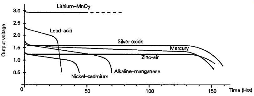
FIG. 10 Voltage output and energy capacity for common cell types
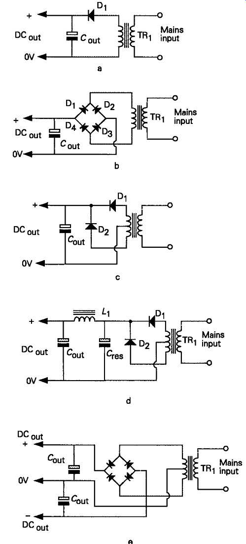
FIG. 11 Simple transformer-rectifier power supplies
Mains operated power supplies
Simple transformer-rectifier systems:
The need to provide a stable, reasonably noise and ripple free DC output from a 50 or 60Hz AC power supply line is capable of being met by a wide range of circuit layouts, but, in general, the designer must first decide how good a quality of output DC is needed by the system to be powered, and to what extent a more expensive or complex power supply layout would be justified by circumstances.
In its simplest form, a DC output can be provided by any of the transformer/rectifier/capacitor layouts shown in FIG. 11. A point which must always be borne in mind, in any rectifier/reservoir capacitor layout, is that, on light load, the output voltage will be 1.414 times the RMS AC output voltage provided by the transformer secondary winding. This means that the energy output for which the transformer is rated, in volt-amperes, usually abbreviated to VA, must be down rated by a factor of, at least, 1.414 to allow for the fact that the output current from the power supply is being drawn, effectively, at a higher voltage than the secondary RMS output value. This means that, in the case of the simple circuit layout of FIG. 11a, if the secondary winding is rated at, say, 1A, the maxi mum output current which can be drawn from the supply will be 0.707A, even though, under load, the resistive and core losses in the transformer, and the inevitable forward (conducting), voltage drop across the rectifier diode, will mean that the voltage actually developed across the reservoir capacitor, C1 will actually be a good bit less than 1.414 Vout. Also, in practice, the maximum output current will be reduced even further because the current drawn from the secondary winding of the transformer will take the form of short duration high-current pulses, as shown in FIG. 12. It must be remembered that the core and winding resistance losses are proportional to T2 rather than I, so the high output current pulses drawn from the secondary winding will cause a disproportionately high transformer dissipation.
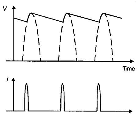
FIG. 12 Voltage and current waveforms --half wave rectification.
The allowance which must be made for this effect cannot be precisely specified because it depends on both the transformer core characteristics and the size of the reservoir capacitor employed -- the larger the capacitance of this the shorter in duration and the larger in magnitude the repetitive charging current pulses will be. A working rule of thumb is that the DC output current (f_dc) should not exceed 0.65 /ac. This leads to the need for a design compromise, in that, if the DC output is to be drawn directly from the reservoir capacitor, as is increasingly the case with modern transistor and IC power supplies, the desire to keep the output ripple level low would urge the use of a large value reservoir capacitor, but, because this will cause the current drawn from the mains transformer secondary to be reduced to progressively shorter reservoir capacitor charging pulses, this worsens the transformer efficiency and heat dissipation. However, the inevitable secondary winding resistance, coupled with core saturation effects, means that, in practice, there is an upper limit of reservoir capacitor size, beyond which no further benefit will be obtained.
The 'choke-input' filter system shown in FIG. 13 makes much better use of the potential power output from the transformer, but the DC output voltage developed across the reservoir capacitor, C1 will al ways be somewhat less than the transformer RMS secondary voltage. Also, because of the need for a gapped core 'swinging' choke -- a somewhat rare type of component, which will add to the bulk and component cost of the circuit -- this type of power supply system is rarely found in low to medium output power designs.
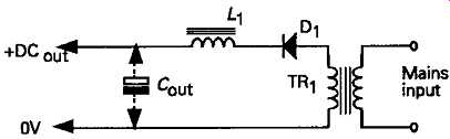
FIG. 13 Choke-input filter system.
Where just a single line or a pair of +/- supply lines are needed, the most common types of circuit are those shown in FIGs 11b, c, d and e, where 'full-wave' rectification is employed to double the frequency of the charging pulses fed to the reservoir capacitor, and nearly halve the magnitude of the residual sawtooth supply line ripple. A comparison which is illustrated in FIG. 14.
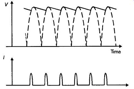
FIG. 14 Voltage and current waveforms. Full wave rectification
Even with full-wave rectification, and a large value reservoir capacitor, there will always be a significant amount of (100/120Hz) ripple on such a DC supply output, and it’s inevitable that the mean output voltage will fall and the ripple content will worsen as the output current demand is increased. However, such simple systems are very widely used and, with care in the design of the circuitry to be used with them, are often quite adequate for their purpose.
In valve operated electronic systems, where relatively high DC supply line voltages were used, and the DC current demand was therefore proportionately lower, it was conventional practice to insert a 'smoothing choke' (L1), between the reservoir capacitor (C1), and the output 'smoothing capacitor' (C2), as shown in FIG. lid. This converts L1/C2 into a -12dB/octave LC type low-pass filter and substantially reduces the amount of residual sawtooth HT ripple present in the output circuit: a ripple voltage which is caused by the way in which the rectifier/reservoir capacitor charging mechanism acts.
However, with high current, low voltage, power supplies the additional DC resistance introduced into the output path by a series choke of adequate inductance to be useful would be undesirable, and the use of such series connected chokes has become a rarity; particularly since output voltage smoothing can be provided in a much more compact and economical way, if needed, by the use of a voltage regulator circuit.
Voltage regulator systems:
It’s often necessary to supply the operating circuitry with a substantially constant, and ripple free, DC voltage -- a requirement which cannot be met by any simple mains transformer/rectifier layout. Such improved supply stability can be provided by the use of some kind of stabilizer or regulator circuit, and these can be divided into 'shunt' and 'series' systems.