AMAZON multi-meters discounts AMAZON oscilloscope discounts
The importance of measurements, and the need for testing:
I suppose it’s true of any field of human endeavor that nothing goes right all the time, and that much care is needed even to make sure that things go right most of the time. Certainly, my own experience in the practice of electronics, and my observation, over the years, of the various problems which have been en countered by my colleagues in this field, has taught me to recognize the potential fallibility both of human beings and of the materials they choose to employ. In particular, however skilful the designer may think he has been in his initial concept, and however thorough he feels he has been in his calculations, there is always a possibility that he may have overlooked some relevant aspect of the system which he has designed. It’s also possible that he may have been aware of, but dismissed as unimportant, some factor which was more significant than he had realized.
Similarly, when a prototype is built to a design which is, in itself, entirely satisfactory, there is always some chance that a constructional fault or a component defect will cause a circuit malfunction. In most cases the existence of a problem will be immediately obvious, and investigations will be made to find its cause and put it right. However, if the fault, due either to design or to component error, is not a particularly conspicuous one, it may remain unseen, resulting in an unexpectedly poor performance of the system. The only really satisfactory way of avoiding the problem of unseen malfunctions is to take very little for granted, and always to make at least a few appropriate measurements of the static and dynamic characteristics of the circuitry. In this task the better the test equipment available, and the more skilled the engineer in its use, the easier it becomes to check whether things are working as they should do -- and, if they aren't, why not.
By static tests, I mean those which relate, in the main, to measurements made on the components in use, such as their resistance, capacitance or inductance (and if there are any doubts about component characteristics, it’s usually much easier to check these before they are installed in the circuit), or to the quiescent conditions which exist in the equipment under test, such as measurements of its DC voltage and current levels, and, perhaps, its operating temperatures.
Dynamic tests are those measurements which are made on the system when it’s in operation -- usually with a known input test signal -- and include output voltage or current swing, frequency and transient response, waveform distortion, voltage or current gain, input or output impedance as a function of frequency, signal to noise level, and, in the case of signal sources, output frequency and frequency stability.
Although I am sure that most 'proper' design engineers would frown on such a suggestion, the use of appropriate test equipment can save a lot of time in calculation, in showing which system works the best, if there is a choice between several, and also, at the prototype stage, in checking that the optimum component values have been chosen for the system. One must always remember, however, that component values may not always be what their markings indicate, and also that components will vary anyway, so the skilled engineer should always seek to design for a median value, to make sure that the system will still work well with component characteristics which depart some what from the ideal value. So, don't 'tweak' a system for perfection, if that perfection then rests on the edge of a performance precipice, or you may find that while the prototype works excellently, all its successors are duds.
Static testing (voltage, current and resistance measurement)
Voltmeters:
Like some of the other test instruments, these come in two basic kinds, 'analogue' and 'digital', and there is also a division between 'direct reading' and 'electronic' instruments -- digital meters will, obviously, be electronic in their nature. Each of these types have their own advantages and snags.
An ideal voltmeter should present an infinitely high shunt resistance when connected across the circuit under test. Similarly, an ideal current meter should cause a zero voltage drop when it’s inserted in a circuit to measure direct current flow.
Electronic measurement instruments can come much closer to this ideal than any direct reading meter, but require an external power source -- usually a battery, which leads to the disadvantage that it will run down if the meter is inadvertently left switched on --and may suffer from zero or calibration drift with time or changes in temperature.
Digital instruments can give a much greater degree of precision in reading (usually limited to +/-1 in the least significant digit), particularly in measurements of circuit resistance, and are particularly useful in determining the differential potential existing between non-zero points, such as across the load resistor (points 'x' and 'y') of the simple amplifier circuit shown in FIG. 1. However, they don’t usually approach the ideal zero voltage drop condition in current measurement applications as closely as, for example, an electronic analogue meter, and they are virtually use less for measurements of changing voltage or current levels, which makes them very awkward to use as a peak or a null detector during circuit adjustments.
There are, indeed, some digital voltmeters (DVMs) which have a ten or fifteen segment 'bar-graph' display, in addition to the digital read-out, but these offer nowhere near the delicacy of adjustment possible with even a cheap analogue meter.
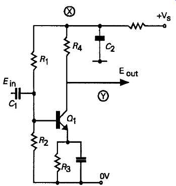
FIG. 1
Most direct reading analogue displays are based on the use of a 'moving coil' indicating instrument, some times called a d’arsonval movement, after its inventor. The construction of these is shown, schematically, in FIG. 2. In this, a coil of wire, wound on a thin rectangular former, is suspended in the gap between a pair of magnetic pole-pieces, and pivoted so that it’s free to swing about its axis. A pointer is attached to this movable coil, and the whole movement is caused to return to some predetermined zero position by means of a pair of spiral wound springs. These are mounted in opposition, so that very little torque is required to cause the movement to swing about its axis. The displacement of the meter movement away from its zero position is due to the interaction of the magnetic field due to the permanent magnet and that due to passage of current through the coil to which the external meter circuit is connected. The resulting movement of the coil is related to the strength of the permanent magnet and the smallness of the air gap in the magnetic circuit. This is reduced by inserting a soft iron collar into the gap between the permanent magnet poles, and the profile of this can be adjusted, if required, to improve the linearity of the display. Ideally the instrument should be both sensitive and robust.
Unfortunately, these requirements are in conflict, in that high sensitivity of indication implies a light coil wound with fine wire, suspended by delicate springs on very low friction bearings in a narrow magnetic gap, while robustness demands the opposite. The skill of the instrument manufacturer lies in resolving these conflicting requirements, especially if, as is common, the movement is to be used in a multi-range test instrument which may have a rough life. A fairly common safety precaution with high sensitivity moving coil (m/c) meters is to incorporate a 'cut-out' mechanism which will interrupt the electrical circuit to the meter movement if the pointer travels beyond its full-scale reading, or if the acceleration of the pointer exceeds some predetermined value.
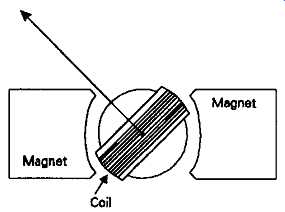
FIG. 2 The d’arsonval m/c meter movement
If a moving coil instrument is to be used solely as a DC voltage indicator, a high resistance, multiple turn coil can be used, the upper limit to the number of turns, and the consequent coil resistance, being set by the lowest full-scale deflection (FSD) voltage likely to be required from the movement. If, on the other hand, it’s to be used solely as a direct current indicator, a low resistance coil would be preferred, with the lower limit to the number of turns being set by the minimum current required for a FSD display.
Typical commercial instruments are offered with FSD current ratings of 25, 50, 100, 250, 500µF, and 1mA, with display scale lengths of 3.8-15cm. The accuracy of indication is generally greater in those movements with longer scale lengths, and ranges, typically, from +/-2.5% to +/-0.25%.
To use a current indicating meter as a voltmeter, an additional resistance, called a 'multiplier', is usually connected in series with the coil, as shown in FIG. 3a. The value of this resistance is determined by the relationship:
RM =Rt-Rc
…where Re is the total meter coil resistance, RM is the value of resistance required for the multiplier, and Rt is the total circuit resistance needed to satisfy the condition that:
V/I=Rt
…where I is the meter movement FSD current and V is the required FSD voltage display, in amps and volts respectively.
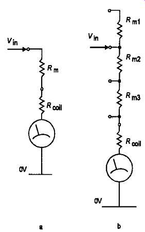
FIG. 3 Connection of multipliers in a moving coil voltmeter circuit
It’s apparent that the meter can be made to display as high a FSD voltage value as required by this means, provided that the multiplier resistors are able to sup port the voltage present between their ends. In normal practice, high voltage multipliers are arranged by connecting a number of lower value resistors in series, and if the value of the multiplier resistors can be altered by switching, as shown in FIG. 3b, a multiple range indicating instrument can be made.
Current meters
In principle, the FSD current reading given by a meter can also be changed by connecting other resistors, known as shunts, in parallel with the coil, as shown in FIG. 4a. However, this method of operation tends to demand very low value resistors to give correct operation at high FSD current ratings. As a solution to this difficulty, the 'current multiplier' circuit layout shown in FIG. 4b is normally used -- particularly in multi-range test meters -- because this effectively adds a voltage multiplier to the meter circuit, at higher FSD current taps, and allows the shunt resistors to have somewhat higher values, which arc easier to make.
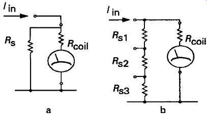
FIG. 4 Use of moving coil movement as current meter circuit.
Resistance meters
In essence, a resistance meter (ohmmeter), is simply a current meter to which a voltage source, B1, can be connected by way of the 'unknown' resistor, as shown in FIG. 5a. An adjustable resistor, RV1, is also connected in the circuit to allow the full-scale reading to be correctly set for a zero resistance value. The higher the voltage provided by B1 and the lower the FSD current of the meter, the higher the value of the FIG. 5 Use of moving coil meter as a resistance measurement circuit unknown resistor for which a measurement can be made.
For measurements on lower values of resistor, a simple design approach is to shunt the m/c movement so that it has a greater FSD current rating. Another method is to use the circuit shown in FIG. 5b, in which the unknown resistor is connected in the position of a current shunt. This layout has the advantage that the resistance reading is in the correct direction --i.e. with the zero resistance value at the LH end of the indicator scale.
Meter sensitivity
As mentioned above, there is a conflict between the requirements of ruggedness and sensitivity in any simple direct-reading analogue instrument, simply be cause the amount of current which the instrument needs to draw, in order to generate the magnetic field needed to displace the pointer from its rest position, increases as the solidity of the coil and the strength of the springs is made greater. Recognizing this fact, the sensitivity of a moving coil voltmeter is normally expressed as Ohms per volt'. A low-sensitivity, and robust, instrument might well be specified as 1000 ohms/volt, which would imply that it was based on a basic 1mA FSD current meter. A10 volt range on such a meter would imply a total meter plus multiplier resistance of 10,000 ohms, similarly a 100V range would imply a total meter resistance of 100,000 ohms.
If a voltage measurement was made using such an instrument it would be inaccurate to the extent that the current drawn by the instrument, which would be in the range 0-1mA, would reduce the potential at the point of measurement. If the circuit being measured was a low resistance one, the error could be tolerable, but in a high resistance circuit the error could be quite large, and, perhaps, in a valve or FET circuit, with high circuit resistances, the change in DC potential which occurred, when the voltmeter was connected, might be so great that the circuit would no longer work correctly.
A more sensitive, and probably more delicate, instrument could well be rated as 20,000 ohms/volt, which would indicate that the fundamental meter movement was of a 50µF FSD type. With such a meter, a 10 volt range would present a meter circuit resistance of 200,000 ohms.
There are, of course, always snags and a basic 50µF movement would probably require 300mV to be applied to the coil to produce a full-scale deflection. This would determine the minimum voltage drop which would be produced by the meter in use as a current meter, which should, ideally be zero.
Moving iron meters
These are not very often found in small power electrical and electronic circuitry, but arc still moderately common in higher power systems. These consist basically of a fixed coil through which the passage of current generates a magnetic field which attracts a pivoted magnetic 'tongue' away from some spring loaded rest position. These movements don’t offer very high sensitivity, but are robust and can be made quite linear. They can offer comparable accuracy to m/c designs.
Electrostatic movements
These instruments make use of the electrostatic attraction which exists between two oppositely charged plates -- or between a charged plate and an earthed plate -- to produce a deflection in a spring-loaded pivoted movement similar to that of a moving coil meter. However, in this case, instead of a coil twisting in a magnetic field, the pivot carries one or two suit ably shaped plates which are arranged so that they may be drawn, by electrostatic attraction, into the gap be tween an oppositely charged pair. The layout used is shown, schematically, in FIG. 6.
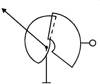
FIG. 6 Schematic arrangement of an electrostatic meter movement.
Meters of this type have the advantage that they draw a negligible amount of current from the circuit under test, and since they are insensitive to polarity they can be used to measure AC as well as DC. However, they are not very robust, and they are seldom available for FSD voltages of less than 500V (2.5kV 10kV arc more common ratings), and their meter scale is very non-linear, being very cramped at the low voltage end.
Electronic analog meters
A whole new range of test instruments can be made by combining an electronic amplifier with a moving coil milliammeter movement, and these can combine high sensitivity with robustness and freedom from damage through input overload. In the earliest of these instruments, a typical circuit design made use of a balanced long-tailed pair, of the kind shown in FIG. 7 for an arrangement based on discrete transistors. In this type of layout, the display meter is connected between the drains of the two J-FETs, Q1 and Q2, and the voltmeter input is connected, via a suitable voltage multiplier chain, to the base of Q1. A preset trimmer potentiometer connected between Q1 and Q2 sources allows a 'set zero' adjustment.
With contemporary components, a similar result could be achieved, at a much lower level of static battery drain, by the use of an opamp connected as a unity gain voltage-follower, as shown in FIG. 8a. In this circuit, the minimum FSD voltage will be that which would be required to drive the m/c movement to full scale, on its own, but with an input resistance which could be almost as high as one wished, particularly if one used an FET-input opamp type, such as a TL071 or an LF351.
Greater sensitivity can be obtained by connecting the opamp as a DC amplifier, as shown in FIG. 8b. In both cases, a meter zero adjustment can be arranged, if needed, by the use of the opamp 'offset adjust connections' (usually pins 1 and 5 in the 8 lead pin-out configuration) provided for this purpose.
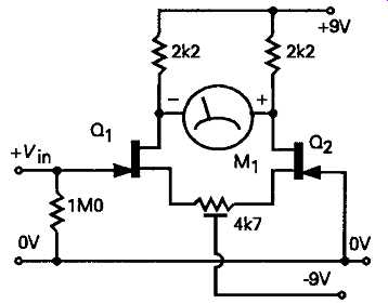
FIG. 7 Simple electronic voltmeter
A somewhat more elegant, and certainly more versatile, circuit layout is shown in FIG. 9, in which the m/c meter movement is connected in the opamp negative feedback path. In this case, the internal resistance of the m/c movement is almost irrelevant, pro vided that its FSD current demand is less than the maximum permitted output current of the opamp., and the meter FSD is determined solely by the chosen setting of the preset potentiometer RV1. This situation arises in this type of circuit layout because the feed back loop will operate so that the potential difference between the + and -- (non-inverting, and inverting) inputs will be the opamp output voltage (the voltage required to drive the meter to its appropriate scale deflection) divided by the opamp. open-loop gain.
For example, if the opamp has a DC gain of 100,000, and the meter requires 300mV for FSD, the differential input voltage required between the +in and -in connections will be 300/100,000 mV, or 3µF, which is negligibly small.
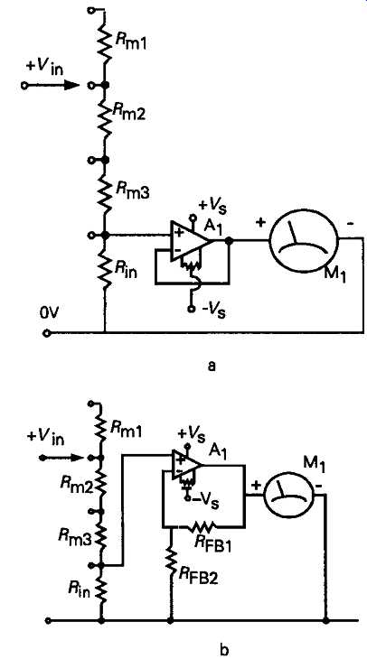
FIG. 8 Improved electronic voltmeter circuits
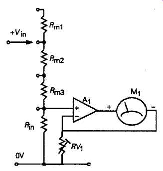
FIG. 9 Unity voltage gain
In addition to the ability of such a circuit to operate as an exceedingly high input impedance voltmeter, this kind of layout would also allow the construction of a test instrument which had an exceedingly low voltage drop when used as a current meter. For example, the circuit would require an input voltage differential of only 1mV for a meter FSD, if one employed a 500mA m/c display movement and RV1 was set to 20 ohms.
This kind of circuit arrangement would also allow the construction of a very high sensitivity ohmmeter, when used in either of the circuit layouts shown in FIG. 5.
Digital meters
In general digital instruments supplement rather than supplant their analogue predecessors, since both systems have advantages and snags, as noted above. A variety of techniques are used to derive a numerical read-out proportional to the input DC voltage, of which the two most common are the 'double ramp' system, and the 'successive approximation' method.
A typical digital voltmeter circuit layout using the double ramp system is shown, in schematic form, in FIG. 10. In this, the input (analog form) signal is amplified, as required, by an input buffer stage, and used to generate an output current which is directly proportional to the input voltage. This current is then caused to charge a high quality low leakage fixed capacitor for a precisely controlled period of time. At the end of this time, an electronic switch is actuated which causes the ramp output voltage to fall linearly towards zero, through a constant current load circuit.
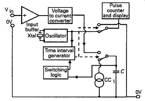
FIG. 10 Schematic layout of digital voltmeter
This switch also resets the pulse counter so that it will display the number of clock pulses which occur during this downward portion of the voltage ramp, in the time between the ramp voltage starting its downward slope and reaching the zero level once more. A single cycle of operation is shown in FIG. 11.
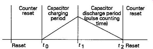
FIG. 11 Operating cycle of double ramp digital voltmeter
Because such digital signal conversion systems usually have a fixed full-scale input voltage range, such as 0.1999V or 1.999V, and the use of input voltage gain stages will increase the risk of zero drift, digital current meters usually have a greater insertion voltage drop, sometimes called the voltage burden, than electronic analogue instruments. However, with this proviso, it’s just as simple to construct a multi range digital volt/amp/ohm meter using a digital display meter as it’s to do so with an analogue one, using the types of circuit arrangement shown above for analogue meters. The AC bandwidth of inexpensive digital multimeters (DMMs), is usually limited to a few kHz by the characteristics of the coupling trans former/rectifier circuit used to derive a DC output voltage from the AC input signal.
The successive approximation technique uses the internal electronic 'clock' to generate a binary coded sequence of decreasing magnitude voltage steps, as shown in FIG. 12. At the end of each step, the output from a voltage comparator is used to sense whether the sum of the 'step' voltages is greater or less than the input voltage, and then either to reject (logic 0), or to accept (logic 1), the last binary encoded voltage step from the binary staircase sequence. This provides, directly, a digitally encoded transform of the input voltage level at the instant of sampling.
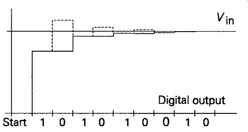
FIG. 12 Operation of successive approximation type of digital voltmeter
Inductance and capacitance measurement
Various techniques are used to make these types of measurement, depending largely upon the relative importance of convenience or precision. Of the various systems which have been proposed or used, the most common, in the past, was one or other of the 'bridge' arrangements shown in FIG. 13, in which the resistance or impedance of one or more of the arms of the bridge would be adjusted to give a 'null' reading on some adequately sensitive indicator mechanism. If the adjustments of the reference arms are precisely calibrated, bridge measurement systems can give high accuracy, but achieving a null reading may require the sequential adjustment of several controls, which is usually time consuming.
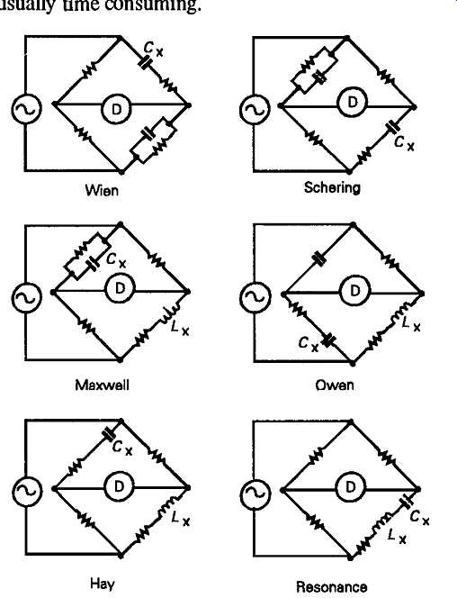
FIG. 13 Some of the common bridge circuits used for inductance and capacitance
measurement --- Wien Schering; Maxwell Owen; Hay Resonance.
Alternatively, the value of the component under test can be measured by connecting it in a circuit whose performance is determined by the inductive or capacitative impedance of the unknown component, perhaps as part of the frequency determining network in an LC or RC oscillator, from which the value of the L or C can be discovered by noting the resultant resonant frequency of the system.
However, for a simple indicating meter, the most straightforward approach is just to use the kind of layout shown in FIG. 5a, but using an AC current measurement circuit, with a source of AC voltage in place of Bl. One can then make use of the fact that, for any input frequency, there will be a precise relationship between alternating current flow and the value of the capacitor or inductor, in Farads or Henries. Appropriate AC current meters are shown in the section covering dynamic measurements.
Measurement of Q:
A particular type of measurement which is of interest where inductors are intended for use in resonant circuit applications, more particularly at high frequencies, is that of the circuit magnification factor, or Q. A variety of techniques have been proposed for this purpose, but many of these are variations of the simple layout shown in FIG. 14, in which the magnitude of the AC voltage developed across a tuned circuit, with a standard value, high quality capacitor, in series with the unknown inductor, is determined when the system is forced into resonance by an input signal from a constant output voltage AC signal generator.
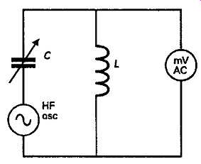
FIG. 14 Simple Q meter
The measurement of LC resonant frequency will also allow the values of the capacitor or inductor to be determined, by calculation, from the relationships ...
... where f_r is the frequency of resonance, and L and C are the values of capacitance and inductance of the components under test, provided that the signal generator output frequency, and either the value L or C is known.
Chopper type DC amplifier systems
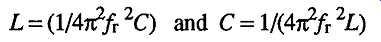
Dynamic testing Because of the difficulties associated with voltage drift in electronic amplifiers, due to thermal effects and component ageing, the measurement of very low voltage levels presents particular difficulties. A commonly used method for avoiding or minimizing this problem is the use of a chopper system of the kind shown, schematically, in FIG. 15. In this circuit, an input switch, S1, is used to connect the input of a gain stabilized AC amplifier alternately to the input DC signal voltage and to the signal OV line. If the input switch is rapidly reciprocated between these two input points, the incoming DC potential will be converted, at the input to the amplifier, into an equivalent alternating rectangular waveform, and this can then be amplified. If the amplified AC output signal is then rectified, it will provide a DC output which is directly proportional to the input DC voltage, but unaffected by any drift in the amplifier DC levels. In early systems, the chopper mechanism was commonly used to operate switches working in synchronism at both the input and the output of the amplifier, in order to provide the necessary output AC to DC conversion, but, with contemporary equipment, electronic input switching systems and AC/DC conversion techniques -- see below -- are more commonly employed.
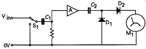
FIG. 15 Simple chopper-type DC amplifier.
The simple system shown in FIG. 15 would only be able to operate with steady state, or only slowly varying, input signals -- depending on chopper speed.
This has encouraged the development of chopper stabilized systems, in which a conventional opamp. is used as the amplifier, but with a 'nulling amplifier' used to monitor and cancel the main amplifier DC drift. Because of the great value of such chopper stabilized amplifiers for low level DC signals, complete circuits of this kind are now available as IC packages, such as the LCT1052, the ICL7650 and the ICL7652 devices. These offer effective input DC drift levels as low as 100nV/_/month.
Dynamic testing
AC voltage and current meters
Direct reading instruments:
The simple d’arsonval type moving coil current meter can be used to indicate the magnitude of an applied AC voltage or current by rectifying the input voltage waveform, using one or other of the rectifier circuit arrangements shown in FIG. 16, but all of these arrangements will suffer, to some extent, from the fact that all solid-state rectifiers have the less than ideal kind of conduction characteristics shown in FIG. 17. The principal problem which results from this type of forward/reverse conduction characteristic are that a finite forward voltage must be applied before the rectifier will conduct at all, and that there will also be some reverse conduction.
FIG. 16 Meter rectifier circuits
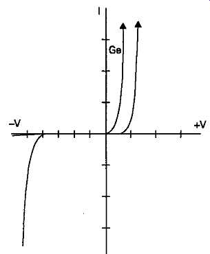
FIG. 17
Those types of rectifier, such as the silicon junction diode, which have low reverse leakage currents, at voltages below their reverse breakdown potential, require a forward potential of 0.55-0.6 V before they will conduct at all, while those rectifying diode systems, such as germanium P-N junction diodes, or cop per/copper oxide rectifiers, which have relatively low forward threshold potentials, suffer more from reverse leakage. This means that any simple meter/rectifier circuit will tend to be rather nonlinear in its response to low voltage inputs: a problem which can be minimized by including a resistor in series with the meter movement, of a value which will swamp the variation in the rectifier resistance with voltage in its forward (conducting) direction.
Waveform sensitivity:
A further problem with any alternating voltage indicating instrument is that its indication will be influenced by the waveform of the input signal -- as shown in FIG. 18 -- a circumstance which will be of little importance with a symmetrical sinusoidal input waveform, but will influence the reading quite a lot if the input signal is non-sinusoidal: a factor which must be borne in mind when making measurements.
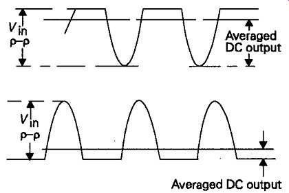
FIG. 18 Influence of input waveform on average DC output voltage
A simple half-wave rectifier circuit such as that shown in FIG. 16a, will, with a sinusoidal input voltage waveform, give an output which is approximately half the RMS value. If the meter is calibrated to take this factor into account, it would give an erroneous reading -- either too high or too low -- if the input voltage waveform was non-symmetrical. The particular circuit illustrated would also suffer from the problem that any DC component, associated with the AC voltage to be measured, would also affect the meter reading, as would also be the case in the full wave rectifier circuits of FIG. 16e, and 16f.
This problem can be avoided by using an input DC-blocking capacitor, as shown in FIG. 16b and 16c, but with the penalty that the meter would lose sensitivity at lower measurement frequencies, unless C1 was made adequately large. Since an alternating input voltage would be applied to the rectifier circuit, a polar (i.e. electrolytic) capacitor type would be unsuitable, and large value non-polar (i.e. polyester or polycarbonate film type) capacitors are bulky.
The current transformer input arrangement shown in FIG. 16d provides a better solution to this problem, in that, in addition to isolating the meter/rectifier circuit from any incoming DC potentials, if it’s connected as a voltage step-up component, it will allow the voltage present across the meter/rectifier circuit to be increased, thereby reducing the importance of rectifier nonlinearity. Such an input transformer will, of course, also impose some limits on the bandwidth over which the meter will give an accurate reading.
Full-wave rectifier systems such as the voltage doubler layout of FIG. 16c, and the bridge circuits of FIG. 16e, and 16f, tend to be less affected by input waveform asymmetry, because they tend to average the readings from the two halves of the wave form. However, while a sinusoidal input will give a meter reading which approximates to a true RMS value (0.707Vin) in the case of a sinusoidal signal; a rectangular waveform will give a peak value reading, and both triangular and sawtooth waveforms will give readings which approximate to half of the peak value.
All of the circuits shown in FIG. 16 can be made to give an approximate peak voltage indication by putting a capacitor, C2, across the meter, as shown in FIG. 16a.
Because of the need to insert a swamp resistor in series with the meter movement, to lessen the nonlinearity of the scale reading due to the rectifier characteristics, it’s common practice in commercial instruments to use the layout shown in FIG. 16f, where a pair of swamp resistors are used in place of the other half of the rectifier bridge, either as shown or, more commonly, in combination with a DC-blocking input transformer, as shown in FIG. 16g.