AMAZON multi-meters discounts AMAZON oscilloscope discounts
.
.DC voltage tests are usually the first step in troubleshooting, since the dc voltages of a device usually provide the basis for operation. The fact that they are one of the easiest tests adds to this reasoning. The remainder of this section focuses on the wide range of power supplies and their circuits.
DC voltage measurements
DC voltage is measured with a dc voltmeter. This sounds a little obvious, but there are several different types of voltmeters, and some circuits need the right type if test readings are to match a standard.
Three basic types of voltmeters are in wide use today. The first is the analog voltmeter, which uses a swinging needle over a calibrated scale (d’Arsonval movement). These meters have an adjustable resistance in series with the leads to allow proper range selection. The second major type is the vacuum-tube volt meter (VTVM), or its transistorized counterpart, which uses an amplifier to drive the meter movement. The third major type is a relatively recent development. The digital voltmeter uses an analog-to-digital (A/D) converter to directly display the measured value in numeric form on an LED or LCD read-out panel. No mechanical meter movement is used.
In the analog type, the meter movement and its series resistance are hooked directly across the circuit under test. For measurements with a VTVM, a very large voltage-divider resistor is hooked across the circuit; the meter is driven by a dc amplifier whose input is “tapped down” on this voltage divider to obtain the desired range. Digital voltmeters are generally used in the same manner as mechanical VOMs. That is, the test leads are connected directly across the circuit or component to be tested. Each type of meter has its own uses, advantages, and disadvantages.
When it comes to using voltmeters, the most importance difference between the VOM (analog) type and the VTVM (tube) type is in their input impedance, or resistance. The input impedance of the meter sometimes can affect the voltage reading you get. The 1,000 per-volt meter—a typical analog voltmeter— must offer a total resistance of 1,000 for every volt of the full- scale range you want to be able to read. Such a meter, set to a 10 V (full-scale) range, would have a total resistance of only 10,000 on a 200 V range, it would have a resistance of 200,000 ohm. the 20,000 ohms per-volt meter—another analog voltmeter—is much more sensitive. With this meter, the 200 V range has a total resistance of 4 million ohm (4 M-ohm).
The unofficial standard for VOMs is 20,000 ohm per volt. Many modern VOMs have input resistance ratings of 50,000 ohm per volt, or even 100,000 ohm per volt. The earlier 1,000 per volt VOMs are rarely used, except in very noncritical applications.
Problems with circuit breakers
A circuit breaker is essentially a resettable fuse. When it blows, it doesn’t have to be replaced. A manual push button resets the de vice. In most cases, the circuit breaker was tripped by a temporary transient on the ac power lines. If, once reset, everything seems to be working just fine, there is probably nothing to worry about. You don’t know precisely what caused the problem (what made the circuit breaker trip), but whatever it was, it’s gone now. It was presumably a transient phenomenon.
In some cases, however, a circuit breaker will be tripped each time it’s reset, sometimes immediately every time power is applied to the protected circuit. In other cases, the equipment will work for a brief time, then the circuit breaker will mysteriously be tripped again.
If a circuit breaker repeatedly trips, or a fuse repeatedly blows, there is something wrong. Usually something within the circuitry is drawing too much current. There might not be an actual short circuit, but something is trying to consume too much power, resulting in the overload.
Surprisingly, this is not always the case. Sometimes circuit breakers go bad themselves and start misbehaving. How can you tell if you’ve got a bad circuit breaker or not?
When the questionable circuit breaker trips, clip a second circuit breaker across the first one’s terminals. In other words, you now have two circuit breakers in parallel. One is the original one, which has tripped. The second is a circuit breaker known to be good and is reset (not tripped). Of course, this replacement circuit breaker must have the exact specifications as the original unit. If the new, parallel circuit breaker trips, too, then there is clearly some sort of current overload in the circuitry. The original circuit breaker has been operating properly. If the second, parallel circuit breaker does not trip, however, and lets the equipment operate normally, then the original circuit breaker must be defective. Simply replace it with the new unit you used for the test procedure.
Checking for a hot chassis
In some electronic equipment, especially older devices, a metal chassis or case is used, and it’s electrically grounded. For battery- operated equipment a metal case is rarely of any particular significance. If ac power is used, however, the common wire from the ac plug might be connected directly to the chassis. But if the connections are reversed, usually by inserting the plug upside down, the result can be a very dangerous shock hazard.
Because of the potential danger, this type of construction is seldom, if ever, used in modern electronics. When a distinction must be made between a common wire and a live wire, a polarized plug will be used, but they are a relatively recent development. Many consumers are quite ingenious in finding ways to invert a polarized plug or defeat the extra grounding offered by a three-prong plug.
You might occasionally find you have to work with an older piece of equipment with a grounded chassis. Even in modern equipment, physical damage might result in a short circuit to a metallic case or control panel. Obviously, a smart electronic technician will want to take precautions. If you touch a hot chassis while your body is grounded ( For example, by touching a water pipe), you will receive a very painful, probably dangerous, and possibly even fatal electrical shock.
If an unpolarized plug is used, as on virtually all older electrical devices, there is a 50-50 chance that the wiring will be reversed, resulting in a live chassis. Even if there is a polarized plug, there is the possibility of an unintended short. Also, you have no guarantee the polarized plug was installed properly. We once serviced an old television where it turned out a customer had re placed a worn power cord. He used a cord with a polarized plug, but he installed it backward. This was a primary cause of the fault we were asked to service.
It’s easy enough to test for a hot chassis, so there is no good reason not to. Just set your multimeter to measure ac voltage, with a range that will comfortably cover 120 Vac. (Usually the 150 V range will be the closest.) Make sure no power is applied to the system. Then, put on a pair of electrician’s rubber gloves and individually connect one test lead to the chassis and the other to a good earth ground, such as a cold water pipe.
Once the test leads are connected, apply power to the questionable device and watch the meter. Ideally, nothing should happen. If you get a measurable ac voltage (probably equal to the line voltage), then you’ve got a hot chassis. Watch out!
Reverse the plug. If you now measure no voltage from the chassis to earth ground, you’ve identified the problem. It would be foolish to not replace the existing unpolarized plug with a suit able polarized plug.
If you get a voltage reading with either plug position or there is a polarized plug, especially if the measured voltage is consider ably lower than the line voltage, then there is a mechanical short somewhere in the equipment being tested. Disconnect all power to the equipment and open it up. It should be fairly easy to find the short. Something conductive probably will be in physical contact with both the circuitry and the chassis. When you think you’ve found and corrected the short, repeat the hot chassis test as be fore. Sometimes you can be fooled. There might be a second short, or what you thought was surely the culprit wasn’t causing the problem after all. Don’t make assumptions and take foolish chances.
All-polarity voltmeters
Voltmeters are quite easy to find, especially dc voltmeters, but ac voltmeters are hardly uncommon. On a VOM, DMM, or VTVM, a selector switch must be turned to the correct position (ac or dc). In some cases, one or both of the test leads must be plugged into different jacks on the test instrument. Of course, to measure a dc voltage, the meter’s test leads must be arranged with the correct polarity, or the meter’s pointer will be forced backwards, and be likely to be bent, or damaged.
On some multimeters, attempting to measure an ac voltage on a dc scale might result in damage to the meter’s circuitry, especially if it’s set for a, too-low voltage scale. For most practical electronics work, this isn’t really much of a hardship, although it might occasionally be a bit inconvenient. You simply have to pay attention to what you’re doing ( a good idea under any circum stances), and be careful to hook up your voltmeter correctly.
Suppose, however, that you’re not sure if the voltage you need to measure is ac or dc, or if it’s dc, what the correct polarity is. You could try your luck, with the voltmeter set for its highest available rating first, but there will always be some inherent risk in such blind testing. Also, if you are performing a number of tests throughout a circuit in quick succession, it can be a major nuisance switching back and forth between the ac and dc settings and keeping track of the signal polarity for each test point with a dc voltage.
Such problems are less likely to surface when working with a DMM, since most digital multimeters (above the least-expensive models) automatically set the range, and a reversed polarity volt age simply results in a negative value on the display readout. Some DMMs also automatically determine whether the monitored signal is ac or dc and automatically switch themselves to the correct mode setting. With an analog multimeter (or other volt meter), however, such things can be a major pain in the neck, and can all too easily result in a damaged meter.
A “quick-and-dirty” solution is to place a standard dc volt meter (this can be your multimeter set up to measure dc voltages) in a Wheatstone-bridge configuration with four standard silicon diodes, as illustrated in Fig. 1. Almost any silicon diodes should work well in this application, although we recommend using the same type number diodes for all four legs of the bridge.
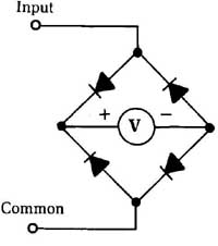
-- Fig. 1 This circuit makes it easy to test voltages of any polarity, either
dc or ac. Input
The bridge configuration of the diodes rectifies an ac voltage into a more or less equivalent dc voltage that can be read by the dc voltmeter. Moreover, if you reverse the polarity of the test leads when you are measuring a dc voltage, the diodes automatically compensate and correct the polarity as far as the voltmeter. No matter if the test signal is ac, positive dc, or negative dc, the volt meter always “thinks” it sees a positive dc voltage.
This method is handy, but please don’t expect miracles. This is a very crude trick, with a number of significant limitations. Don’t use it in any application where precise voltage values are crucial.
Measurements of ac voltages are particularly likely to be in accurate. You’ll get the best results if the ac voltage is in the form of a sine wave. For ball-park voltage readings, however, this simple all-polarity voltmeter works well.
Even with dc voltages, there is some inaccuracy. The voltage drop across the diodes will be subtracted from the signal voltage before it reaches the voltmeter for measurement. At least, this effect will be fairly constant, and, if necessary, you can easily add a constant “fudge factor” to all voltage readings to compensate for the diode voltage drops.
Another limitation of this circuit is that it doesn’t give you any indication of which type of voltage you are monitoring. You can’t tell from the voltmeter if you have an ac voltage, a positive dc voltage, or a negative dc voltage. Still, this circuit is so simple and inexpensive, and can come in so handy for many practical testing situations, that this project is certainly worthwhile. Sure it’s a “quick-and-dirty” trick, but sometimes that’s all you need to do the job.
Polarity indicators
Occasionally, when you are working on an electronic circuit, you might not be too sure of what type of signal you might find at a given test point. Is it ac or dc? If it’s a dc voltage, then what is the polarity — positive or negative?
Of course, you can find out with a little careful trial and error, using your multimeter. This is a rather inelegant solution and calls for a lot of extra test-lead swapping and resetting of the multi-meter’s mode selector switch.
The simple circuit shown in Fig. 2 unambiguously tells you what type of voltage you are dealing with. A suitable parts list for this project is given in Table 1.
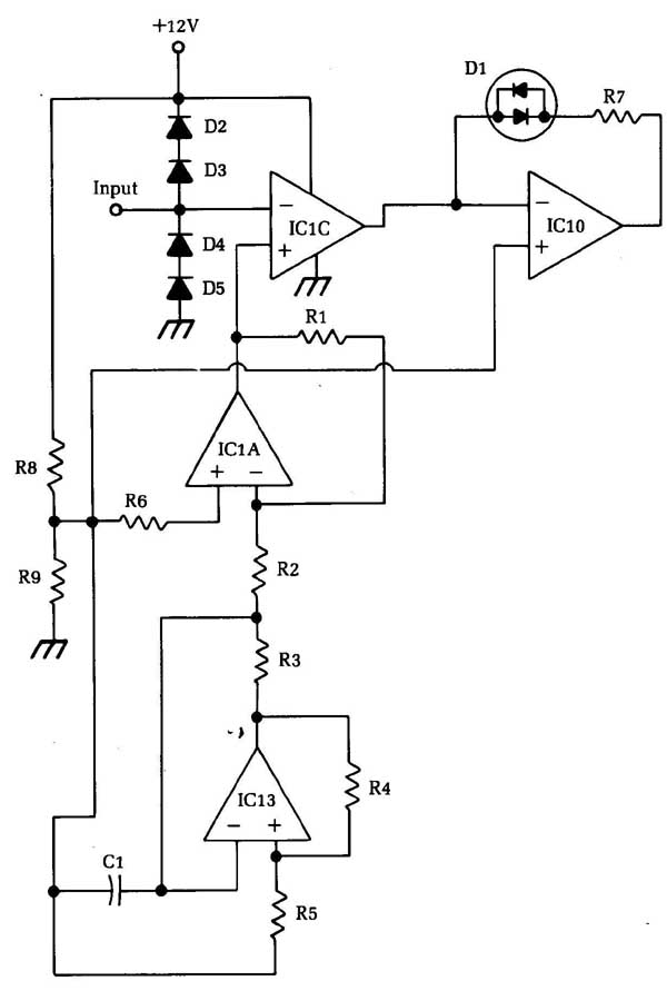
Fig. 2 This circuit unambiguously indicates the polarity of the unknown voltage.
Table 1 Parts list for the polarity indicator circuit of Fig. 2.
IC op amp
D1 tri-state LED
D2-D5 diode (1N4148, 1N914, or similar)
C1 0.01 uF capacitor
R1 1 M-ohm ½ Watt 5% resistor
R2, R6 330k-ohm ½ Watt 5% resistor
R3, R4, R5, R8, R9 10k-ohm ½ Watt 5% resistor
R7 470 ½ Watt 5% resistor
Four op amp stages are employed in this circuit. Any garden-variety op amp chips can be used in this application. To keep the finished device as compact as possible, a quad op amp chip is probably your best choice, since all four op amp stages are contained within a single chip. The LM324, which contains four 741 type op amps, will work just fine in this circuit.
The most crucial component in this project is the indicator LED (D3). Notice that this is a tri-state LED, which contains two LED elements of opposite polarity in a single housing. These two LEDs have contrasting colors, usually red and green. With a dc voltage of one polarity, the LED will glow red. If the dc voltage’s polarity is reversed, the LED will glow green. If an ac signal is applied to the tri-state LED, the two elements will blink on and off at a rate too fast to be visible. The red and green glows will blend together, and the unit will appear to have a yellow glow.
In a pinch, you could use two separate LEDs. An ac voltage would be indicated when both LEDs appear to be lit simultaneously (actually they are blinking on and off at a very rapid rate). This is a rather inelegant solution, however, and tri-state LEDs really aren’t all that expensive or difficult to find.
The first and second op amp stages form a simple signal generator, putting out a sawtooth or ramp waveform. The third op amp stage serves as a simple comparator. The output of the ramp wave generator is compared to the input signal. Diodes D1 and D2 force the input signal into the operating range of the circuit, al though a severe overvoltage can still damage the circuitry. The output of this comparator stage is fed into a second comparator, the fourth and final op amp stage. This signal is compared to a reference value of half the circuit’s supply voltage. The values of resistors R1 and R2 must be equal for this purpose.
If the input signal is a positive dc voltage, the LED will glow red. If the input signal is a negative dc voltage or an ac voltage, the LED will glow green. Of course, if the LED doesn’t light up at all, there is no signal (or a ground potential signal) at the test point.
Full-wave power supplies
Figure 3 shows a full-wave rectifier power supply with a step- up power transformer. This type of circuit is used in many TV, PA, and radio circuits.
To read the supply voltage for the TV or amplifier (or the load), put the positive lead of the voltmeter on the filter output, which is one terminal of the choke (coil). Always set the meter to a scale that will show more than the voltage you expect to read. In typical TV circuits, this is between 300 and 500 V. Start with the meter on a 0 V to 500 V dc scale.
Notice one odd thing: while putting in 300 Vac at the trans former secondary, you get 350 Vdc at the filter input, after rectification. This apparent voltage increase is caused by a difference in the way the voltmeter reads ac and dc. Ac voltage is read as an effective or rms, which is only 0.707 of the actual peak or maximum voltage in the waveform. (Conversely, the peak value is 1.414 times the rms value.) By rectifying the ac voltage, you get a series of dc pulses that reach the peak value of the input voltage. Here, this would be 300 X 1.414 or about 420 V.
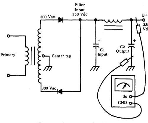
Fig. 3 A full-wave rectifier power supply with a step-u p power trans
former is used in many TV, PA, and radio circuits. Filter; Input 350 Vdc; Primary
When you feed this pulsating dc voltage to the large electrolytic input filter capacitor C1, it charges the capacitor to the peak voltage, less the “rectifier drop.” The exact amount of voltage dropped across the rectifiers will depend on the characteristics of the specific devices used. For convenience, assume the rectifier drop is about 50 V. When drawing current out of the power supply to feed the load, this drops the voltage a little more, so you end up with about 350 Vdcat the filter input. Drawing the load current through the filter choke gives a small voltage drop, so you read about 335 Vdc at the filter output.
In some circuits, you’ll find resistors used in place of the choke. The higher dc resistance makes the drop within the filter higher, so you get a lower voltage at the filter output.
Measuring ac voltages
AC voltage tests are inherently trickier than comparable dc volt age tests. The waveshape (harmonic content) and the frequency of the signal being measured both can affect the reading obtained on a multimeter.
If at all possible, ac voltages should be measured with an oscilloscope, rather than a multimeter. On an oscilloscope you can actually see the waveform and the frequency, and you can measure the peak to peak voltage by counting the number of granules taken up by the height of the displayed signal. You can get reasonable accuracy on your measurements this way, al though you can’t really get high-precision results. Typically, the accuracy of ac voltage readings made on an oscilloscope are about 3 to 5 percent, which is pretty good, although not great.
If you need greater accuracy and the waveform in question is reasonably close to a sine wave, you can measure the signal with the ac voltage section of your multimeter. However, if any other waveform is involved, you won’t be able to get meaningful readings.
Check the manufacturer’s specification sheet for the multi meter you are using to make sure the frequency of the signal to be measured is within the usable range. A too high or too low signal frequency will throw off the reading, often by a considerable amount. Some simple, inexpensive multimeters can’t deal with frequencies much higher than about 40 to 60 Hz. But modern high-grade DMMs often can handle frequencies up to about 10 kHz (10,000 Hz) on the lowest voltage range. Of course, if the ac signal is riding on a dc voltage (not centered around ground potential), you won’t be able to get an accurate reading from a multimeter.
If you need to measure a moderately low-frequency square wave, you can use the dc voltage section of your multimeter. The reading will be approximately one-half the actual (peak) voltage value. For example, a reading of 2.5 V would indicate a measured signal voltage of about 5 V.
This trick will only work with a fairly narrow range of frequencies. You will have to experiment to determine the useful limits of this test on your particular multimeter. If the signal frequency is too low, an analog meter’s pointer will bob back and forth, making it very difficult, if not impossible, to read. On a DMM, you would just get a blur of continuously changing numbers, not any useful measurement. On the other hand, if the signal frequency is too high, you will get a steady reading, but it will be come increasingly inaccurate as the frequency increases.
Power supply ripple
Many modern electronics circuits require a fairly tightly regulated power supply. That is, the supply voltage should not vary much from its nominal value. Except for battery-operated portable equipment, most electronic devices are operated from the ac power lines through an ac-to-dc converter power supply circuit. Ordinary house current has a frequency of 60 Hz. All too often, some of this 60 Hz ac signal will manage to get through the power supply’s filters and ride on the dc supply voltage, as illustrated in -- Fig. 4. This effect is known as power supply ripple.
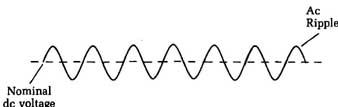
Fig. 4 Some circuits are sensitive to power-supply ripple, which is an
ac signal riding on the dc supply voltage. AC Ripple; Nominal DC voltage
Of course, it’s quite easy to spot such ripple with an oscilloscope, but when you are working on a power supply circuit, it probably is easier to use a multimeter. First, measure the dc volt age at the output of the power supply circuit, then switch your multimeter into the appropriate mode to measure ac voltages. Note: Please remove the test leads from the circuit under test or turn off the power to the system while switching modes. In some cases, your multimeter could be damaged if power is applied continuously to its test leads while you are switching modes.
Measure the ac voltage at the same test point where you took the dc voltage reading. This ac voltage will be roughly equivalent to the ripple signal riding on the dc voltage. It usually will be a very small value, unless there is something severely wrong with the power supply circuit. It certainly should be considerably lower than the dc voltage.
Divide the ac ripple voltage by the dc voltage and multiply by 100. In algebraic terms this is:
Eac/Edc X 100 = % ripple
where Eac is the ac voltage, and Edc is the dc voltage.
As an example, let’s assume the power supply is putting out a dc voltage of 12 V. The ac ripple voltage is 0.15 V, so the power supply’s ripple rating in this case works out to:
% ripple = 0.15/12 x 100
= 0.045 X 100
= 4.5%
This is quite a good reading and should be perfectly sufficient to power most electronic circuits adequately. However, some highly crucial circuits (such as some digital systems) might re quire even better regulation. You will need to add more filtering to get good results from the circuit using this power supply in this case.
Let’s consider another example. This time the dc voltage is 9 V, and the ac ripple voltage gives a reading of 1.2 V. This means the ripple factor of this power supply works out to:
% ripple 1.2/9 x 100
= 0.133 X 100 = 13.3%
This much ripple is likely to cause some operational problems for all but the most non-crucial circuits. Assuming the power supply circuit wasn’t just from a lousy design, there is probably a bad filter capacitor in the circuit. This is a fairly common type of problem, especially with older electronic equipment. It also can happen occasionally with equipment that has been left unused for an extended period. Large electrolytic capacitors are commonly used for power supply filtering. They can sometimes dry out and go bad if not occasionally refreshed by a suitable voltage being fed across them.
If the ripple factor is really outrageously large in proportion (say, about 25% or greater) to the dc voltage, suspect that one or more of the rectifier diodes in the power supply circuit has opened up or you have a bad transistor or voltage regulator IC. Such problems almost certainly will create severe mis-operation of the circuitry being powered by the defective supply. In many cases, the result could be complete equipment failure. Fortunately, this type of problem is not too common.
==Shorted power transformers==
A common source of problems in electrical circuits is the short circuit. The trick is in determining just where it is. It’s usually somewhere in the load circuit, but not infrequently, the problem might be in the power transformer. You could waste hours going through every component of the load circuit and tearing your hair out because everything checks out fine, when the problem was really in the power supply itself.
A handy “quick-and-dirty” test is to disconnect everything from the secondaries of the power transformer. It should be driving no load at all. Now, plug in the device and wait a few minutes. Ten to twenty minutes would be appropriate. Feel the case. Is it abnormally warm? If it is, then the power transformer is probably shorted. If the case is too hot to touch comfortably, then there is definitely a problem with the power transformer.
You’ve narrowed down the problem to the power transformer, since nothing else is getting power, so no other component can be the source of the heat. The transformer cannot be overloaded, since it’s running with no load at all, so the current drawn from its secondaries should be zero. The only possible cause is some shorted windings within the transformer itself. The transformer must be replaced or rewound.
You can use a dynamometer-type wattmeter for a more exact test. A good power transformer with no loads should give a very small reading, of 5 W or less. This small wattage is caused by the normal iron-loss effects within the transformer. A higher wattage reading with no load is a clear indication of trouble.
Not all wattmeters will work properly for this test. You must use a dynamometer type, with both a voltage coil and a current coil. Such a wattmeter will have four terminals, instead of just two.
What if you don’t have a suitable wattmeter handy? You can make a simple, crude, but effective wattmeter with an ac volt meter (the ac voltage section of your multimeter) and a 1 ohm resistor in series with the ac circuit to be monitored.
==Power supplies with voltage dividers==
In actual circuits, you need to divide the V+ voltage to get the proper values on the different circuits. Therefore, you must use a circuit called a voltage divider. Such a circuit is shown in Fig. 5. With the V+ voltage from the full-wave power supply just discussed, all we need to do is make the + and - connections to the divider.
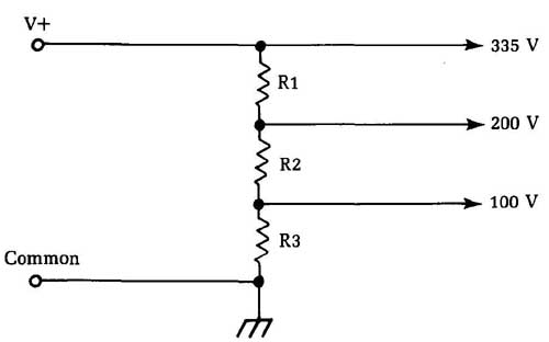
Fig. 5 This power-supply circuit includes a voltage divider to supply different
voltage values to various portions of the load circuit.
When hooking the series of resistors across the supply, you get a small, constant current flow in the resistors. This bleeder current helps to stabilize the voltage by furnishing a constant load on the supply. You can tap off any voltage you need by tapping down on the voltage divider.
You’ll find a lot of variation in resistance values used in voltage dividers, but the total will probably be somewhere around 40 to 50,000 1 The total resistance is chosen so the bleeder current won’t be too high, which could overload the power supply. The values of the individual resistors are chosen to divide the total voltage as desired.
To check the resistors, put the negative lead of the voltmeter to ground, and read the voltages at the taps. For instance, you might get something like this: The 335 V tap reads 345 V; the 200 V tap reads 210 V; the 100 V tap reads 0. What’s the trouble? R2 is open. Note that the taps that still read voltage have higher readings than normal. This means that part of the normal load has been lost. The bleeder current has also ceased, since the circuit from which V+ to ground is open, which raises the voltages still more. Double-check by turning the set off and checking the resistance of R2 with an ohmmeter.
Now let’s se what happens if we find almost the same symptoms as in the preceding unit. Suppose the 335 V tap reads 320 V, the 200 V tap reads 180 V, and the 100 V tap reads 0 again. Note that these voltages are now lower than normal. You’ll notice another typical symptom if you touch the resistors: R1 and R2 are now very hot, and R3 is cold.
If you turn the set off and take resistance readings, all of the resistors themselves are correct; however, when you read the resistance from the 100 V; tap to ground, there’s a 0 reading. There is the trouble! Check the bypass and filter capacitors in the circuit; one of them has shorted out.
The key clues, other than the overheating of the other resistors, are the low voltages. When the capacitor shorted, it took R3 out of the circuit completely. As a result, there is that much less resistance from V+ to ground, so the bleeder current will go up and the total voltage will go down. In many cases, this kind of overload Will be enough to burn out R1 or R2. So if you find an open resistor at any point in a voltage divider circuit, check on its load side (the end away from the source of voltage) to make sure that there is no short circuit there that could burn out a newly in stalled resistor.
Power supplies with dropping resistors
Figure 2-6 shows the equivalent of the previous circuits, but with the resistors arranged a little differently: individual resistors are connected into each voltage-supply circuit. The result is the same — each circuit gets its proper voltage. Without the multiple-tapped voltage divider resistors, there is no bleeder current in such a circuit.
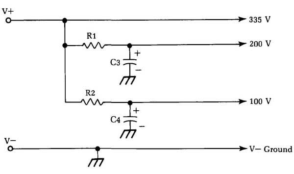
Fig. 6 This power-supply circuit features dropping resistors.
The dropping resistors are chosen so that their values will give the correct voltage to each circuit. This feature gives a very good clue when there’s trouble. If the voltage on any tap is low or high, then check that circuit first to see why. The rest of the volt ages won’t be affected as much, but will be changed to some ex tent.
First check the supply voltage (this rule holds for all power- supply troubleshooting). Without the right supply voltage, the other voltage measurements are meaningless. Use some of the same obvious clues as before. For example, if some of the drop ping resistors are very hot and the supply voltage is low, you know immediately that there’s a short circuit somewhere.
If the supply voltage is low, but there are no signs of over heating, then look for something that is weak — a leaky or shorted diode, an open input filter capacitor, a weak selenium rectifier, or anything that would reduce the ability of the power supply to de liver the right amount of current.
These tests apply to all circuits. In the circuit shown, a short in one load circuit will kill the voltage at that tap, but it won’t make the others drop as much as before. For example, if C3 is shorted, the 200 V line will read 0, the 335 and 100 V lines will go down by about 10 percent. The key clue will be R1; it will be very hot. If the short has existed long enough to cause R1 to burn out, then the 200 V line will read 0, but the other voltages will be above normal because of the loss of the normal load current in the 200 V line.
Many sets use this circuit. The average dropping resistor will be a 2 W carbon type. If it’s been overheated, you’ll notice a decided change in its appearance. The case will be darkened and the color-coding paint will have changed color because of the heat. The red bands, if there are any, are particularly valuable as indicators. They are the first to show a change of color from overheating and usually turn a dark brown.
Check any resistor that shows signs of overheating. In fact, it’s a good idea to replace it on general principles because the overloading might have changed the resistance value.
Power-supply circuits with branches
Figure 2-7 shows a power-distribution circuit that can be found in all types of electronic equipment using either transistors or tubes. The main differences between the tube and transistor circuits are in the resistor values and the voltages. Voltages typically range from 30 V to 40 V for transistors and up to 300 V or 400 V for tubes.
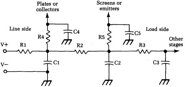
Fig. 7 A power distribution circuit like this one is used in many types
of electronic equipment. Plates or Screens or collectors emitters; Line side
V+ R1; Load side; C1; Other stages; C2
In Fig. 7, the supply point (V+) is again at the left-hand side, V- is ground. The current goes through R1, then branches through R2 and R4; the current through R3 goes on to other circuits. Each junction point is bypassed by a capacitor which is absolutely necessary to keep the RF impedance of the power supply very low. Since this distribution circuit is common to all stages, it must prevent any interaction between the various circuits. If not, you get feedback and the equipment will oscillate.
The capacitors are the most common cause of voltage troubles. If any of them shorts, it will kill all voltages past the point where it’s connected in the circuit. However, there’s a quick and easy way to find a shorted capacitor.
In Fig. 7, V+ is the supply side or line side of the network. The right-hand side of the circuit is the load side — the stages that need the voltage. If you know where the current is coming from and what it goes through on the way, you can tell what’s wrong when it doesn’t get to where it should!
For instance, if C2 shorts, you’ll read 0 Vat the junction of R2, R3, and R5. Clue No. 1: Voltage is present at the junction of R1, R2, and R4, but it isn’t as high as it should be. Clue No.2 is easy to spot:
R2 is probably getting very hot. R3 and R5 are cold. So look on the load side of R2 for the short. The current must go through the last hot resistor in the circuit before it gets to the short. Turn the power off and take an ohmmeter reading. Look for a zero resistance to ground; such a reading is always incorrect in a voltage supply circuit, so there’s the trouble. To confirm this diagnosis, disconnect C2 and check it. The short disappears from the resistor network, and C2 shows a high leakage or short.
When you’re hunting for a short in the power supply, start at the power supply (V+) and go from there toward the load(s). Remember this procedure because it’s always the easiest way to find the cause of the trouble. Use the schematic diagram. Trace the power-supply circuits to each stage through the dropping resistors past any bypass capacitors that could short out until you get to the point where there’s no voltage.
Transformer-powered circuits have normal resistances of about 20,000 ohms to ground. This is mainly the leakage resistance of the electrolytic filter capacitors. In silicon-rectifier or voltage- doubler circuits, you might have to disconnect the rectifiers. They offer a very low back resistance that can falsely indicate a short circuit.
Another quick check is to simply disconnect some of the loads and see what happens. If the supply voltage suddenly jumps back to normal, the last load disconnected could be the trouble spot. Also, you can make mental additions of the various dropping resistors in the circuit by checking their values on the schematic; take resistance readings at each end of the circuit and compare. In -- Fig. 7 , for instance, if all resistors were 1,000 ohms, and C1 was shorted, you’d read 1,000 to ground from V+ and 2,000 to ground from the load end of R3 (R2 + R3).
Transformerless power supplies
Many types of equipment now use transformerless power sup plies for economy. Instead of stepping up the ac voltage with a transformer, apply the line voltage directly to a rectifier at the standard value of 117 V rms. Actual line voltage might vary, of course, but most equipment is designed to work, as stated on the rating plate at “105 to 120 Vac.”
Figure 2-8 shows the simplest possible circuits: a half-wave rectifier and filter circuit (the filter is the same as before). In this circuit, again, the dc voltage is higher than the ac input. With a 117 Vac input, there’s about 145 V at rectifier and about 135 Vat the filter output. The input capacitor (C1) will be a large electrolytic, usually from 60 to 100 microfarad (uF). A resistor of about 1,500 uF is used as a choke.
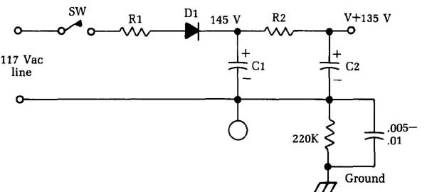
Fig. 8 The simplest possible transformerless power-supply circuit is a
half-wave rectifier and filter.
To measure dc voltages in this circuit, take the readings be tween V+ and A -. Measurements between V+ and ground won’t be accurate because of the large series resistor. One fast way to find the negative terminal is to put the voltmeter negative prod on the negative terminal of the electrolytic capacitor. In can-type electrolytics (with one exception) the can is always negative. In cardboard-tube types, the black wire will be the negative if standard color coding is used.
Half-wave voltage doublers
The 135 V from a simple transformerless power supply isn’t high enough for TV circuits, so a circuit is needed that will give a higher voltage. Such a circuit is the voltage doubler, shown in Fig. 9. There are several types of voltage-doubler circuits, but this one is the most popular, probably because it’s the simplest. It’s called a half-wave voltage doubler because it uses each half of the incoming line voltage to charge a separate capacitor. The two capacitors are then discharged in such a way that the voltages add up. This is the basis of all voltage-doubling circuits.
Although we are told that an electrolytic capacitor should never be connected to the ac line, here we seem to have one hooked right to it: C1 is in series with the ac input. However, following the return circuit, notice that the capacitor is never subjected to a true alternating voltage. On the first half-cycle of voltage, the polarity is such that D1 is conducting. Current flows into C1, then out through Dl, which is the “shunt” rectifier, and back to the other side of the ac line (note that this is a unidirectional current). When we say that current flows through C1, we mean only this one-direction charging current. Such a current flows in all capacitors while they are charging to an applied volt age.
Now, C1 is charged to about 135 V, and the next half of line voltage has such a polarity that D1 is not conducting, but D2 is. So, the current from the line flows on through D2 and charges C2; at the same time, C1 discharges through the same circuit, and its voltage is added to the charge on C2 because the polarity is the same (positive with respect to B—), C2 charges up to double the line voltage and you get about 270 V instead of the 135 V that was in the ordinary half-wave rectifier circuit.
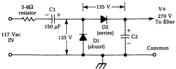
Fig. 9 A voltage doubler is used to obtain a higher supply voltage.
The voltages here are read to an isolated common point, as shown. The most important thing to look for in such voltage readings is balance. If both rectifiers and both capacitors are good, you will be able to read the dc voltages as shown: 135 V across Dl, from common to the center tap of the two rectifiers, and an equal 135 V directly across D2, from center tap (place the negative meter lead here) to positive of V+. If you read 135 V across one rectifier and only about 80 V across the other, the chances are that the “low” rectifier is faulty.
If the input capacitor loses capacitance or opens; the dc volt age will drop to less than half normal or disappear entirely. If C2 opens or loses capacitance, the dc voltage will drop quite a bit and there will be a great increase in the hum level.
The small resistor seen in the ac input is called a surge resistor and is a fusible type; although it’s a wirewound resistor of about 4 to 5 watts in rating, it’s designed to act as a fuse. If something shorts out in the power supply, it will open and prevent further damage. (A good check for this resistor in actual circuits is to care fully feel it after the set has been on for a minute or two. If it’s warm, it’s okay. If it’s “stone cold,” it’s very apt to have been blown.)
This is the instance mentioned earlier where the can or negative terminal of an electrolytic capacitor is not common. Notice from the circuit that both sides of C1 are “hot” with respect to the common, and practically everything else!
Because of the pulse nature of the current and voltage across C1, it’s very difficult to check this capacitor with a voltmeter. The symptom of an open C1 is a large drop in V+ voltage; the quickest test for this condition is to shunt a known good electrolytic capacitor of about the same size across it. Hook your dc voltmeter to the output with test clips, note the reading, and then shunt the test capacitor across C1; if the dc voltage jumps up to normal, replace C1. You don’t have to use the same size capacitor for testing. If you re place a capacitor, always use exactly the same size; but almost any size capacitor will do for a quick test. (If C1 is 150 uF, as many are, you can shunt, say, an 80 unit across it; a very definite rise in the dc voltage indicates that the original capacitor is bad.)
Full-wave voltage doublers
The full-wave doubler, illustrated in Fig. 10, is the original volt age-doubler circuit. It was used with special dual-diode vacuum tubes in old radios and is now found in quite a few circuits with selenium or silicon rectifiers, as shown here. To make the circuit easier to read, it’s shown fed by an isolated transformer secondary winding—a circuit that you’ll find in actual equipment in many cases. In a few cases, this circuit is used without the isolation transformer—not too many, though, because the floating center tap makes it hard to handle with respect to the rest of the circuits.
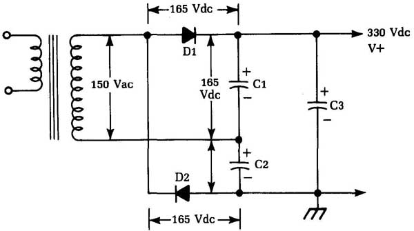
Fig. 10 A full-wave voltage doubler circuit.
It works like this: On the first half-cycle of voltage from the ac supply, D1 conducts and charges C1, just as in the half-wave rectifier circuit. Because D2 is reverse-biased during this time, it does nothing. On the next half-cycle, the polarity reverses; D2 con ducts and charges C2, and D1 is cut off. Now two big electrolytic capacitors, each one charged to 165 Vdc, are connected in series. So, you can take the “added” voltages off and feed them to the filter as the sum, or 330 Vdc. The action of this circuit depends on the alternate-charging and series-discharging of these two capacitors. This is the basis of all voltage-doubling circuits, but it’s not so apparent in the others. Here, notice the two separate capacitors.
Tests are the same as in the half-wave circuit. Read the dc voltage across each rectifier, watching your voltmeter polarity; the reading should be 165 Vdc on each one. The same goes for capacitors C1 and C2: the voltages must be equal because the capacitors are to be the same size. The dc output voltage is the sum of the voltages across the two capacitors. C3 is the filter capacitor.
If one of the doubler capacitors should lose capacitance or open, the circuit won’t balance and the output voltage will drop quite a bit. The same thing happens if one of the rectifiers goes bad. As mentioned, the doubler capacitors must match; you’ll find sizes from 40 to perhaps 200 UF used here. The size of the doubler capacitors affects the developed dc voltage. As a rule, the bigger the doubler capacitors, the higher the dc voltage, because larger capacitors will hold more charge.
The filter capacitor, C3, has nothing to do with the doubling action; similarly, the doubler capacitors have very little to do with the filtering. So if you have a bad hum with almost normal output dc voltage, the filter capacitor is weak. If you have some hum and the voltage is low (more than 25 percent), one of the doubler capacitors has probably gone weak or open.
In the isolated circuit shown in Fig. 10 the common point can be grounded to the chassis. Inline-connected circuits without any isolation, both the capacitor center tap and common must be isolated from the chassis, as in the half-wave circuit. This can be confusing when you are taking dc voltage readings, so watch out. Always connect the negative lead to the voltmeter to the negative terminal of the filter capacitor, not to one of the doublers, unless you are sure that you are on the negative terminal of C2.
Full-wave bridge rectifiers
Figure 11 shows a common circuit you’ll find in color TV, two-way FM transmitter-receiver power supplies, and many other applications, including low-voltage supplies for ac power of transistorized equipment. This circuit is a full-wave bridge rectifier. It has many advantages. Notice that the isolation transformer needs no center tap. So, the full secondary voltage is available at the rectifier output, rather than half of it, as in the center-tapped full-wave rectifiers seen previously. This arrangement saves both size and cost in the power transformer. The circuit can be made fully isolated, and B— is usually the chassis.
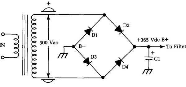
Fig. 11 Full-wave bridge rectifier circuits are used in many types of electronic
equipment.
On one half-cycle, one end of the secondary winding is positive. The other end is negative. Current flows through Dl and D4 to the load and ground, respectively (in the same direction with respect to the load), while the other two rectifiers reverse polarity and don’t conduct. On the next half-cycle, Dl and D4 reverse- bias and cut off, and current flows through D2 and D3. So, it uses both halves of the cycle, as in the full-wave circuit shown earlier.
One advantage of the bridge circuit over other circuits is that there are always two rectifiers in series across the total ac voltage of the secondary. Thus , for a given output voltage, the individual rectifiers have a lower peak voltage applied to them than in other circuits. As a result, they have longer life expectancy, can use lower ratings, etc. The ripple frequency is 120 Hz, as in other full- wave circuits.
When making replacements, look for the identification on the rectifier. Notice that there are two positives hooked together and two negatives. They are always B+ and B—, respectively. Each end of the transformer winding always gets one positive and one negative (it doesn’t matter which of these is which). In some circuits, you might find bias resistors connected between B- and chassis ground. They work in exactly the same way as in the previous full-wave circuits.
The dc output voltage is related to the ac input voltage as it’s in the full-wave tube-type rectifier circuit, except that in the bridge circuit the entire secondary voltage of the transformer is the ac input. If you have a 300 V rms ac supply to the bridge, you will read the same proportion of increase as before; so, you get about 365 Vdc at the filter input, read between B+ and ground or B- in the circuit shown.
This dc voltage is developed by charging C1, the input filter capacitor, to the peak voltage of the rectified ac output, just as in all other rectifier circuits. If the output voltage is low, check this capacitor first. Once again, hook the dc voltmeter to B+, and then shunt a good electrolytic capacitor across C1. If C1 is low in capacitance, you’ll see the voltage jump back up toward normal. If C1 is completely open, your dc voltage will probably read about 40 to 50 percent of normal, or even less, depending on the load current being drawn.
In solid-state circuits, a special bridge rectifier is often used. The four diodes making up the bridge are packaged in a single unit. Such devices function exactly the same as separate diodes.
Electrolytic capacitors in series for higher working voltage
Figure 12 shows the basic schematic of a circuit that you will find now and then in high-powered amplifiers and in a few transmitters. Notice that the filter circuit has a choke input for better voltage regulation. This choke input cuts down on the peak volt age but helps to hold the output voltage much steadier.
In this circuit, we’re getting into V+ voltages that are above the normal working voltage of electrolytic capacitors. The aver age TV filter capacitor is rated at about 450 working volts, with a 550 V peak surge rating. This means that the capacitor should withstand 450 V—at turn on , for example—without blowing out. This peak rating shouldn’t be exceeded or even reached for more than about 15 to 20 seconds. The working-voltage rating , for the best results and longest life, shouldn’t even be met. A 450 V capacitor , for example, shouldn’t be used in circuits with steady or normal voltages of more than about 400 V, and this is cutting it close. A 450 V capacitor working at about 350 V is about normal in the average well-built TV set or amplifier.
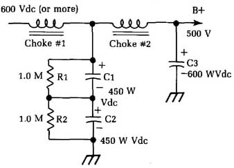
Fig. 12 This circuit is used in some high-power amplifiers.
There are times, however, when you must have an electrolytic that will hold a higher voltage, so put a couple of capacitors in series. This method works just as with paper capacitors; you wind up with half the capacitance and twice the voltage rating. This scheme is used in Fig. 12. Here, C1 and C2 are 450 V capacitors (900 V total) and big enough so that the resultant capacitance is enough to give adequate filtering. In a typical commercial circuit, a pair of 100-pF capacitors is used, giving 50 uF at 900 V.
One thing to remember whenever such units are replaced is the two capacitors must be of exactly the same value for best results. If you use 100 uF and a 60 in series, the smaller capacitor will assume a greater percentage of the total voltage and probably blow! If you have to replace one capacitor of a pair like this, always use an exact duplicate. Actually, if one shorts out, replace both because the remaining capacitor has been severely over loaded and could fail in service soon.
The 1 M-ohm resistors hooked across the capacitors are necessary to equalize the voltages. They take no perceptible current from the circuit because they are so big. They only draw 1 mA of cur rent for each 1,000 V across 1M. So if we had 600 V here and 2 M, our total current would be 0.3 mA (not enough to make the power transformer even run hot.)
Quick check in this circuit: Read the dc resistance from V+ to ground at the rectifier cathodes or filaments. If you read 1 M-ohm, one of the filters is shorted. (You’re reading a short through one and a 1 M-ohm resistance across the good one.) The normal reading, of course, would be 2 M-ohm or less, depending on your ohmmeter polarity. You’ll read a certain amount of leakage resistance through the electrolytics. You must disconnect all loads—including voltage dividers and bleeder resistors, if any—for this test to have any meaning.
AC power supplies for transistorized equipment
Essentially, there are no fundamental differences between ac power supplies for tube-based equipment and those designed for use with transistorized circuits. The same basic circuits are used in both types of equipment. There are differences in the values of voltage and current, however. Tube supplies use high voltages and low currents; transistor supplies use low voltages and high currents. If a TV supply has 350 V output at 250 mA, it draws 87.5 W. A transistor amplifier power supply with a —25 V output at 3.5 amps also draws 87.5 W. There is no difference in the power supplied; only the values of voltage and current are different. As long as their product stays the same, the output power is the same.
In one respect, you need different test equipment for transistor circuits. In tube circuits you measure high voltages; in transistor circuits you often need to measure very small voltages— frequently 0.1 V or so. With tubes, voltage tolerances can be very high. If the rated plate voltage of a tube is 100 V, in many cases it can vary from 90 V to 110 V without making a lot of difference in the output of the tube. (In some circuits, tolerances are as high as 20 or even 25 percent.) Hence, your dc voltmeter can have a fairly large error before it makes any difference in a tube circuit.
Transistor voltages are more crucial for two reasons. First, the levels are only in the range of tenths of a volt; and second, tolerances are much tighter than with tubes. In the bias voltage reading of a typical transistor amplifier, you might find such values as base, 0.4 V; emitter, 0.6 V—giving a 0.2 V difference. Trying to read that on a 5 V range (the lowest on many VOMs) is demanding a great deal from an instrument whose accuracy at full scale might be no better than 5 percent. In the lowest quarter of the scale, it could be considerably poorer. A good VOM for this kind of work should have a 2.5 V (or lower) low range with at least 20,000 per-volt sensitivity and 2 percent full-scale accuracy.
Changes of a fraction of 1 V can come from a variation in the supply voltage. Voltage-regulated power supplies are used quite often in better transistor equipment. Like tube circuits, the cheaper transistor units simply use “straight” power supplies and depend on the regulation of the power line to keep them within limits. Even the best circumstances, however, the ac line voltage varies constantly as its load changes. The use of some kind of volt age regulation makes transistor equipment work much better. Batteries, of course, furnish a steady source of power. In high- quality equipment, such as laboratory-type transistorized volt meters, even the battery supply goes through a voltage regulator!
Transistors are far more sensitive to hum than tubes. Transistors operate on very small voltage changes, which cause very large current changes for a given power output in watts. Since hum is always a voltage phenomenon, you really have to lean over backward to make sure you have taken out every last bit of hum and ripple in the power supplies. Some highly specialized circuits in the next few pages have done so. Voltage regulation serves a dual purpose here; since hum is voltage variation, you automatically take out the hum if you use a regulator that holds the voltage absolutely constant.
Power supplies from a transformer winding on a phono motor
A simple power supply circuit found in a number of small phono graphs with transistor amplifiers is shown in Fig. 13. The novelty is in the use of a separate winding on the phonograph motor, making the motor serve as a power transformer as well. Transistors need low voltages but high currents. So using a power transformer to obtain a suitable supply voltage is much better than the only other method: a dropping resistor in series with the ac line. With a dropping resistor, heavy current changes that occur in transistor circuits would cause the supply voltage to change as well, upsetting the circuits.
In the circuit in Fig. 13, a simple half-wave rectifier is used. In others you might find full-wave rectifiers, bridge rectifiers, and so on. They all work on the same principle as the power supplies discussed earlier.
In a variation of this circuit, used with small one-tube phono graph amplifiers, the filament of the tube is connected in series with the phono motor. The motor, of course, must be specially wound to work on the lower voltage. A typical example of such a circuit uses a 25 V tube in series with a 92 V motor; 92 + 25 = 117 Vac, so the combination can be connected directly across the line. You can always tell by its behavior when this circuit is used; if the tube blows out, the motor stops!
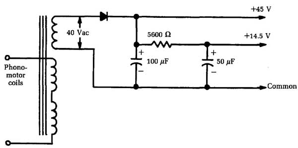
Fig. 13 In some small phonographs, the motor is used as part of the power-supply
circuit. +45 V, Phono motor coils.
Transistorized capacitance multipliers
Transistor circuits need very good power-supply filtering. They also need very good voltage regulation, which is another way of saying the same thing. Very large capacitors help stabilize supply voltages; their charge furnishes extra current when sudden peaks occur in the load current, holding the voltage steady. Even with the large capacitances used in transistor circuits, you can always use more. Figure 2-14 shows a voltage regulator circuit called a capacitance multiplier.
The load current from the power supply flows from the collector to the emitter of the transistor, exactly as in the voltage- regulator circuits. You control the transistor’s resistance with its base bias. You can make the resistance higher for low currents and lower for high currents, thus holding the output voltage steady.
Notice the voltage divider connected between the -11 V supply and ground. The transistor base is hooked to the junction of the two resistors. Under normal load, the base will have a certain voltage (-9.2 V here) that will hold the emitter voltage constant at -9 V. It does so by controlling collector-emitter current or, looking at it another way, by controlling the resistance of the transistor.
If the load current goes up, the bias changes in response. The higher current loads the power supply; the supply voltage drops. The voltage across the voltage divider drops, and the base bias drops with it. This change makes more current flow through the transistor (lowers the resistance); so, there is now a lower voltage drop across the variable resistor and the output voltage is held where it was. (This action occurs in a split second.)
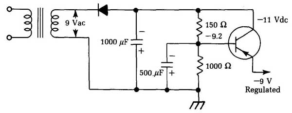
Fig. 14 This circuit is known as a capacitance multiplier.
In effect, the circuit uses the 2 V drop across the transistor as a reserve. When the supply voltage tries to go down, the circuit adds part of this reserve to the output voltage. The reverse is also true; if the supply voltage tries to go up, the transistor takes on a larger surplus.
Why call this circuit a capacitance multiplier? Because of its effect. If you had a very large capacitor across the power-supply output, it would hold a quantity of electrical energy; from this reservoir it could release energy whenever needed to hold the out put voltage constant. The capacitance multiplier does the same thing with a smaller capacitor.
The capacitance multiplication of a given transistor is related to its current gain: the higher the gain, the better the circuit will work. (Current gain is the ratio of a small change in base bias to the corresponding change in collector-emitter current.)
The base capacitor (500 4 in the circuit shown in Fig. 14) plays an important role. By holding a charge, it holds the base voltage as steady as possible. When the supply voltage drops, the base voltage would also drop if it weren’t for this capacitor. The base capacitor discharges part of its energy through the 1,000 resistor, and the resulting voltage drop opposes the supply voltage drop and holds the base at the normal voltage.
Checking capacitance multiplier circuits
To check a capacitance-multiplier operation, check all the dc voltages and compare them with the values given on the schematic diagram. They should be very close. Be sure to check the ac input voltage to see that it’s normal; most circuits are rated at 117 Vac input. Vary the loading. In an audio amplifier , for example, turn the volume full up for maximum load and then all the way off. This variation should have no effect on the output voltage of the capacitance-multiplier circuit.
If the output voltage is low, disconnect the load. If the voltage jumps back up to above normal, there could be a heavy overload of current being drawn by the amplifier — more than the regular circuit can handle. The load current can be measured by putting a milliammeter in series with it at the voltage-regulator output. The proper value will be given on the schematic.
Check the DC voltage between the collector and emitter of the regulator transistor. If this difference is very low, or zero, check the base voltage before you decide that the regulator transistor is shorted. If, in the circuit shown in Fig. 15, the base should be down to about —8 V instead of the normal —9.2 V, the transistor would be conducting as hard as it could in an effort to hold the voltage up. A wrong base voltage could result from changes in the values of the voltage-divider resistors, excessive leakage in the base electrolytic capacitor, etc.
As usual, an alternate trouble can show similar symptoms. Check the control transistor for shorts and leakage. If you’re not certain, take it out and check it with an ohmmeter; all transistors should show the diode effect on each pair of elements. Also, check the schematic to see if there is a shunt resistor connected across the control transistor, as shown by the dotted lines in -- Fig. 15. Such a resistor is used in some circuits to reduce the current loading on the transistor junction. It’s a fairly low-value resistor and of course would upset any in-circuits tests for back resistance be tween collector and emitter leads.
If the output voltage is low—say, by about half the normal voltage — check the input filter capacitor. If this capacitor is open, there will be no reservoir effect, and the output voltage will drop drastically. It’s not a good idea to bridge capacitors for test in transistor circuits; the charging pulse can cause transients that might damage transistors. For safety, turn the set off, clip the test capacitor across the suspected unit, and then turn the set on again. With the instant warmup of all transistor circuits, you won’t lose any time.
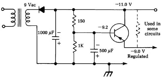
Fig. 15 In some cases, a shunt resistor (shown in dotted lines) is used
in a capacitance multiplier circuit. —11.0 V
If you suspect the rectifier of being weak, use the same procedure. You can clip another rectifier across the original unit— watch the polarity — and turn the set back on. If this action brings the voltage back up, replace the old rectifier. Silicon rectifiers won’t get weak as seleniums do; they usually short out completely when they do fail. You might find one that is completely open, but not often.
Transistorized series voltage regulators
Although the circuit illustrated in Fig. 16 is called a transistorized series voltage regulator, it bears a strong resemblance to the capacitance multiplier just discussed. The only real difference is in the polarity of the voltages. An npn transistor is used here, since the output voltage is positive with respect to ground. The basic action is the same, though, with a few refinements. The collector-emitter “resistance” of the transistor is controlled by the base bias to keep the output voltage at the same level under varying load conditions.
A zener diode is used to hold the base voltage constant. A zener diode acts as a normal diode when reverse-biased until a certain voltage is reached. Then it breaks down and carries a very heavy current. This breakdown is sometimes called a controlled avalanche.
When this conduction occurs, the voltage drop across the diode remains essentially the same over a wide range of current flow. (A protective resistor in series is used to hold the maximum current within safe limits and prevent complete burnout of the diode.) This variable-current-constant-voltage action is the same as that of gas-filled voltage-regulator tubes.
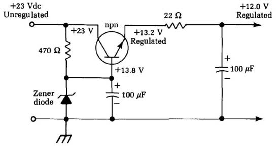
Fig. 16 A series voltage regulator circuit is quite similar to the capacitance
multiplier.
Zener diodes come in many different voltage ratings, which are determined by their construction. To establish a certain reference voltage level, simply choose a zener that has that voltage rating. In the circuit shown, as notice by the base voltage, the diode regulates at 13.8 V. A 100 uF electrolytic filter capacitor helps the zener out a little.
The 22 ohm resistor and 100 uF electrolytic at the right of the figure are not a part of the regulator circuit; the resistor drops the 13.2 V regulator output to exactly 12 V for use by one of the circuits. The electrolytic capacitor is a filter and a bypass capacitor as well, to keep signals from mixing in the power supply and causing feedback or oscillation.
Transistorized shunt voltage regulators
There is one more transistorized regulator that we should mention. You won’t find it used often because its efficiency isn’t as good as that of the series-type regulator. The circuit, called a shunt regulator, is shown in Fig. 17. It’s simple but it tends to waste power.
The operating action of the shunt regulator is the opposite of that of the series type. The regulator transistor (or, in this case, the pair of transistors) is connected across the load in parallel, instead of being in series with it. If the supply voltage goes up, the regulator draws more current, instead of less. This extra current in creases the voltage drop across R1 and brings the voltage back down. The power consumed by the shunt transistor(s) and R1, then, can be said to be wasted.
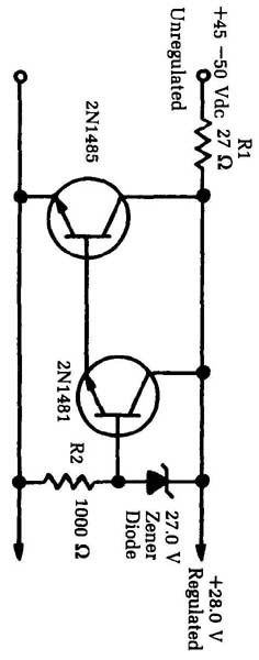
Fig. 17 Some voltage regulator circuits use a shunt, rather than a series
hook-up. Unregulated +28.0 V
The operating principles of series and shunt regulators are similar. The zener diode clamps the base voltage of the transistor. The voltage drop across series resistor R2 is used to signal the regulator when more of less current is needed.
Three transistor voltage regulators for transistor TV sets
Transistor TV sets need very close regulation. The three-transistor circuit shown in -- Fig. 18 is used by at least one leading manufacturer. This regulator uses the same principle as the single transistor circuit presented earlier, but this one is more elaborate. A pair of direct-coupled transistors is used as the regulator, con trolled by an error amplifier. A 47 1 resistor is shunted across the voltage-regulator transistor from the collector to emitter to carry part of the load.
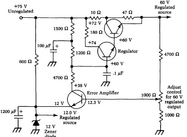
Fig. 18 A somewhat more elaborate voltage regulator circuit. 60 V; Regulated
source +75 V; Unregulated; 1200 pF; Adjust control for 60 V regulated output
The error amplifier makes this circuit quite sensitive to small load-voltage variations. The base is connected to the slider of the voltage-adjust control, which is a part of the voltage divider across the output. In the emitter circuit, a 12 V zener diode clamps the voltage at this value and also provides a 12 V regulated source for some of the TV circuits. The collector is supplied from the 75 V line through the three resistors; it’s also connected to the base of the lower transistor of the regulator. So, the collector voltage of the error amplifier sets the base voltage of the regulators.
If the load current goes up, the output voltage goes down — that is, more negative. The base of the error amplifier also goes more negative. This transistor is an npn unit, so the shift in base voltage changes the bias so that less current flows in the collector- emitter circuit. This circuit includes the three resistors from the 75 V unregulated source. With a lower current flowing through these resistors, the collector voltage goes more positive (it rises), thus making the base of the lower control transistor more positive. It’s another npn, so the positive-going base voltage makes it draw more collector current. This reaction in the lower transistor is transferred and amplified by the upper one; its collector-emitter current increases (or its resistance decreases) and more cur rent is fed to the load circuits, making the voltage rise again. If the opposite happens and the load decreases, making the output volt age rise, just repeat all of this but reverse the polarity of each reaction.
This regulator is adjustable. Using a Variac or adjustable transformer, set the ac input at exactly 120 V, and connect an ac curate dc voltmeter across the 60 V regulated output. With the TV set tuned to a station, adjust the voltage control to make the dc meter read exactly 60 V, and that’s all there is to it. To check operation of the regulator, vary the input ac voltage up and downs V to 8 V from the 120 V level. The dc output voltage should stay at 60 V.
If this test shows too much variation, check the dc voltages on all three transistors. See that the collector voltage of the error amplifier changes as you move the voltage-adjust control. If it doesn’t, go back and check the base voltage of this transistor to see if it’s changing. Make the regular tests for leaky or shorted transistors.
The normal drop between the collector and emitter of the (upper) regulator transistor is 15 V; if this is too low or if there’s no drop at all (output voltage is too high), the transistor could be shorted. Because these are large, bolted-in transistors, they’re not hard to remove for testing. When you return them, however, be sure to get the insulating washers, etc., in the right places.
Transistorized dc-to-dc converters
Rather than having circuits where the ac supplies the power for the transistors, let’s discuss how to make transistors convert dc to ac and then change the ac back to dc at a higher voltage. This is a circuit you won’t see often. It’s used mostly in middle-aged two- way FM transmitter power supplies and in auto radios built during the transitional period before they went all-transistor.
In the original auto-radio power supply, a vibrator interrupted the dc in the primary of a transformer so that you could step up the voltage to the 200 V or so needed for the plates of the tubes. The transistor version does the same thing; it supplies an ac voltage for the primary. You can step it up, rectify it, and come out with a high dc voltage. Transistors produce ac by oscillating. The ac in an oscillator circuit is a good substitute for the interrupted dc from a vibrator (it’s also quieter).
These circuits are usually called dc-to-dc converters when the output is a high-voltage dc. However, there is another popular application; leave off the rectifier and filters and you have ac out. By making the output 117 Vat 60Hz, you can use ac equipment in cars, etc. Such dc-to-ac circuits are usually called inverters or dc/ac converters.
Figure 19 shows a typical dc-to-dc circuit with a common collector connection. This connection could be a transmitter power supply, a supply for a tube-type PA system, etc. The same principle is used in all such circuits. A transistor or pair of transistors is connected to the primary of the transformer. Feedback windings make the transistors oscillate. (This is a blocking oscillator circuit, but other types can be used.)
These oscillators often are run at frequencies above 60 Hz. The higher the frequency, the smaller the transformer can be. Power-line transformers must work on 60 Hz ac; vibrators run at about 115 Hz. You can make transistor circuits run wherever you want, though. Motorola, in some of its two-way radio power sup plies, uses a frequency of about 400 Hz; others have used frequencies up into the thousands of Hz. With high-operating frequency, filter capacitors also can be much smaller for the same filtering efficiency. These characteristics make this circuit ideal for use in mobile and airborne equipment.
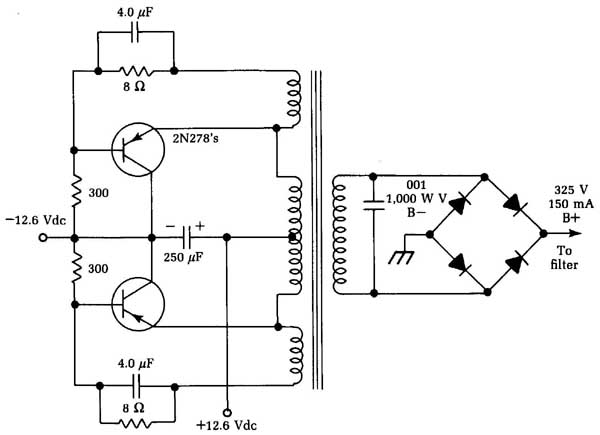
Fig. 19 A typical dc-to-dc converter circuit.
The output of the oscillator is a square wave, which is highly efficient and fairly easy to filter into dc. Bridge rectifiers are commonly used with standard pi-type filter circuits. Another dc-to-dc converter circuit is shown in Fig. 20.
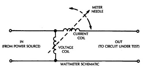
Fig. 20 An alternate dc-to-dc converter circuit is shown here. METER NEEDLE;
- 12.6 Vdc; (FROM POWER SOURCE), CURRENT COIL OUT (TO CIRCUIT UNDER TEST);
WATTMETER SCHEMATIC
Testing dc-to-dc converters
In actual use, the dc-to-dc converter has been a remarkably trouble-free circuit. Some have been known to run for five years or more without ever having problems. However, they’re simple to test. The dc output voltage should be measured first under full normal load, as in all other cases. If the converter is used in a radio transmitter, the voltage should be measured with the transmitter keyed on and tuned for full RF output.
If the dc is low, check the dc input voltage first. In mobile units, make this check in the vehicle with the engine running. Many cases of false trouble have been traced to simple battery drop-off after a long test under power. If the engine is running at a fast idle, the charging system will keep the voltage up to normal as when the vehicle is in actual service. Incidentally, on a 12 V system, this voltage should read almost 14 V. Running the engine can make a big difference in the RF power output of a transmitter. It has been known to bring RF power from 35 W to the full-rated 50 W output.
The AC voltage output from the transformer can be measured if you suspect the rectifiers of being weak. However, since this is a square wave, your rectifier-type ac voltmeter won’t read the true value because it’s calibrated on a sine wave. If it reads about 300 Vac, that’s probably good enough. If so, then the trouble must be rectifiers or filters because the transistors are definitely in oscillation.
If the transistors are not oscillating, check all parts (since there are only five or six, it won’t take long). If either of the 4 uF capacitors in the feedback circuits is open, the oscillator won’t work at all, or not at the right frequency. If it’s trying to run, there will be some ac in the secondary, but not at the right frequency, so the output will be very low.
The output waveform should be in a pretty good square wave, and it must be balanced. If it shows a decided imbalance, one of the transistors is not conducting as heavily as it should. Possible causes are leaky capacitors, leakage in the transistor itself, or an off-value resistor.
The circuits shown use pnp transistors. Npn transistors will do the same job, but the voltages will be reversed in polarity.
IC voltage regulators
More and more pieces of modern electronics equipment are using an IC voltage regulator in their power supplies, especially any equipment with digital circuitry, which requires very precise supply voltages and is very sensitive to power-line spikes.
The internal circuitry of voltage-regulator ICs is not dissimilar to the transistor voltage regulators discussed earlier in this section. Most voltage regulator ICs are three-pin devices, which resemble somewhat oversized transistors, as shown in Fig. 21. The unregulated input voltage is fed in to pin 1, and the regulated output voltage is taken off from pin 3. The middle pin is common to both the input and output circuits. In most cases, the common pin will be connected to ground, although there are some exceptions. The pin order varies among devices, so be sure to check the manufacturer’s data sheet or the schematic.
If you suspect trouble with the voltage regulator, disconnect its output from the circuit being powered. Now measure the regulator’s output voltage. If this voltage is not correct, the odds are strong that the voltage regulator is defective and should be re placed. To be positive, disconnect the unregulated input line from the regulator and measure this input voltage. It should be some what above the desired output voltage, but there might be considerable variation, depending on the specific design. As long as this input voltage is present and “in the ballpark,” it’s probably good and the voltage regulator is the culprit.
To test how well the unit is regulating the voltage, plug the equipment under test into a Variac. Vary the line voltage from about 90 V to 125 Vac to cover the normal range of typical line voltage variation the voltage regulator should be expected to cope with. While varying the Variac’s output, monitor the voltage at the regulator output. This voltage should remain constant (or fluctuate over a very small range). Voltage-regulator problems can cause a variety of symptoms, such as insufficient or excessive gain or parasitic oscillations.
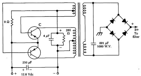
Fig. 21 Most voltage regulator ICs are three pin devices that resemble oversized
transistors.
Reading battery voltages correctly
This section has dealt with reading dc voltages in ac-powered supplies. However, don’t forget the original source of power: batteries. A tremendous amount of battery-powered electronic equipment is in use today, so know how to check batteries correctly.
There’s only one accurate way to read the voltage of a battery—under full load. This is easy; just turn the equipment on before taking a reading! Practically all batteries recover some voltage when the load is taken off. So if you want to know what voltage is present under actual operating conditions, check it with the equipment on and the batteries under load.
Even a dead dry-cell battery will read almost full normal voltage if you check it with a dc VTVM, which places virtually no load on the battery at all. When current is drawn from such a battery, the voltage drops to practically nothing. A brand-new standard dry cell reads about 1.64 V. This drops to about 1.4 V after an hour or so of use and gradually drops lower as the active materials of the battery are used up. When a cell reaches a load voltage of 1.1, it’s considered “dead.” Early battery radios were designed for a cutoff of 1.1V per cell; transistor radios might work a little past this point, but the volume will be fairly low.
Incidentally, dry batteries are figured at 1.5V per cell; so, a 9V battery would be made up of six cells at 1.5V apiece. There fore, cutoff voltage for a 9 V battery would be 6.6 V under full load and so on.
Special battery testers are available. Such a tester is nothing more than a dc voltmeter combined with a shunt resistor to draw current from the battery being tested. A battery tester might be useful at times, but it’s certainly simple enough to just turn the equipment on and read the battery voltage with an ordinary volt meter.
In auto radios and other equipment used in cars, the power comes from the car’s storage battery. Older cars have 6 V systems, and most new cars have 12 V systems. The 6 V type actually reads 6.3 V if the battery is fully charged, and the 12 V system, 12.6 V.
If the engine is running, the generator or alternator should be feeding current into the battery to keep it charged; the system voltage will, therefore, go up. The upper voltage limit is con trolled by the car’s voltage regulator. With the engine running at a fast idle, the voltage shouldn’t go above about 14 V or so. If the voltage regulator isn’t set properly, the voltage can go higher and cause damage to transistors, especially the high-power output types used in car radios now. If the system checks higher than 14 V with the engine running, have the voltage regulator adjusted by a competent mechanic.
The usual vacuum-tube voltmeter uses an input voltage divider whose total resistance is 11 M-ohm Some recent instruments have up to 16 M-ohm ohm input impedance. This resistance remains the same for every voltage range the meter may have.
Transistorized VTVMs have similar input resistance ratings. Field-effect transistors (FETs) often are used in the input circuits because of their high input impedances and because they are true voltage-amplifying devices. Ordinary bipolar transistors are cur rent amplifiers.
The input resistance of the voltmeter might or might not be of significance, depending on the specific measurement being made. In power supplies, batteries, and other low-impedance, high-current circuits, the meter impedance—whether high or low — won’t affect the circuit under test. If the voltage to be read has an ample current reserve, all meters will read the same.
On the other hand, in very high-impedance circuits—such as the plate circuit of a tube where the plate load resistance may be up to, say, 1 M-ohm—meter resistance can make a lot of difference. Let’s take a tube with a rated plate voltage of 50 V, which is supplied from a 150 V source through a 1 M-ohm resistor. Ohm’s law says that this means a normal plate current of .0001 amp, or 100 microamps ( If you try to read the plate voltage with a 1,000 ohm per-volt meter on a 50 V scale, total meter resistance will be 50,000 . Placing this low resistance across the tube results in a shunting effect; current through the plate load resistor will in crease because it now has a 50,000 path from plate to ground. Since it doesn’t take very much current through the 1 M-ohm resistance between the plate and B+ to give a terrific voltage drop, the indicated plate voltage will probably be close to 0!
If you use a 20,000 ohm per-volt meter on a 50 V scale, the meter resistance will be 1 M-ohm Putting this in parallel with the tube, you’d read about three-fourths of the actual voltage, or about 37.5 V. This reading is still not accurate enough, unless you consider the voltage drop caused by the voltmeter.
However, if you hook a vacuum-tube voltmeter with an input impedance of 16 M-ohm across the tube, it’s more accurate. Now that the shunt resistance through the meter is much higher than the effective resistance of the tube, the meter reads much closer to the actual value. In fact, since most voltage readings in such circuits are now made with VTVMs at the factory, you would probably read 50 V.
When testing a circuit, you might find a little box in the lower corner of the schematic diagram showing which type of meter was used in taking the standard test-voltage readings. In some of the older sets, you’ll find that a 20,000 ohm per-volt meter was used —in which case, if you use a VTVM, all voltages will seem high. So, to get an accurate voltage reading, you must always know the test conditions and the type of instrument used to make the standard readings.
Digital voltmeters normally are used in the same manner as VOMs, but in terms of their electrical characteristics they are closer to VTVMs. Digital voltmeters generally feature a very high input impedance—1M-ohm per volt is typical. A digital voltmeter makes precise readings very easy because a numerical value is displayed directly and there is none of the inherent ambiguity involved in determining the exact position of a meter pointer on a scale.
On the other hand, in many cases you need to monitor a continuously changing value. You can monitor the trend of the change easily by watching the up or down movement of a meter pointer, but on a digital voltmeter you would only get a blur of meaningless numbers. The best type of voltmeter to use depends on the nature of the specific application at hand.