AMAZON multi-meters discounts AMAZON oscilloscope discounts
(cont. from part 1)
6. TEMPERATURE TRANSDUCERS
Application of heat or its withdrawal from a body produces various primary effects on this body such as
• Change in its physical or chemical state such as phase transition
• Change in its physical dimensions
• Variations in its electrical properties
• Generation of an emf at the junction of two dissimilar metals
• Change in the intensity of the emitted radiation
Any of these effects can be employed to measure the temperature of a body, though the first one is generally used for standardization of temperature sensors rather than for direct measurement of temperature.
6.1 Resistance Thermometers
Resistance temperature detectors, or resistance thermometers, employ a sensitive element of extremely pure platinum, copper or nickel wire that provides a definite resistance value at each temperature within its range. The relationship between temperature and resistance of conductors in the temperature range near 0°C can be calculated from the equation where R t = resistance of the conductor at temperature t (°C)
R ref = resistance at the reference temperature, usually 0°C
α = temperature coefficient of resistance
Δt = difference between operating and reference temperature
Almost all metallic conductors have a positive temperature coefficient of resistance so that their resistance increases with an increase in temperature. Some materials, such as carbon and germanium, have a negative temperature coefficient of resistance that signifies that the resistance decreases with an increase in temperature. A high value of α is desirable in a temperature sensing element so that a substantial change in resistance occurs for a relatively small change in temperature. This change in resistance (ΔR) can be measured with a Wheatstone bridge, which may be calibrated to indicate the temperature that caused the resistance change rather than the resistance change itself.
Figure 7 indicates the variation of resistance with temperature for several commonly used materials. The graph shows that the resistance of platinum and copper increases almost linearly with increasing temperature, while the characteristic for nickel is decidedly nonlinear.
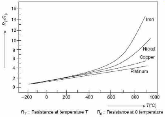
FIG. 7 Relative resistance (R T /R 0 ) versus
temperature for some pure metals
The sensing element of a resistance thermometer is selected according to the intended application. Table 1 summarizes the characteristics of the three most commonly used resistance materials. Platinum wire is used for most laboratory work and for industrial measurements of high accuracy. Nickel wire and copper wire are less expensive and easier to manufacture than platinum wire elements, and they are often used in low-range industrial applications.
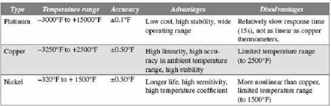
Table 1 Resistance thermometer elements
Resistance thermometers are generally of the probe type for immersion in the medium whose temperature is to be measured or controlled. A typical sensing element for a probe-type thermometer is constructed by coating a small platinum or silver tube with ceramic material, winding the resistance wire over the coated tube, and coating the finished winding again with ceramic. This small assembly is then fired at high temperature to assure annealing of the winding and then it is placed at the tip of the probe. The probe is protected by a sheath to produce the complete sensing elements as shown in Figure 8.
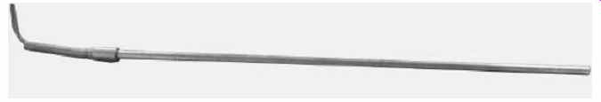
FIG. 8 Resistance thermometer in protecting
cover.
Practically, all resistance thermometers for industrial applications are mounted in a tube or well to provide protection against mechanical damage and to guard against contamination and eventual failure. Protecting tubes are used at atmospheric pressure; when they are equipped inside a pipe thread bushing, they may be exposed to low or medium pressures. Metal tubes offer adequate protection to the sensing element at temperatures up to 100°F, although they may become slightly porous at temperatures above 1500°F and then fail to protect against contamination.
Protecting covers are designed for use in liquid or gases at high pressure such as in pipe lines, steam power plants, pressure tanks, pumping stations, etc. The use of a protecting cover becomes imperative at pressures above three times of atmospheric pressure.
Protective wells are drilled from solid bar stock, usually carbon steel or stainless steel, and the sensing element is mounted inside. A waterproof junction box with provision for conduit coupling is attached to the top of the tube or well.
A typical bridge circuit with resistance thermometer R t in the unknown position is shown in Figure 9 . The function switch connects three different resistors in the circuit.
R Ref is a fixed resistor whose resistance is equal to that of the thermometer element at the reference temperature (say, 0°C). With the function switch in the 'REFERENCE' position, the zero adjust resistor is varied until the bridge indicator reads zero. R fs is another fixed resistor whose resistance equals that of the thermometer element for full-scale reading of the current indicator. With the function switch in the 'FULL SCALE' position, the full scale adjust resistor is varied until the indicator reads the full scale. The function switch is then set to the 'MEASUREMENT' position, connecting the resistance thermometer R t in the circuit.
When the resistance temperature characteristic of the thermometer element is linear, the galvanometer indication can be interpolated linearly between the set of values of reference temperature and full scale temperature.
The Wheatstone bridge has certain disadvantages when it is used to measure the resistance variations of the resistance thermometer. These are the effects of contact resistances of connections to the bridge terminals, heating of the elements by the unbalance current and heating of the wires connecting the thermometer to the bridge.
Slight modifications of the Wheatstone bridge, such as the double slide wire bridge eliminates most of these problems. Despite these measurement difficulties, the resistance thermometer method is so accurate that it is one of the standard methods of temperature measurement within the range -150° to 650°C.
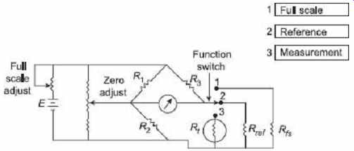
FIG. 9 Wheatstone bridge circuit with a resistance
thermometer as one of the bridge elements.
6.2 Thermocouple
Thomas Seebeck discovered in 1821 that when two dissimilar metals were in contact, a voltage was generated where the voltage was a function of temperature. The device, consisting of two dissimilar metals joined together, is called a thermocouple and the voltage is called the Seebeck voltage, according to the name of the discoverer.
As an example, joining copper and constantan produces a voltage on the order of a few tens of millivolts ( Figure 10 ) with the positive potential at the copper side. An increase in temperature causes an increase in voltage.


FIG. 10 Thermocouple output voltage as a function
of temperature for various thermocouple materials.
There are several methods of joining the two dissimilar metals. One is to weld the wires together. This produces a brittle joint, and if not protected from stresses, this type of thermocouple can fracture and break apart. During the welding process, gases from the welding can diffuse into the metal and cause a change in the characteristic of the thermocouple. Another method of joining the two dissimilar metals is to solder the wires together. This has the disadvantage of introducing a third dissimilar metal. Fortunately, if both sides of the thermocouple are at the same temperature, the Seebeck voltage due to thermocouple action between the two metals of the thermocouple and the solder will have equal and opposite voltages and the effect will cancel. A more significant disadvantage is that in many cases the temperatures to be measured are higher than the melting point of the solder and the thermocouple will come apart.
It would appear to be a simple matter to measure the Seebeck voltage and create an electronic thermometer. To do this, wires could be connected as shown in Figure 11 to make the measurement. This connection of the wires causes a problem of measurement, as shown in Figure 12 .
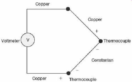
FIG. 11 Effects of additional parasitic thermocouple
Assume that the meter uses copper wires as shown. In this case, where the two copper wires come in contact there is no problem, but where the copper comes in contact with another metal, such as the constantan thermocouple wire, the two dissimilar metals create another thermocouple, which generates its own Seeback voltage. For this example, copper interconnecting wires were used and the thermocouple was copper and constantan. The composition of the wires is immaterial, as any combination will produce these parasitic thermocouples with the problems of additional Seeback voltages. It is an inescapable fact that there will be at least two thermocouple junctions in the system. To contend with this, it is necessary that the temperature of one of the junctions be known and constant.
Therefore, there is a fixed offset voltage in the measuring system. In early times, it is mandatory to place this junction in a mixture of ice and water, thus stabilizing the temperature to 0°C as shown in Figure 13 . In modern-age electronic reference junction is used and it is called the reference or cold junction because this junction was traditionally placed in the ice bath.
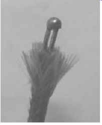
FIG. 12 Connection of wires
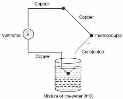
FIG. 13 Application of a reference junction
The classic method of measuring thermocouple voltages was the use of a potentiometer.
This was a mechanical device and is no longer used. Completely electronic devices are used to measure thermocouple voltages and to convert from the Seeback voltage to temperature, and to compensate for the reference junction.
6.3 Errors occurring During the Measurement using Thermocouple
1. Open Junction
There are many sources of an open junction. Usually, the error introduced by an open junction is of such an extreme magnitude that an open junction is easily spotted. By simply measuring the resistance of the thermocouple, the open junction is easily identified.
2. Insulation Degradation
The thermocouple is often used at very high temperatures. In some cases, the insulation can break down and causes a significant leakage resistance which will cause an error in the measurement of the Seeback voltage. In addition, chemicals in the insulation can defuse into the thermocouple wire and cause de-calibration.
3. Thermal Conduction
The thermocouple wire will shunt heat energy away from the source to be measured. For small temperature to be measured, small diameter thermocouple wire could be used.
However, the small diameter wire is more susceptible to the effects. If a reasonable compromise between the degrading effects of small thermocouple wire and the loss of thermal energy and the resultant temperature error cannot be found, thermocouple extension wire can be used. This allows the thermocouple to be made of small diameter wire, while the extension wire covers majority of the connecting distance.
4. Galvanic Action
Chemicals coming in contact with the thermocouple wire can cause a galvanic action. This resultant voltage can be as much as 100 times the Seebeck voltage, causing extreme errors.
5. De-calibration
This error is a potentially serious fault, as it can cause slight error that may escape detection. De-calibration is due to altering the characteristics of the thermocouple wire, thus changing the Seeback voltage. This can be caused due to subjecting the wire to excessively high temperatures, diffusion of particles from the atmosphere into the wire, or by cold working the wire.
6.4 Thermistors
Thermistors (construction of thermal resistor) are semiconductors which behave as resistors with a high negative temperature coefficient of resistance.
Manganese, nickel or cobalt oxides are milled, mixed in proper proportion with binders, passes into desired shapes and then sintered to form thermistors in the form of beads, rods or discs. Sometimes, a glass envelope is provided to protect a thermistor form contaminations.
The resistance R T of a thermistor at temperature T (Kelvin) can be written as where R T and R 0 are the resistances in ohms of the thermistor at absolute temperatures T and T 0. β is a thermistor constant ranging from 3500 K to 5000 K. The reference temperature T 0 is usually taken as 298 K or 25°C.
Now the temperature coefficient of the resistance At T = 298 K, the value of α is …
This is evidently a rather high temperature coefficient because for a platinum resistance thermometer the corresponding figure is 0.0035/°C.
The plot of resistivity (ρ) versus temperature ( Figure 14 ) will also demonstrate this comparison.
Equation (13) can be rearranged to the form where A and B are constants. Eq. (16) may alternatively be used to find temperatures by evaluating A and B from two pairs of known values of R T and T .
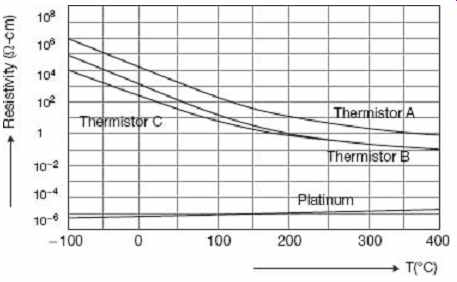
FIG. 14 Comparison of resistivity of platinum
with that of thermistors
Thermistors are very popular as temperature transducers because (i) they are compact, rugged, inexpensive, (ii) their calibration is stable, (iii) they have a small response time, (iv) they are amenable to remote measurements, and above all, (v) their accuracy is high.
Example 2 For a certain thermistor β = 3100 K and its resistance at 20°C is known to be 1050 Ω. The thermistor is used for temperature measurement and the resistance measured is 2300 Ω. Find the measured temperature if the temperature resistance characteristics of the thermistor is given by…
…where T is in Kelvin.
Solution
Here, R 0 = 1050 Ω, T 0 = 293 K. hence from Eq. (15) , we get which gives T = 272.8 K 0°C
Example 3 The resistance of a thermistor is 800 Ω at 50°C and 4 kΩ at the ice-point. Calculate the characteristic constants (A, B) for the thermistor and the variations in resistance between 30°C and 100°C.
Solution
Form Eq. (16) , we get the following conditions:
A + B in 800 =
A + B in 4000 =
which gives A = 7.4084 × 10^-4 and B = 3.5232 × 10^-4 .
The variation in resistance can be calculated from the relation …
7. PRESSURE MEASUREMENT
The pressure, or force, measurement can be done by converting the applied pressure or force into a displacement by elastic elements which acts as a primary transducer. The displacement of the elastic element which is a function of the applied force may be measured by the transducer which acts as a secondary transducer. The output of the secondary transducer is a function of the displacement, which in turn is a function of pressure or force which is the measurand. Some mechanical methods are used to convert the applied pressure of force into displacement. These mechanical devices are called force summing devices.
The most commonly used summing devices are:
1. Flat or corrugated diaphragms
2. Pivot torque
3. Straight tube
4. Single or double mass cantilever suspension
5. Circular or twisted Bourdon tube
6. Bellows
Among these, pressure transducers generally use flat or corrugated diaphragms, bellows, circular or twisted Bourdon tubes and straight tubes. Single or double mass cantilever suspension and pivot torque types are found in accelerometer and velocity transducers. Different kinds of force summing devices are shown in the Figure 15 .
Secondary Transducers
The displacement produced by the action of the force summing devices is converted into a change of some electrical parameter. The various transducers used for this purpose are of the following types:
1. Resistive
2. Inductive
3. Differential transformer
4. Capacitive
5. Photo-electric
6. Piezo-electric
7. Ionization
8. Oscillation.
FIG. 15 Different types of summing devices
7.1 Resistive Transducers
The electrical strain gauges attached to a diaphragm may be used for measurement of pressure. The diagram is shown in Figure 16 . The output of these strain gauges is a function of the applied strain, which in turn, is a function of the diaphragm deflection and the differential pressure. The deflection generally follows a linear variation with differential pressure P = P 2 − P 1 (when the deflection is less than 1/3 of the diaphragm thickness). One of the disadvantages of this method is small physical area is required for mounting the strain gauges. Change in resistance of strain gauges on account of application of pressure is calibrated in terms of the differential pressure. Gauges of this type are made in sizes having a lower range of 100 kN/m^ 2 to 3 MN/m^ 2 to an upper range of 100 kN/m^ 2 to 100 MN/m^ 2 .
7.2 Inductive Transducers
This type of transducers has been successfully used as secondary transducers along with a diaphragm for measurement of pressure. Figure 17 shows an arrangement which uses two coils; an upper and a lower coil which form the two arms of an ac bridge. The coils have equal number of turns. The other two arms of the bridge are formed by two equal resistances each of value R. The diaphragm is symmetrically placed with respect to the coils and so when P 1 = P 2 , The reluctances of the path of magnetic flux for both the coils are equal and hence the inductances of the coils are equal.
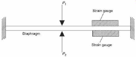
FIG. 16 Differential pressure measurement with diaphragm and strain gauges
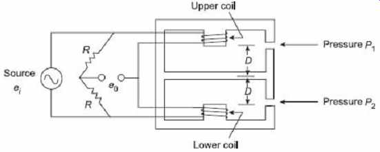
FIG. 17 Pressure measurement with diaphragm
and inductive transducer
Now, I initial self-inductance = N 2 / R 0, where Number of turns, and R 0 = Initial reluctance of the flux path. Under this condition the bridge is balanced and the output, E 0 , of the bridge is zero. Now for any particular moment P 2 is greater than P 1 and therefore the differential pressure P = P 2 − P 1 , deflects the diaphragm upwards through a distance d.
…for small displacement of diaphragms, the reluctance of the flux path of the upper coil is…
R 1 = R 0 + K (D − d ) and that of the lower coil is R 2 = R 0 + K (D + d ). Where K is a constant, D is the initial distance of the diaphragm from the coils and d is the displacement of the diaphragms due to force. Hence, the inductance of the upper coil and that of the lower coil is ...
The bridge becomes unbalanced and the value of output voltage is given by ...
Since K , R 0 , D and e i are constant, the output voltage is directly proportional to displacement d, of the diaphragm. Displacement d , is directly proportional to differential pressure P = P 2 − P 1 Hence the output voltage e 0 may be calibrated in terms of the differential pressure P .
If the value of the deflection d is small then there exists a linear relationship between output voltage e 0 and the differential pressure. It is possible to determine whether P 2 > P 1 or P 1 > P 2 with reference to the phase of the output voltage, e 0 , with respect to source voltage e i.
7.3 Differential Transformers
The linear variable differential transformers (LVDT) is used as a secondary transducer for measuring the pressure with bellows or bourdon tube acting as a primary transducers, i.e., as a force summing device. The pressure is converted into displacement which is sensed by the LVDT and transformed into a voltage. The two arrangements are shown in Figure 18 and 19.
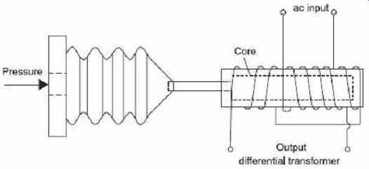
FIG. 18 Pressure measurement with bellows and
LVDT
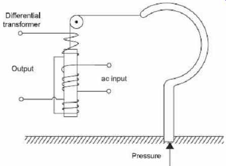
FIG. 19 Pressure measurement with Bourdon tube and LVDT
7.4 Capacitive Transducers
In this type of transducers, a linear characteristics can be achieved by using a differential arrangement for the capacitive displacement transducers. The arrangement using three plates is shown in Figure 20. P 1 and P 2 are fixed plates and M is the movable plate to which the displacement to be measured is applied. Thus, two capacitors are there whose differential output is taken.
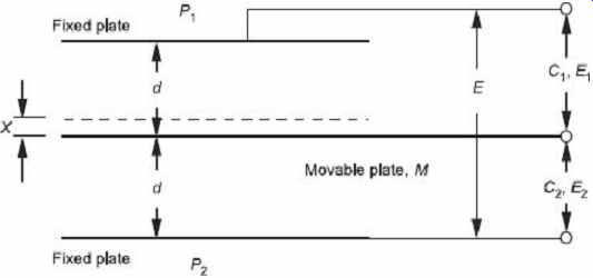
FIG. 20 Differential arrangement of capacitive
transducer
Let the capacitance of these capacitors be C1 and C2 respectively, when the plate M is midway between the two fixed plates, under this condition the capacitances C1 and C2 are equal.
Where ε = Permittivity of the medium between the plates, A = Cross-sectional area of the plates, D = Distance between the plates.
An ac voltage E is applied across plates P1 and P2 and the difference of the voltages across the two capacitances is measured. When the movable plate is midway between the two fixed plates C1 = C2 and therefore E1 = E2 = E/2.
Therefore, differential output when the movable plate is midway ΔE = E1 - E2 = 0 Let the movable plate be moved up due to displacement x , therefore the values C1 and C2 become different resulting in a differential output voltage.
Therefore, the output voltage varies linearly as the displacement x .
The use of a three-terminal variable differential circuit capacitor is shown in Figure 21 . Spherical depressions of a depth of about 0.025 mm are ground into the glass discs.
The depressions are coated with gold to form the two fixed plates of the differential capacitor. A thin stainless steel diaphragm clamped between the discs acts as the movable plate.
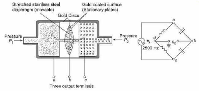
FIG. 21 Capacitive transducer and bridge circuit
When equal pressures are applied (i.e., P 1 = P 2), the diaphragm is in the neutral position and the bridge is balanced. The output voltage e 0, is zero under this condition. If one pressure is made greater than the other, the diaphragm deflects in proportional to the differential pressure, giving an output voltage e0 , from the bridge terminals. This output voltage is proportional to the differential pressure. For an opposite pressure difference, the output voltage shows a 180° phase shift.
The use of capacitive transducers is not common because of low sensitivity. Also capacitive transducers require high carrier frequencies (typically, 2.5 kHz) for dynamic pressure measurement.
7.5 Photoelectric Transducers
The properties of a photoemissive cell or phototube are used in photoelectric transducers.
The vacuum photoelectric cell consists of a curved sheet of thin metal with its concave surface coated with a photoemissive material, which forms the cathode, and the rod anode mounted at the centre of curvature of the cathode. The whole assembly is mounted in an evacuated glass envelope as shown in Figure 21 . The material, coated cathode, emits electrons when light radiation strikes them. The emitted electrons from the cathode are collected by a positive electrode (anode) forming an electric current.
Figure 22 also shows the current versus voltage characteristics of a typical highly evacuated phototube. It is found from the curve that for the voltage above approximately 20V, the output is nearly independent of the applied anode voltage but entirely depends upon the amount of incident light (denoted by its wavelength in Figure 21 ). The current through the phototube produced as a result of incident light is very small. This current is the output of the photo-electric transducers. As the current is in the order of some few μA, it must be amplified to provide a usable output.
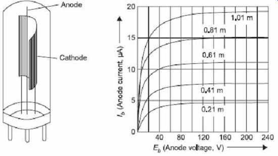
FIG. 22 Photoemissive cell and its voltage vs
current characteristic
The photoelectric transducer uses a phototube and a light source separated by a small window, whose aperture is controlled by the force summing device of the pressure transducer (Figure 23 ). The displacement of the force summing devices modulates quantity of incident light falling on the phototube. Applied pressure or force changes the position of the force summing device which in turn changes the position of the window thus causing a change in incident light. According to curves in Figure 22 a change in light intensity varies the photoemissive property at a rate approximately linear with displacement. These transducers either use a stable source of light or an ac modulated light.
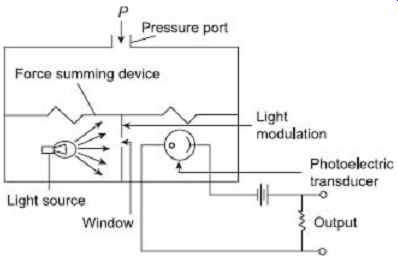
FIG. 23 Pressure measurement using photoelectric
transducer
7.6 Piezoelectric Transducers
When piezoelectric crystals are under the influence of some external force or pressure, they produce an emf. The force or displacement or pressure to be measured is applied to the crystal. The pressure is applied to the crystal through a force summing device. This causes a deformation which produces an emf which is a function of the deformation. This output emf may be measured to know the value of applied force and hence the pressure.
7.7 Ionization Transducers
Ionization is the process of removing an electron from an atom producing a free electron and a positively charged ion. Ionization may be produced by the collision of a high speed electron from the atom. Figure 24 shows the essential features of an ionization-type gauge. Electrons are emitted from heated cathode using a filament and are accelerated towards the grid, which is positively charged. Some of the electrons are captured by the grid, producing grid current I G . Electrons having high kinetic energy pass through and cause ionization of gas atoms.
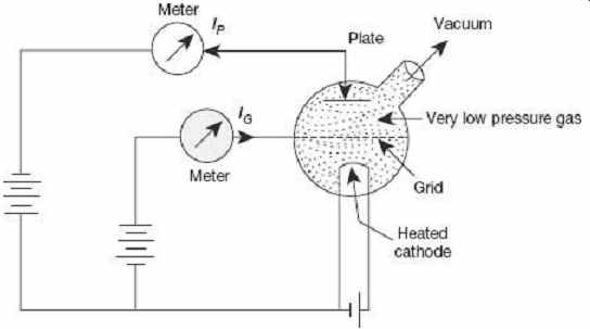
FIG. 24 Ionization type vacuum gauge for measurement of low pressure.
The positive ions so produced are attracted to the plate, which is at negative potential and a current I p is produced in the plate circuit. It is found that the pressure of gas is proportional to ratio of plate to grid current, where S = constant of proportionality S is called the sensitivity of the gauge. A typical value of S for nitrogen is 20 torr-1.
However, the exact value must be determined by calibration of particular gauge since sensitivity S is a function of the geometry of the tube and the gas filled in it. Pressure that can be measured by ionization gauge ranges form 10^-3 to 10^-8 mm of Hg.
7.8 Oscillation Transducers
These types of transducers use a force summing device to change the capacitance, C , or inductance, L , of an LC oscillation circuit. Figure 25 shows the basic elements of LC transistor oscillator whose output frequency is affected by a change in the inductance of a coil. The change in inductance is caused by the force summing device acting upon an inductive device. The output of oscillator is a modulated output and can be demodulated and calibrated in terms of the pressure or force applied.
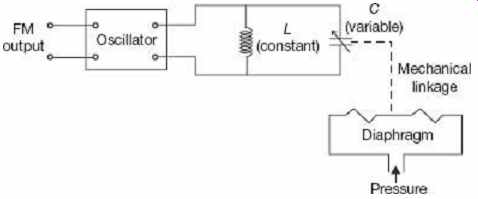
FIG. 25 Basic elements of an oscillation transducer.
EXERCISE
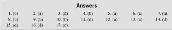
Objective-type Questions
1. Capacitive transducers have the advantages of (a) very high input impedance (b) very high input impedance, excellent frequency response, high sensitivity and not being affected by stay magnetic fields (c) both (a) and (b) (d) none of the above
2. The transducer that converts measurand into the form of pulse is called the ____ transducers.
(a) digital (b) active (c) analog (d) pulse
3. A ____ is commonly used for the measurement of temperature (a) photodiode (b) strain gauge (c) piezo-crystal (d) thermistor
4. LVDT windings are wound on (a) copper (b) ferrite (c) aluminum (d) steel sheets (laminated)
5. The strain gauges should have low (a) resistance temperature coefficient (b) resistance (c) gauge factor (d) all of the above
6. Which of the following devices can measure pressure directly? (a) Bourdon tube (b) Rotometer (c) Both (a) and (b) (d) Neither (a) nor (b)
7. The lower limit of useful working range of a transducer is determined by (a) transducer error and noise (b) minimum useful input level (c) dynamic response (d) cross-sensitivity
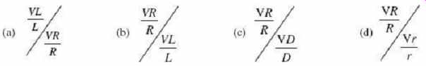
8. Which one of the following gives the gauge factor of a strain gauge?
9. Self-generating type of transducers are:
(a) Inverse (b) active (c) passive (d) secondary
10. The sensitivity factor of strain gauge is normally of the order of (a) 1 to 1.5 (b) 1.5 to 2.0 (c) 0.5 to 1 (d) 5 to 10
11. A pair of active transducers is (a) thermocouple, thermistors (b) thermistors, solar cell (c) solar cell, LVDT (d) thermocouple, solar cell
12. The transducers that convert the input signal into the output signal, which is a continuous function of time, are known as (a) analog (b) digital (c) active (d) passive
13. A strain gauge with a resistance of 250 Ω undergoes a change of 0.150 Ω during a test. The strain is 1.5 × 10^-4 .
Then the gauge factor is (a) 4 (b) 3 (c) 2 (d) 100
14. Consider the following transducers:
1. LVDT
2. Piezoelectric
3. Thermocouple
4. Photovoltaic cell
5. Strain gauge
Which of these are active transducers? (a) 2, 3 and 5 (b) 1, 3 and 4 (c) 1, 2 and 5 (d) 2, 3 and 4
15. LVDT can be used for (a) angular velocity measurement of a column (b) load measurement (c) vibration measurement (d) force measurement in a beam
16. Thermocouples (a) require reference junction compensation (b) are most commonly used as temperature transducer (c) have an ion output voltage level (d) all of the above
17. A thermocouple temperature indicator with reference junction at room temperature has a time constant of 1sec. It is dipped in a hot bath of 120°C. If the room temperature is 20°C, after 1 s the thermocouple type temperature indicator will read (a) 63.2°C (b) 100°C (c) 120°C (d) 140°C
Short-answer Questions
1. What is the definition and importance of primary sensing element? Enlist some of the most commonly used primary sensing elements.
2. Name different elastics pressure elements and give their useful working range and other characteristics.
3. Distinguish between active and passive electrical transducers and give some examples of them.
4. What are the differences between sensors and transducers?
5. Describe a method for measurement of differential pressure.
6. What is an electrical transducer? What are the basic requirements of a transducer? Give the classification of a transducer.
7. Explain how thermistor can be used for temperature measurement.
8. What are the advantages and uses of the LVDT?
9. What are capacitive transducers? What are their advantages and disadvantages?
Long-answer Questions
1. What are thermistors? Explain the working, construction and applications of thermistors. Compare resistance temperature characteristics of a typical thermistor and platinum.
2. Write down the construction and working principle of a thermocouple. Compare different thermocouple materials.
Describe the advantages, disadvantages and applications of thermocouple.
3. What is an LVDT? Explain its working principle with necessary diagrams and characteristics. What are its advantages and uses?
4. Explain the working principle of a linear variable differential transformer (LVDT). Show how it can be used for measuring small mechanical displacements.
5. Describe with suitable diagrams the working principle of strain gauges. Describe the terms Poisson's ratio and gauge factor.
6. With a neat sketch, briefly describe the principle of electromagnetic flow meter. What are the advantages of an electromagnetic flow meter?
7. (a) What are the errors that occur that during the measurement using a thermocouple?
(b) What are the secondary transducers used for pressure measurement? Explain any one them briefly.