AMAZON multi-meters discounts AMAZON oscilloscope discounts
1. INTRODUCTION
Magnetic quantities are measured using a variety of different technologies. Each technique has unique properties that make it more suitable for particular applications. These applications can range from simply sensing the presence or change in the field to the precise measurements of a magnetic field's scalar and vector properties. Magnetic measurements are most difficult to make and essentially less accurate than electrical measurements for two reasons. First, in magnetic measurement, flux is not measured as such, but only some effect produced by it, such as the voltage induced by a change of flux.
As a second and greater difficulty, flux paths are not defined as are electrical circuits- difficulties are definitely faced in precision ac bridges in making the electrical circuits, but the magnetic situation is radically worse and not subject to the same control.
2. TYPES OF MAGNETIC MEASUREMENTS
Magnetic measurements can be divided into two general classes: direct-current (dc) tests and alternating-current (ac) tests. Although quite different methods and objectives are found, these are the two most distinctly defined classes of tests. The dc branch may be further subdivided into measurement of field strength, flux, permeability, B-H curves and hysteresis loops. Such tests are most generally made upon solid materials, the ac test methods being used chiefly for laminated materials. The ac measurements are concerned mainly with losses in magnetic materials under conditions of alternating magnetization.
3. THE BALLISTIC GALVANOMETER
The ballistic galvanometer is used to measure the quantity of electricity passed through it.
This quantity in magnetic measurements is the result of an emf instantaneously induced in a search coil connected to the galvanometer terminals, when the magnetic flux interlinking with the search coil is changed. Such a galvanometer is usually a D'Arsonval type, since this type is least affected by external magnetic fields. It does not show a steady deflection when in use, owing to the transitory nature of the current passing through, but gives a "throw" which is proportional to the quantity of electricity instantaneously passed through it. In the ballistic case the current flow takes place in a short period of time. The coil receives a momentary impulse, which causes it to swing to one side and then return to rest, either gradually or after several oscillations, depending on the damping. The deflection is read at the extreme point of the first throw.
The discharge through the ballistic galvanometer must occur in a short time, that is, before the coil has moved appreciably from its rest position, in order that the throw shall be directly proportional to the quantity of electric discharge. Galvanometers for ballistic use are designed, according to have a longer period than that of ordinary type. The long period is secured by large inertia of the moving system and small restraining torque of the suspension. The inertia has been secured in some galvanometers by the addition of dead weight to the moving system. It is preferable to design the coil for greater width so that the added copper not only increases the inertia but also enhances the sensitivity.
Equations describing the behavior of a ballistic galvanometer may be derived as follows. The torque developed by the coil at any point of time is where L, W and n are respectively, the length, width and number of turns of the coil, and B is the air gap flux density.
The torque of acceleration is where J is the moment of inertia of the coil about its axis and w is the angular velocity.
Now if the coil is close to its zero position during the time the discharge takes place, the torque of the suspension is practically zero, and if the damping torque is negligible in comparison with the driving torque during this time, the value of derived torque may be equal. Therefore, during this short discharge period …
By integrating, we get, where, the subscript zero refers to conditions at the end of the discharge time. The integral form on the right side of Eq. (4) is the quantity of charge that has passed through the coil during this period. Therefore, …
The above expression indicates that the velocity which the coil acquires from the impulse and with which it begins its swing is proportional to the quantity of charge that passed through it. This depends on Eq. (3) , which in turn, is true only if the entire discharge takes place before the coil has moved appreciably from its rest position. This is the reason for the requirement of a long period for the galvanometer swing.
During the actual motion, the deflection toque is zero and the equation of motion is where, D is damping constant, S is the control constant and θ is the deflection in radians.
The solution of this equation is where, A and B are constants and m1 , m2 . Here, the damping is small and as a result, m1 and m2 are imaginary. In the present application, the initial conditions are …
Under this condition, the solution may be written as where, Notice in Eq. (9) that deflections are proportional to ω0 , which from Eq. (5) is proportional to Q . The deflection of the galvanometer may accordingly be used as a measure of quantity of electricity discharged through it.
The amplitude of the first swing θ 1 , for "undamped" case ( D ≈ 0) is from Eq. (9).
The ratio of successive swings with damping present is found by exponential multiplier in Eq. (9) for a time interval such that βt = or t = /β . The ratio of successive swings is …
The natural logarithm of this ratio is referred to as "logarithmic decrement" of the galvanometer and has the value The third swing may be found in the same manner as follows.
In general, In case of critical damping, Eq. (9) will be modified as follows.
Maximum deflection is found for or t = 2 J/D from Eq. (16) . Substitute this value in Eq. (15) and call the deflection θ 1 ; then …
Since, D 2 /4 J 2 = S/J for critical case.
It is interesting to compare Eq. (18) with Eq. (10) . The deflection in the critically damped case is 1/ e or 36.8 % of the undamped deflection, but it is still a direct measure of …
ω0 or Q . The loss of sensitivity is not much serious, since conditions can usually be arranged to give ample deflection.
Summarizing the results of this study in the following equation of the charge passing through the galvanometer, The usual working units in Eq. (19) are ...
K 2 = galvanometer sensitivity in microcoulombs/millimeter deflection ...
θ = deflection in millimeters
Q = charge in microcoulombs In theoretical study, θ was in radians and Q in coulombs, but the units above are ones in common use in laboratory work.
The sensitivity K2 has been shown to depend on the damping. Curves may be found showing the relationship of sensitivity to damping in order to give an idea of the nature of variation. The sensitivity for a set of measurements, however, should be obtained by calibrating conducted under the actual conditions of use.
3.1 Measurement of Magnetic Flux by Ballistic Galvanometer
To sense magnetic flux of a bar magnet, it is surrounded by a search coil or pick-up coil that is connected in series with a variable resistor and a galvanometer. The circuit diagram of this measurement scheme is shown in Figure 1. The series resistor is set to give critical damping and it may also be used to control sensitivity. The sensitivity may be controlled satisfactorily by adjusting the number of turns in the search coil. When the magnet is suddenly withdrawn from the coil, an impulse of short duration is produced in the galvanometer and the first deflection of the galvanometer may be taken as a measure of the flux. The induced voltage in the search coil in the process is where, flux is measured in webers and N is the number of turns in the search coil. If R is the total resistance of the circuit, including search coil, series resistor and galvanometer, the momentary current flowing through the circuit is ...
Neglecting the sign, the quantity of charge passed through the galvanometer is …
Deflection of the galvanometer is …
While performing this test, two points should be noted: first, the change of flux must be made in a short time interval in comparison with the period of the instrument; second, the galvanometer is here used in a closed circuit and hence is subject to electromagnetic damping. The sensitivity factor, K 2 , must be properly evaluated for the resistance used in the test measurements.
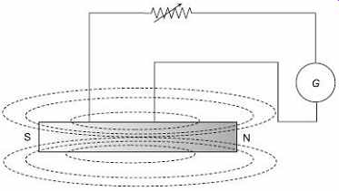
FIG. 1 Measurement of magnetic flux by ballistic
galvanometer
3.2 Calibration of the Ballistic Galvanometer
This may be carried out in a number of ways. Some of the methods are as follows:
1. By Means of a Capacitor
A capacitor which has been charged to a known voltage is discharged through the galvanometer. The circuit diagram of the scheme is shown in Figure 2. The resistor and S2 switch are used to bring the galvanometer to rest quickly after a deflection. The capacitor is charged by the upper position of the S 1 switch and discharged by temporary contact in the lower position. The quantity of electricity discharge can be calculated from the known voltage and capacitance of the capacitor i.e. Q = CE , so the constant K 2 is derived from the charge divided by the observed deflection. This, as described, is the undamped sensitivity, because, the galvanometer circuit has infinite resistance. A shunt may be added, as shown by the dotted line and a new calibration can be obtained. The shunt also gives damping, and if the shunt is much below the critical value, the action is sluggish. Damping conditions may be improved by a combination of shunt and series resistances.
This method is not in general used owing to the difficulty of determining exactly the capacitance of the capacitor under all conditions and also because of the fact that the damping of the galvanometer during calibration is different from that during testing.
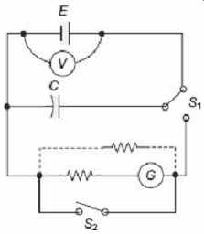
FIG. 2 Calibration of a ballistic galvanometer
by capacitor
2. By Means of a Standard Solenoid
This method is most commonly used for calibration purposes. A standard solenoid consists of a long coil of wire wound on a cylinder of insulating and nonmagnetic material. There may be one or more layers of wire, but the design is such that the axial length of the solenoid is large compared with its mean diameter. Usually, the axial length is at least 1 meter, while the mean diameter is of the order of 10 cm. The winding should be uniform and the number of turns per meter axial length should be such that a field strength, H, of 10,000 A/m or more is obtained at the centre of the coil when carrying its maximum allowable current. This type of dimensions set a practically uniform field near the center.
The test coil or search coil wound closely around (or else placed inside) the middle of the long solenoid as shown in Figure 3 . Here, the calibration is done for flux measurements by means of a known flux, and the calibration and damping remain constant if the same total resistance in the galvanometer circuit is maintained at all times.
The flux linking the search coil is given by where, N 1 = primary turns per meter length of solenoid
I 1 = primary current in amperes
A = cross section area of test coil in square meters, if placed inside = cross section area of solenoid, if test coil is closely wound outside.
Thus, the circuit is operated by throwing the reversing switch from one position to other. As a result, this arrangement creates a flux change twice as great as above, so by substitution in (23) where, N 2 = turns on the test coil.
R = resistance of the test coil and galvanometer circuit…
The sensitivity factor K2 can thus be established from Q and the observed deflection. The calibration for flux measurements may be placed in convenient form, once K 2 is evaluated.
If the galvanometer is used to measure an unknown flux, it may be written …
that where, Φ x = unknown flux change
θ 1x = deflection in millimeters
N x = number of turns used in the search coil
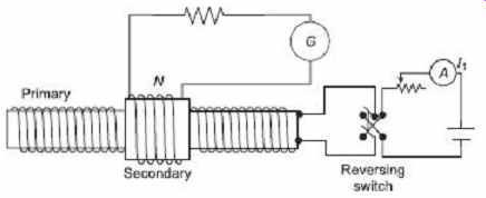
FIG. 3 Calibration of ballistic galvanometer
by solenoid
3. By Means of a Mutual Inductance
The solenoid and search coil provide a calculable mutual inductance, but it is a common practice to use a variable mutual inductor. This procedure has the advantage that a large range of calibration points can be obtained, and the mutual inductor is usually smaller and more convenient than the long solenoid. This test is practically same as the earlier test, but expressed in a somewhat different way. If the mutual inductance between test coil and solenoid is known, following the circuit connection as shown in Figure 4 , a deflection ...
θ 1 produced by the reversal of a known primary current I is observed.
By changing primary current, ...
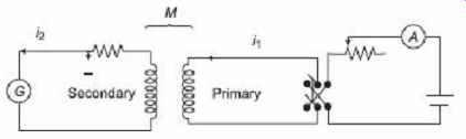
FIG. 4 Calibration of ballistic galvanometer
by mutual inductor
Let R be the total resistance of galvanometer circuit.
Galvanometer current, By integration, So, …
4. FLUXMETER
A fluxmeter is superior over the ballistic galvanometer for some kinds of magnetic measurements. It is a special form of ballistic galvanometer with some modifications, like, the torque of the suspension is made very small, and the electromagnetic damping is very heavy. Apart from portability, it has the advantage that unlike a ballistic galvanometer, the flux change for short time is not necessary. The deflection obtained for a given flux change does not depend on the time taken making the change of flux.
The construction of the meter is shown in Figure 5. The coil is supported by a silk fiber from a spring support. The current connections are made by spirals having the maximum possible spring effect. To make the restoring torque of the system as nearly zero as possible, the suspension and spirals are present in the construction. The search coil and moving coil are of low resistance to get a heavily overdamped moving system during electromagnetic action. The meter coil follows flux changes very rapidly and is practically deadbeat in its action. After being deflected, the coil stays almost stationary and moves extremely slowly toward the zero position; thus, the fluxmeter is much easier to read than a ballistic galvanometer. A mechanical or electrical return arrangement must be used to bring the pointer back to zero. Fluxmeters are usually of portable type, carrying a pointer and scale.
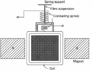
FIG. 5 Construction of a fluxmeter.
The derivation for the ballistic galvanometer was based on the assumption that discharge through the coil takes place before it moves appreciably from the rest position and the damping has a negligible effect during this period. This is not true for a fluxmeter because of the heavy damping action. With a low circuit resistance, a large accelerating torque acts on the meter coil whenever the search-coil voltage exceeds the back voltage caused by the motion of meter coil. As a result, the meter coil responds quickly and is well along in its movement while the flux change is under progress, regardless of whether the flux change is fast or slow. The almost complete absence of a counteracting suspension torque permits the meter to add the effects of a separate flux changes over a short period of time and gives independence of the overall time, within reasonable time.
The voltage generated in the fluxmeter coil by its motion becomes the controlling element in this meter because of the low resistance of the moving system and of the absence of torque from the suspension. The coil voltage could be expressed as the change of the flux linkages, but since the turns and magnet strength are constant it is more convenient for this purpose to relate voltage to coil velocity or where K1 = BLnW is the coil constant.
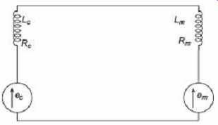
FIG. 6 Analysis of fluxmeter action.
The quantities required in the analysis are shown in the Figure 6. The voltage induced in the search coil is indicated by a small generator marked e g and the back emf caused by the motion of the fluxmeter coil by another generator, e m. In the electrical circuit, Using Eq. (34) in Eq. (35) and solving for i , The equation of coil motion can be written with the term for suspension torque omitted.
The net torque is equated to the amount produced by the current where, J = moment of inertia
D = constant of friction and air damping
Substituting i and after simplifying,
Now, integrating all with respect to time.
where, R = R c + R m
The air-damping effect and the resistance are both small, and accordingly, the first term is nearly equal to K1 . Therefore, ...
Equation (40) indicates an interesting physical fact. The quantity on the right is the change of flux linkage with search coil, and the quantity on the left is the change of flux linkage with the meter coil. If the operator withdraws a magnet from the search coil, reducing the flux linkage with that part of the circuit, the meter coil moves in a direction to restore the flux linkages and thus to keep the total constant for the circuit. The fluxmeter does this within the limits set by the degree to which air damping and suspension torque are negligible.
The effect of shunting the meter by a simplified form as shown in Figure 7 , can be derived. Since induced terms do not appear in the result, at the starting they are dropped in study.
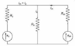
FIG. 7 Simplified circuit for a shunted fluxmeter
According to the above figure, two circuit equations can be written, By substituting for i s in Eq. (41) of its value from Eq. (42), If it is solved for i m from Eq. (43) , substituting the value in Eq. (37) ...
and in the approximate form Comparison of Eq. (40) and Eq. (45) shows that the main effect of the shunt is to apply a shunting factor R s /(R c + R s ) to the reading. The resistance circuit, as shown in the correction term in Eq. (39) or Eq. (44) , is not of extreme importance. However, for accurate work, the total resistance should be brought to the same value used in calibration by the addition of a series resistance if necessary.
5. USES OF BALLISTIC GALVANOMETER AND FLUXMETER
Flux measurements may be done in open or close frame electromagnets when the current in the magnet coil be either switched on and off or reversed. A search coil with suitable number of turns needs to be wound around the magnet. If the flux in the field pole of a large motor or generator is being measured, even a single-turn search coil may give enough deflection, and it will be necessary to shunt the meter. The fluxmeter has the advantage in such measurements that the flux need not to be changed in a short time- changes should be made too rapidly, particularly in large machines.
The flux of a permanent magnet can be measured if the search coil can move on and off the magnet. It should be placed always in the same position with respect to the magnet to get consistent result.
The field strength between magnet poles can be measured if there is room to insert and remove the search coil. Another method, used in fields of considerable extent is a "flip coil", which is a coil mounted so that it can be rotated an exact 180° in a short period of time. The fluxmeter indication can then be interpreted in terms of field strength.
B-H curves of a ring-shaped samples of magnetic material may be obtained by a ballistic galvanometer or fluxmeter in conjunction with search and magnetizing coils would around the sample. Similar tests are run on straight-strip samples by means of "permeameter".
6. MEASUREMENT OF FLUX DENSITY
Measurement of flux density inside a specimen can be done by winding a search coil over the specimen. This search is known as a "B-coil". This search coil is then connected to a ballistic galvanometer or to a fluxmeter. Scheme of measuring the flux density in a ring specimen is shown in Figure 8 . Let, the current I is flowing through magnetizing winding wound around the specimen. A search coil with suitable number of turns is wound around the specimen and connected through a resistance and calibrating coil, to a ballistic galvanometer.
The current through the magnetizing coil is reversed and therefore the flux linkages of the search coil change inducing an emf in it. This emf sends a current through the ballistic galvanometer causing it to deflect.
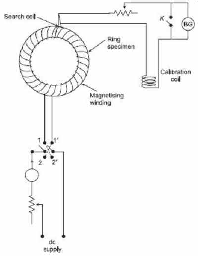
FIG. 8 Circuit to measure flux density of a
ring specimen
φ = flux linking the search coil
R = resistance of the ballistic galvanometer circuit
N = number of turns in the search coil and t = time taken to reverse the flux Average emf induced in the search coil So, average current through the ballistic galvanometer is, Charge passing through it, Let θ 1 be the deflection of the galvanometer. Charge indicated by the galvanometer =
K 2 θ 1
In uniform field and with search coil turns at right angles to the flux density vector, the flux density, …
where, A s = cross-section area of the specimen.
Thus, observing the throw of the ballistic galvanometer, flux density may be measured.
For the above analysis, it is assumed that the flux remains uniform throughout the specimen and that the effective cross-section area of the search coil is equal to the cross-section area of the specimen. However, search coil is usually of larger area than the specimen and thus the flux linking the search coil is the sum of the flux confined in the specimen and the flux which is present in air space between the specimen and the search coil.
So, Flux observed = Actual flux in the specimen + Flux in the air space between specimen and search coil.
or,
B'A S = BA S + μ 0 H(A c - A s ) Hence, actual value of the flux density where, B' = apparent or observed value of the flux density
B = actual or true value of the flux density in the specimen
A s = cross-section area of the specimen
A c = cross-section area of the coil
7. MEASUREMENT OF MAGNETIZING FORCE (H)
A ballistic galvanometer and a search coil may be used to measure the magnetizing force of a constant magnetic field. The value of H inside the specimen may either be obtained from the calculations with data of magnetizing coil and the specimen or from measurements made from outside the specimen. Direct measurement cannot be done. If the magnetizing force is to be determined in the air gap, the search coil is placed in the air gap itself. In case of testing ferromagnetic materials, the magnetizing force, within the specimen may be determined by measuring the magnetizing force on its surface, since the tangential components of the field are of equal in magnitude for both sides of the interface. The search coil, as placed in Figure 9, measures flux density in air, B 0. This search coil is called an "H coil". While the flux densities encountered in iron testing, there is usually no trouble in getting a good sensitivity by using a B -coil of sufficient turns but there is some difficulty in achieving adequate sensitivity in the H coil placed at the surface. At the first instance, its cross-sectional area is much smaller than the coil surrounding the specimen and then H is not constant across the section. Secondly, the permeability of iron is very large as compared to that of air and therefore flux density B 0, in the search coil, is very small compared to that in the specimen. The value of the flux density B 0 in H coil is measured in a similar way as described before for measuring of B in …
…a specimen.
Magnetizing force, H = B 0 /μ 0
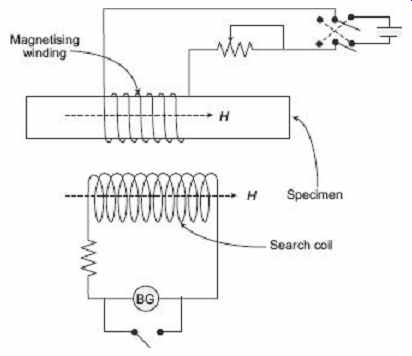
FIG. 9 Circuit diagram to measure magnetizing
force
Testing Ring and Bar Specimens
The ballistic methods which are done on ring specimens give highest accuracy provided the test conditions are controlled properly. The main advantage of ring specimens is that the end effects are absent in ring specimens and test errors due to magnetic leakage are not encountered.
To avoid magnetic leakage, a uniform distribution of mmf is maintained by a uniformly wound magnetizing winding on the ring sample. The magnetizing force is usually calculated in terms of mean diameter of the ring and the mmf in the magnetizing winding.
Since, the inner periphery of ring specimen is smaller than the outer periphery, the magnetizing force and the flux density become nonuniform over the cross-section of the ring. The error involved depends upon the ratio of mean diameter to the radial width of the ring. But, when this ratio is more, both magnetizing force and the flux density are sufficiently uniform over the cross-section of the specimen and as a result, the error involved in test result is not significant.
The ring specimens may take on of the following shapes:
1. Laminates
It is the common form for isotropic sheet material. The ring is assembled with the direction of rolling of individual laminations distributed radially, in order that the test should exhibit results corresponding to mean properties of the material.
2. Clock-spring
A long strip of material may be wound in the form of spiral to form a ring. This form is suitable for testing anisotropic materials, i.e., grain-oriented steel.
3. Solid
Solid rings are prepared by either casting or forging. Ring specimens are also used for testing powder or dust core material.
The ring is prepared for the test by first winding on it a thin layer of insulating tape and then a search coil of a suitable number of turns, evenly distributed around the ring.
Insulating tape is applied over the search coil, and then the magnetizing coil is wound on the ring. The magnetizing coil should be spaced uniformly around the ring and must consist of a suitable number of turns of wire of adequate current-carrying capacity to give the number of ampere-turns required for the tests.
8. DETERMINATION OF MAGNETIZING CURVE
There are two methods used to determine the magnetizing curve or B-H curve of a specimen.
1. Method of Reversal
A ring specimen with known dimensions is used for the test. At first, ring specimen is prepared by placing search coil, and magnetizing coil with proper insulation arrangement as mentioned earlier. The arrangement of the test circuit is shown in Figure 8 .
After demagnetizing the test is started by setting the magnetizing current to its lowest test level. At that time, the galvanometer switch is closed, the iron specimen is brought into a reproducible cyclic magnetic state by throwing the reversing switch S backward and forward about twenty times. The K switch is now opened and the value of flux corresponding of this value of H is measured by reversing the switch S and recording the throw of galvanometer. The value of flux density corresponding to this H can be calculated by dividing the flux by the cross-section area of the specimen. This procedure is repeated for various values of H to maximum testing point. The B-H curve may be plotted from the measurement values of B corresponding to the various values of H .
2. Step-by-step Method
For this test, the circuit diagram is shown in Figure 10 . In this test the magnetization winding of the ring specimen is supplied from a potential divider having few tappings.
The tappings are arranged so that the magnetization force H may be increased in suitable number of steps, up to desired maximum value. Before testing the specimen, it must be demagnetized.
Keeping the switch S 2 on the tap 1 position, the switch S 1 is closed. Current flow in the magnetizing winding sets up a magnetizing force, H 1 which in turns increases the flux density in the specimen, from zero to some value B 1 , and corresponding throw of galvanometer is observed. The B 1 value can be calculated from the throw of the galvanometer. H 1 value may be calculated from the reading of the ammeter, connected to the magnetizing winding circuit. The magnetizing force is then increased to some value H 2...
…by switching S 2 suddenly to the tapping 2 and the corresponding increase in flux density ΔB is determined from the throw of the galvanometer. Then the flux density B 2 corresponding to magnetizing force H 2 is calculated as B 2 = B 1 + ΔB . The process is repeated for other values of H up to the maximum point and the complete B-H curve thus drawn as shown in Figure 11 .
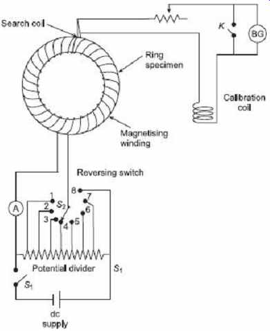
FIG. 10 Circuit to measure magnetizing curve
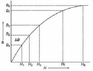
FIG. 11 Magnetizing curve