AMAZON multi-meters discounts AMAZON oscilloscope discounts
(cont. from part 1)
9. DETERMINATION OF HYSTERESIS LOOP
1. Step-by-step Method
The determination of the hysteresis loop by this method is carried out simply by continuing the procedure described in the previous section where the B-H curve was obtained. After reaching the point of maximum H with S 2 on the tapping 8, the magnetizing current is then reduced, in steps to zero by moving S 2 down through tapping points 8,7,6…2,1. After the reduction of the magnetizing force to zero, negative values of H are obtained by reversing the reversing supply to the potential divider and then moving the switch S2 in steps as before.
2. By Method of Reversal
The circuit connections for the test are shown in Figure 12. This test is carried out by means of a number of steps. The flux density is changed in steps from the maximum value + B max down to some lower value, the iron specimen being passed through the reminder of the magnetization cycle back to the flux density + B max . In Figure 12 , R1 is there to adjust galvanometer circuit; whereas, R2 and R4 are there to adjust the magnetizing circuit.
R3 is a variable shunting resistor, connected across the magnetizing winding by moving over the switch S2 , thus reducing the current in this circuit from its maximum value down to any desired value-depending upon the value of R 3 .
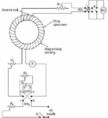
FIG. 12 Circuit to measure hysteresis loop
The value of H max required to develop B max to be used during the test is taken from the previously obtained B-H curve of the specimen. R 2 and R 4 are then varied so that the magnetizing current is such that this value of H is obtained when S 2 is in the OFF position.
Since H = NI/l. When the maximum value of the magnetizing is reversed, to get a suitable deflection of the galvanometer, R 1 is adjusted. R 3 is adjusted to such a value that a suitable reduction of the current in the magnetizing winding is obtained when this resistance is switched in the circuit. Switch RS 2 is then placed on contacts 1 1' and the short-circuiting key K opened. Since at this moment, maximum magnetizing current is flowing, the magnetization of the specimen corresponds to the point A on the loop shown in Figure 13 .
In the next step, the switch S 2 is quickly thrown over from the OFF position to contact…
X , thus shunting the magnetizing winding by R 3 and reducing the magnetizing force to…
Hc (say). The corresponding reduction in flux density, −ΔB , is obtained from the galvanometer throw, and hence the point C on the loop is obtained. The key K is now closed, and the switch RS 2 reversed on to contacts 2 2'. Switch S 2 is then opened and RS 2 moved back again to contacts 1 1'. In this procedure, the specimen undergoes a cycle of magnetization and back to the point A and it is ready for the next step in the test. The section AD of the loop is found by continuation of this procedure.
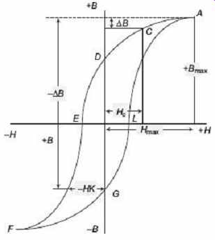
FIG. 13 Hysteresis loop
To find out DEF section of the loop, with K closed and S 2 in the OFF position, RS 2 is placed on contacts 1 1'. Then throw S 2 on the contact Y position, open the key K and rapidly reverse RS 2 on to contacts 2 2'. From this throw, the change in flux ΔB' ( Figure 13 ) may be obtained, since the switching operations described cause H to be changed from + H max to -Hk (say). To bring the magnetization of the specimen back to the point A , close the key K , open S 2 and reverse RS 2 on to contacts 1 1'. By continuing this process, other points on the section DEF of the loop are found. The section FGLA of the loop may be obtained by drawing in reverse of ADEF, since the two halves are identical. By measuring the area of the hysteresis loop so obtained, by means of a planimeter, and expressing this area in B-H units of area, the hysteresis loss for the material may be obtained, since, hysteresis loss/cycle/m 3 in joules = area of the loop in B-H units.
10. TESTING OF SPECIMENS IN THE FORM OF RODS OR BARS
It is obviously much easier to prepare a specimen in the form of a rod or bar than to prepare a ring specimen. However, if test methods described for ring specimens are employed to bar specimens, some difficulties and inaccuracies arise in testing. Bar specimens suffer from the disadvantage of "self-demagnetization". When a bar is magnetized electromagnetically, poles are produced at the ends, and these poles produce, inside the rod, a magnetizing force from the north pole to the south which is in opposition to the applied magnetizing force, thus rendering the true value of H acting on the bar a somewhat uncertain quantity. For accurate results, therefore, if the methods of measurement using a ballistic galvanometer are used, this demagnetizing effect must be corrected for, or, since the effect is least when the ratio of diameter to length of the rod is small, the dimensions of the specimen should be chosen so that the effect is negligible.
The demagnetizing force due to this "end effect" is given by the expression where, B f is the ferric induction, i.e. the flux density due to the magnetization of the iron piece itself, and F is a constant which depends upon the relative dimension of the rod. For an ellipsoid or very long rod, the value of the coefficient F can be calculated from the expression where,
a = minor axis of the ellipsoid
b = major axis of the ellipsoid
To obtain the true value of the magnetizing force H acting on the bar specimen, H d must be subtracted from the value of H calculated from the ampere-turns per meter length of the magnetizing winding. It has been seen that the length-to-diameter ratio of the specimen must be of the order of 25 or more for to have a negligible influence upon the value of H .
On account of this demagnetizing effect, the value of H is often measured by means of search coils wound on thin strips of glass and placed with the glass lying flat on the bar specimen. The flux density in the air at the surface of the specimen (which is same as H in the specimen) is measured by this means instead of relying upon calculated values and corrections.
11. PERMEAMETERS
There are various forms of "permeameters" that have been devised to avoid difficulties incurred to test straight specimens. Permeameters provide controllable field conditions to test bar specimens. They consist generally of a fixed steel frame to which straight samples can be fitted, but differ widely in the arrangement of magnetizing and pick-up or search coils and in the means of guarding against leakage fluxes and mmf drops at the joints. All permeameters use return paths of large cross-section area in order to make the reluctance of the paths negligible. Most of the permeameters incorporate modifications of the bar and yoke arrangements first described by Hopkinson. The following discussion shall be limited only on a few of many forms of permeameters.
11.1 Hopkinson Permeameter ( Bar-and-Yoke Method)
This method is used for the testing of bar specimens and the demagnetizing effect is largely eliminated by the use of heavy-section yokes. A search coil is wound around the bar specimen at its centre, and the bar is then clamped between the two halves of a massive iron yoke, whose reluctance is small compared with that of the specimen, as shown in Figure 14 . The magnetizing winding is fixed inside the yoke, as shown, the specimen fitting inside it.
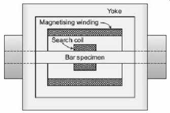
FIG. 14 Bar and yoke method
Let, N = number of turns of the magnetizing winding
I = current in the magnetizing winding
l = length of specimen between two halves of the yoke
A = cross-section of the specimen
μ s = μ sr μ 0 = permeability of the specimen when the magnetizing current is I, μ sr being the relative permeability of the specimen
R y = reluctance of the yoke
Rj = reluctance of the two joints between bar specimen and yoke
Φ = flux in the magnetic circuit
Then, Reluctance of the specimen, R s = l/ μ s A So, flux Φ = mmf/reluctance of magnetic circuit
Flux density in the specimen, Magnetizing force, Let, m = Reluctance of yoke and joints/Reluctance of the specimen The value of m is made small by keeping the reluctance of the yoke and the joints to a small value. This can be achieved by carefully fitting the specimen into the yoke so that air gap between the bar and yoke is negligible and making the yoke of large cross-section.
So if m is small, which means that the actual value of H in the specimen differs from the value calculated from the magnetizing ampere-turns and length of specimen by the amount mNI/l. The flux density may be measured by a ballistic galvanometer in the usual way.
11.2 Ewing Double Bar Permeameter
In this permeameter, two exactly similar bar specimens of the material under test are used, with two pairs of magnetizing coils, one pair of the latter being exactly half the length of the other pair. The number of turns, per unit axial length, is same for both pairs of coil.
Two yokes of annealed soft iron, with holes to receive the ends of the bar specimens-the fit being tight-are used. The arrangement of the bar and yoke is shown in Figure 15.
The purpose of the arrangement is the elimination of the reluctance of yoke and joints.
The tests are done, one with length of specimen = l and the other with length = I /2. It is assumed that for both positions, the reluctance of the yokes and joints is same for a given flux density.
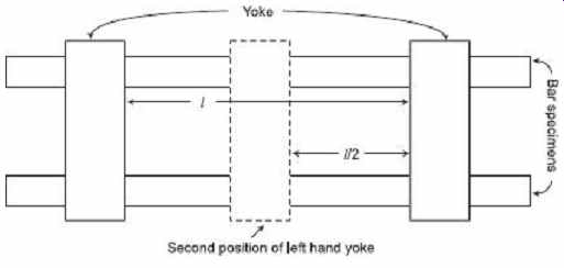
FIG. 15 Ewing double bar method
Let, n = number of turns per unit length of magnetizing coils
I1 = current in the coils when the specimen length is l
I2 = current in the coils when the specimen length is l/2
H1 = apparent magnetizing force when length is l
H2 = apparent magnetizing force when length is l/2
a = mmf required for the yokes and air gaps in each case
B = flux density in the specimen (the same in each case)
Then and If H be the true magnetizing force in the iron for a flux density B ,
Hl = nI 1 l − a = H 1 l − a
and Hl/ 2 = nI 2 l . 2 − a = H 2 l/2 - a
Hence, a = l ( H 2 - H 2 )
And…
The flux density corresponding to this actual value of H is measured by means of search coils and ballistic galvanometer in ordinary way. The complete test is performed by first obtaining and plotting a B-H curve for the specimen with a length of l -the apparent values of H being plotted. The specimens are then demagnetized, and a second B-H curve is obtained, and plotted, with a specimen length of l/2, the two curves being plotted on the same axis. The true B-H curve is obtained from these two, the true value of H , corresponding to any value of B , being obtained from the expression derived above.
The disadvantaged of this method are:
1. the reluctance of the yokes and joints is not exactly same for the two positions of the yoke,
2. the test requires two exactly similar bars, and
3. this test is somewhat lengthy.
11.3 Illiovici Permeameter
As shown in Figure 16 , it consists of a bar specimen clamped against a heavy yoke.
The bar is wound with a magnetizing winding and a search coil. A ballistic galvanometer
BG 1 is connected across the search coil. A magnetic potentiometer is connected to a section XY of the bar specimen. The yoke is provided with compensating winding. It is connected in parallel with the magnetizing winding across a reversing switch. When no magnetic potential drop is indicated by the magnetic potentiometer, the mmf of XY section is provided by the magnetizing winding while for the remaining part of the specimen, the yoke and the joints, is provided by the compensating winding. This condition is achieved by adjusting the current in the main winding to the required test value and then adjusting the current in the compensating winding so that the ballistic galvanometer BG 2 shows no throw when the currents are reversed. Under this condition, there is a no-flux through the magnetic potentiometer and, therefore, no difference of magnetic potential exists between points X and Y. Thus, the magnetizing force for length XY is given by H = NI/l, where, N is the number of turns in the magnetizing winding, I is the current in the magnetizing winding and l is length of XY .
The flux density in the specimen is found by noting the throw of BG 1 when the currents in magnetizing winding and compensating winding are reversed simultaneously. The permeameter has the following disadvantages:
1. Since, there is lack of symmetry in the arrangement, the results obtained are not satisfactory.
2. This arrangement does not include a direct test of uniformity of magnetization along the specimen.
3. Since compensating winding needs to be adjusted for each reading, the overall operation becomes complicated.
4. Some leakage between the yoke and specimen and the magnetic potentiometer may be affected by leakage flux which can introduce error in the test results.
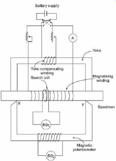
FIG. 16 Illiovici permeameter
11.4 Burrows Permeameter
This permeameter, which was first developed by CW Burrows, has been adopted as the standard apparatus for the testing of bar specimens. The effect of magnetic leakage at the joints between the yoke and specimen is eliminated in this pemeameter by the use of a number of compensating windings which apply compensating mmfs at different parts of the magnetic circuit, these mmfs being just sufficient to drive the flux through the reluctance of the part upon which the coils are placed.
Figure 17 shows the arrangement of the magnetic circuit and coils. S 1 is the bar specimen under test and S 2 is a bar of identical dimensions to S 1 . These bars are surrounded by magnetizing coils M1 and M2 . Magnetizing windings are uniformly wound along the length of the bars. C1 , C2 , C3 and C4 are compensating coils for eliminating the leakage effects at the joints between the two bars and the massive yokes YY' into which the bars fit; cx and cy are two exactly similar search coils wound at the centers of the two bars, while d1 and d2 are two similar search coils wound in the positions shown, on the test bar, and each having exactly half the number of turns of the search coil cx. Coils d1 and d2 are connected in series. Four coils C 1 , C2 , C3 and C4 are also in series. The dimensions of the coils M1 and M2 are such that H in the specimen is around 10 4 times the current in the windings, the maximum value of H for which the apparatus is used being about 40,000 A/m. The dimensions of the bars are around 30 cm long and 1 cm in diameter. The coils C1 , C2 , C3 and C4 are supplied from a separate battery source, coil M1 from another battery and M2 from another. To perform the test, it is necessary, to ensure that for a given value of the current in M1 , i.e. of H in the test bar, the flux threading through all four search coils cx , cy, d1 and d2 is the same, the current in the compensating coils, and in M2 , being adjusted until this condition is satisfied. If the flux threading coils d1 and d2 is the same as that of the threadings cx and cy, there can be no appreciable leakage of flux through the air in the joints. This means that the mmf for the joints is supplied by the compensating coils and that the mmf in coil M1 is used up merely in driving the flux through the bar specimen S1 inside it. Thus, H in the specimen is given by NI/l, where, N is the number of turns on M1 , and I is current through M1 and l is the length of the specimen in meters.
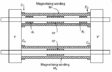
FIG. 17 Magnetic circuit of Burrows double-bar
and yoke permeameter.
It may in some cases, be necessary to make corrections for the fact that the magnetizing solenoids are not infinitely long, but such corrections are usually negligible. The procedure for getting equal flux threading in all four search coils is as follows.
As shown in Figure 18, first, the specimen having been demagnetized, the current through the magnetizing coil M1 is set at the required testing level. Search coils cx and cy are then connected in series, but in opposition, to a ballistic galvanometer, The currents in M1 and M2 are then simultaneously reversed. A throw will be observed on the galvanometer. The current in M2 is adjusted until no throw is obtained when two currents are reversed. Since search coils cx and cy have equal number of turns, this means that equal fluxes are now threading through them. Next, the search coil cx is connected in series with, but in opposition to, coils d1 and d2 and then to the ballistic galvanometer. The current in compensating coils C1 , C2 , C3 and C4 is then adjusted until no galvanometer deflection is obtained upon simultaneous reversal of the currents in these coils and in M1 and M2 . Then, since d1 and d 2 together have the same number of turns as the coil cx , the flux threading all three coils is same. The flux density corresponding to the value of H in M 1 can be measured by connecting the coil cx alone to the ballistic galvanometer, and recording the throw when the currents in the two magnetizing coils and compensating coils are simultaneously reversed. Figure 18 gives a diagram of connection showing how the switching may be arranged for convenience in carrying out the test as described above.
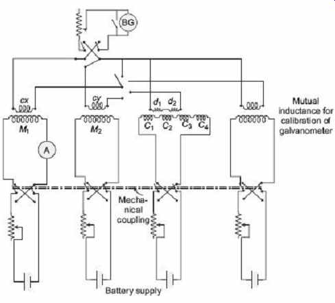
FIG. 18 Circuit for Burrows double bar and yoke
permeameter
12. MEASUREMENT OF MAGNETIC LEAKAGE
In dynamo-electric machinery, the magnetic flux per pole which crosses the air gap-the "useful flux"-is less than the flux in the body of the pole. This is due to the fact that some lines of force, called leakage flux, pass from the pole to the adjacent poles without crossing the air gap to the armature. The flux at the root of the pole is called total flux and the ratio of total flux to useful flux is the leakage factor of the pole.
Leakage factor can be measured by means of a fluxmeter. Here, galvanometer is not suitable on account of the high inductance of the field winding, which results in a slow rate of increase of flux when the voltage is switched on to the field winding. The total flux may be measured by winding two search coils on the yoke of the machine-in case of a dc machine with stationary field-one on either side of the pole as shown in Figure 19 . As the yoke carries half of the total flux, these search coils must be connected in series so that the fluxmeter measure the flux embraced by both of them. The flux so measured will be the total flux. Another search coil, placed on the stationary armature in such a position that it embraces the useful flux from the pole, is then connected to the fluxmeter and the useful flux is measured. The leakage factor is obtained from these two measurements. It will usually be found that search coils of one turn will be most suitable, in which case the fluxmeter reading gives the flux directly.
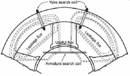
FIG. 19 Measurement of magnetic leakage factor
13. MAGNETIC TESTING WITH ALTERNATING CURRENT
When iron is subjected to an alternating magnetic field, a power loss takes place due to hysteresis effects in the iron. Eddy currents which are set up in the iron further increase the power loss in the material. Although the hysteresis loss per cycle in iron may be determined from hysteresis loop obtained in dc tests, this loss may be somewhat different under the actual alternating magnetization condition with which it will be working. Also, eddy current losses can only be measured by the use of alternating field. For these reasons, inspection tests upon sheet steel which is to be used in the manufacturing process of a transformer and other ac apparatus are very common ac tests. It is usually convenient to measure the hysteresis and eddy current loss in combined form, called iron loss.
Separation of Iron Losses
It is often sufficient, in acceptance tests of sheet material, to measure the total loss at the standard frequency and with maximum flux density of about 1 weber per square meter as the separation of the losses into their two components involves a rather more lengthy test.
Hysteresis loss can be expressed as ...
Wh = k . f . B 1.6 max
where, W h is the loss in watts per cubic meter of material, f being the supply frequency, …
B max the maximum flux density, and k a constant for any given material. This law holds good for values of B max between 0.1 and 1.2 Wb/m^2 .
Eddy current loss, provided the sheets are sufficiently thin for skin effect to be negligible, is given by the expression
W e = k'K f
2 f 2 t 2 B 1.6 max
where, W e is the loss in watts per cubic meter, f is the frequency, t is the thickness of the sheet, and B max is the maximum flux density, and Kf is the form factor of the alternating flux and depends upon the shape of the wave.
Thus, if the form factor remains constant throughout the test and the maximum flux density is kept constant, the total power loss being measured at different frequencies, may be written as…
W t = Mf + Nf 2
where, M = KB 1.6 max
and N = k' Kf 2 1 2 B 2 max
…both M and N being constant for this test.
These constants may be determined, and the total loss thus split up into its two components, for any frequency, by plotting W/f against f is shown in Figure 20 . Then , so that the intercept on the vertical axis gives M , and N can be obtained from the slope of the graph. M is the hysteresis loss per cycle and the eddy-current loss for any frequency f x is given by the intercept ED, as shown in Figure 21 . Again, if the frequency and B max are kept constant and form factor is varied, the total loss being measured for various values of form factors is then
W t = C + DK f 2
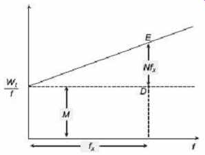
FIG. 20 Separation of iron losses
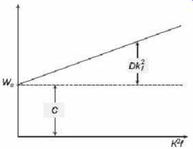
FIG. 21 Separation of iron losses
If W t is now plotted along the y-axis against the values of K f 2 along the x-axis, the constants C and D may be obtained. The intercept upon the vertical axis gives C , and the slope of the line gives D.
14. BRIDGE AND ac POTENTIOMETER METHODS
The ac bridge or ac potentiometer methods are suitable for materials working at low flux densities. A number of bridge circuits are used where materials work at low flux densities and a small quantity of material is available. The test is to be performed at audio frequencies.
14.1 Maxwell's Bridge Method
Figure 22 shows the circuit diagram of the Maxwell bridge which is used to measure iron loss and permeability. R1 , R2 are fixed valued resistors and R3 is a variable resistor. In series with R3 a variable inductor L of resistance r is connected. It may be necessary to connect R3 in series with the winding on the sample if resistance of the latter is small. The specimen, in ring form, is wound with a winding whose inductance is L s and effective resistance R s . This effective resistance contains an iron loss component. Rw is the actual resistance of the winding on the ring. G is a vibration galvanometer or telephone, and an ammeter. This supply from an ac source should be having a pure sinusoidal waveform.
The balance of the bridge is obtained by adjusting L and R 3 .
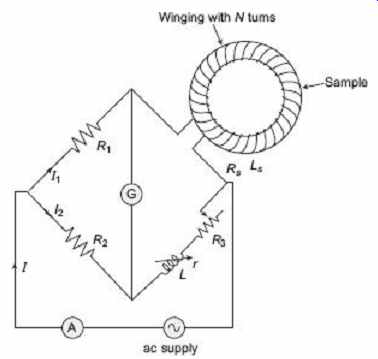
FIG. 22 ac bridge for iron loss measurement.
At balance, ...
I 1 R 1 = I 2 R 2
and I 1 ( R s + jωL s = I 2 [( r + R 3 ) + jωL ]
where, ω=2 × Frequency
The iron loss in the sample is given by
R s I 1 2 − R w I 1 2
Now, the current, I = I 1 + I 2
Here, I 1 and I 2 are in phase.
If N = number of turns on the specimen
l = length of mean circumference of the specimen (in meters)
a = cross section of specimen in square meters
μ r = relative permeability of the specimen
Then the inductance is...
From which, μ r can be calculated when L s has been measured.
14.2 The ac Potentiometer Method
The circuit connection for measurement of iron loss with a potentiometer is shown in Figure 23. The used potentiometer is of co-ordinate type. Here, the ring specimen carries two windings, the primary winding with N1 turns and the secondary with N2 turns, The primary winding is supplied from an alternator through a regulating transformer. The alternator is also supplying to two potentiometer slide-wire circuits. The primary winding circuit contains a regulating resistor and a standard resistor R is connected in series with it.
This resistor is introduced in the circuit to sense the current in the primary winding by measuring the potential drop across it. A vibration galvanometer G is used in the test. At first, the potentiometer is standardized. The supply is fed to the primary winding of the specimen, as a result, the voltage E2 is induced in the secondary winding.
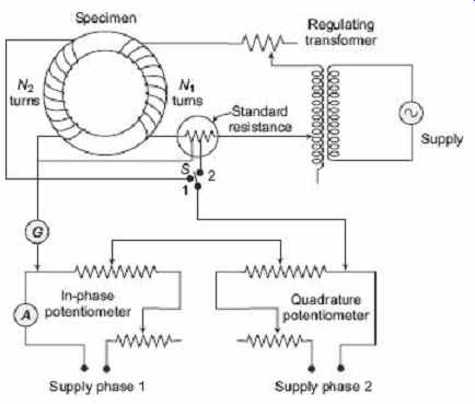
FIG. 23 Iron loss measurement by ac potentiometer.
…where, E 2 = 4 K f f Φ max N2 = 4 K f fB max A s N 2
In the above expression, K f = Form factor = 1.11 for sinusoidal supply, f = Supply frequency, B max = maximum flux density, A s = Cross-section area of the specimen, N 2 =
Number of turns in the secondary winding.
And maximum flux density, The voltage E 2 is measured by placing the switch S on the contact x, setting the quadrature potentiometer at zero and adjusting the in-phase potentiometer till balance is obtained. The setting of the in-phase potentiometer indicates the value of E 2 directly.
The switch is then placed to contact y. At this position, the potential drop in the standard resistor R is matched against the in-phase and quadrature potentiometers. These two potentiometers are adjusted to achieve the balanced condition. The reading of the in-phase potentiometer gives the value I e R where I e is the loss component of the current in the primary winding:
I e = reading of in-phase potentiometer/ R
The reading of the quadrature potentiometer indicates the value of I m R, where, I m is the magnetizing component of the current in the primary winding.
I m = reading of quadrature potentiometer/ R
The iron loss = I e E 2 N 1 /N 2
This method is suitable for ac magnetic testing at low flux densities, since magnetizing and iron-loss components of exciting current are measured separately
15. MAGNETIC SHIELDING
Magnetic shielding is an important issue to prevent magnetic field from interfering with electrical devices. Magnetic shielding is a process of reducing the coupling of a magnetic field between two locations. A number of materials are used for this purpose including sheet metal, metal mesh, ionized gas, or plasma. Unlike electricity, magnetic fields cannot be blocked or insulated. As a result, magnetic shielding is very much essential to stop malfunctioning of electrical and electronics devices and equipments if they are put in service in such an environment where a chance of magnetic interference is prevailing.
According to Maxwell's equations, del. B = 0, which means that there are no magnetic monopoles. As a result, magnetic field lines must terminate on the opposite pole. There is no way to block these field lines; nature finds a path to return the magnetic field lines back to an opposite pole. Even if a nonmagnetic object-for example, glass-is placed between two opposite poles of a magnet, the magnetic field will not change.
The main concept of magnetic shielding is to re-route the magnetic field lines around the object or device under threat of magnetic interference. This can be achieved by surrounding the device with a magnetic material with higher permeability that that of the device inside under threat. By doing so, the magnetic field lines tend to find an easier path along the shielding material, thus avoiding the object inside. This technique merely redirects the magnetic field lines to a material having high permeability, instead of stopping or blocking magnetic field lines.
It is important that materials used in magnetic shielding purpose should have high permeability, but it is also important that they themselves should not develop permanent magnetization. Keeping these points in consideration, the most effective magnetic shielding material available is mu-metal, an alloy containing 77% nickel, 16% iron, 5% copper, and 2% chromium, which is then annealed in a hydrogen atmosphere to increase its permeability. Mu-metal is extremely expensive, that's why other alloys with similar compositions are sold for magnetic shielding, usually in rolls of foil.
Important Areas for Magnetic Shielding
Magnetic shielding is essentially employed in hospitals, where devices such as Magnetic Resonance Imaging (MRI) equipment generate powerful magnetic flux which can interfere with surrounding instruments or meters.
Magnetic shielding rooms are also used in electron beam exposure rooms where semiconductors are made, or in research facilities using magnetic flux.
Applications of magnetic shielding are common in home theatre systems. Speaker magnets can distort a Cathode Ray Tube (CRT) television picture when placed close to the set, so speakers intended for that purpose use magnetic shielding.
Magnetic shielding is also used to counter similar distortion on computer monitors.
Magnetic shielding is quiet essential in laboratories and factories where high-voltage tests or operations are performed. Normally, shielding nets are preferred for this purpose.
EXERCISE
Objective-type Questions
1. Which of the following measures the magnetic flux density? (a) Ballistic galvanometer (b) Grassot fluxmeter (c) Permeameter (d) All of the above
2. When a magnetic material is subjected to alternating field, loss of power occurs owing to (a) hysteresis only (b) eddy current only (c) both hysteresis and eddy currents (d) none of the above
3. The area of the hysteresis loop in magnetic specimen indicates (a) hysteresis and eddy current loss (b) hysteresis loss (c) hysteresis loss per unit volume (d) hysteresis loss per unit volume per cycle of frequency
4. The ratio of total flux to the useful flux in a magnetic circuit is called (a) form factor (b) leakage factor (c) utility factor (d) dispersion factor
5. Maxwell's bridge method is used to measure (a) iron loss and permeability (b) copper loss (c) copper loss and iron loss (d) none of these
Short-answer Questions
1. Why are magnetic measurements not as accurate as other types of measurements in electrical engineering?
2. Why are ring specimens preferred over rods or bars for magnetic testing?
3. Why is the fluxmeter employed to measure leakage factor in electric machinery rather than ballistic galvanometer?
4. What are the components of power loss that occur in ferromagnetic materials when subjected to alternating magnetic fields?
5. What are the methods used for measuring iron losses?
Long-answer Questions
1. What are the different types of magnetic measurement? How is ballistic galvanometer used in magnetic measurement? Explain the working principle of a ballistic galvanometer.
2. Explain how a ballistic galvanometer is used to measure flux changes occurring in magnetic circuits and indicate the essential conditions to be satisfied by the ballistic galvanometer chosen for this purpose.
3. How is the magnetic flux measured by a ballistic galvanometer? What are the different methods to calibrate a ballistic galvanometer?
4. What are ballistic tests used for testing of magnetic materials? How is flux density determined in the ring type specimen of magnetic material?
5. Explain the working principle of a fluxmeter with the help of a neat diagram.
6. Give the advantages and disadvantages of ring and bar specimens used in magnetic testing of materials.
7. Briefly describe a method for measurement of B-H curve of a magnetic substance of bar form.
8. With the help of a circuit diagram, describe the step-by-step procedure to draw the complete B-H loop of a ring specimen.
9. Describe the procedure to determine hysteresis loop by the method of reversal, and suggest precautions to be followed.
10. Discuss the principle and advantage of a permeameter for the determination of B-H curve of a sample.
11. How is the bar-and-yoke method employed to measure the magnetizing force of a specimen?
12. Describe the construction and working of a Burrows permeameter bringing its relative advantages over other types for testing a bar specimen.
13. What are iron losses? How do they vary with frequency? Explain the procedure for separation of iron losses.
14. Explain the ac potentiometer method of determination of iron losses.
15. Write short notes on the following:
(a) Flux measurement (b) Ewing double bar permeameter (c) Illiovici permeameter
(d) Maxwell's bridge method for iron loss measurement