AMAZON multi-meters discounts AMAZON oscilloscope discounts
1. INTRODUCTION
Signal generators provide a variety of waveforms for testing of electronic circuits at low power levels. There are various types of signal generators, but the following characteristics are common to all types:
1. Always a stable generator with desired frequency signals should be generated.
2. Generated signal amplitude should be regulated over a wide range from very small to relatively large level.
3. Generated signal should be free from any distortions.
There are many variations of the above requirements, especially for specialized signal generators such as function generators, pulse generators and pulse frequency generators.
Sine wave generators, both in audio and radio frequency ranges are called oscillators.
Although, the terminology is not universal, the term oscillator is generally used for an instrument that provides only a sinusoidal output signal. The term function generator is applied to an instrument that provides several output waveforms, including sine wave, square wave, triangular wave and pulse trains as well as amplitude modulation of the output signal.
2. OSCILLATORS
Oscillator is the basic element of ac signal sources and generates sinusoidal signals of known frequency and amplitude. The main applications of oscillators are as sinusoidal waveform sources in electronic measurement work. Oscillators can generate a wide range of frequencies (few Hz to many GHz) as per the requirement of the application. Although an oscillator can be considered as generating sinusoidal signal, it is to be noted that it merely acts as an energy converter. It converts a dc source of supply to alternating current of desired frequency.
Oscillators are generally an amplifier with positive feedback. An oscillator has a gain equal to or slightly greater than unity. In the feedback path of the oscillator, capacitor, inductor or both are used as reactive components. In addition to these reactive components, an operational amplifier or bipolar transistor is used as amplifying device.
No external ac input is required to cause the oscillator to work as the dc supply energy is converted by the oscillator into ac energy.
Oscillators may be classified in a number of ways. Here they are classified on three bases: (a) the design principle used, (b) the frequency range over which they are used, and (c) the nature of generated signals.
1. Classification According to Design Principle
(a) Positive feedback oscillators (b) Negative feedback oscillators
2. Classification According to Frequency Band of the Signals
(a) Audio Frequency (AF) oscillators-frequency rage is 20 Hz to 20 kHz (b) Radio Frequency (RF) oscillators-frequency range is 20 kHz to 30 MHz (c) Video Frequency oscillators-frequency range is dc to 5 MHz (d) High Frequency (HF) oscillators-frequency range is 1.5 MHz to 30 MHz (e) Very High Frequency (VHF) oscillators-frequency range is 30 MHz to 300 MHz
3. Classification According to Types of Generated Signals
(a) Sinusoidal Oscillators These are known as harmonic oscillators and are generally LC tuned-feedback or RC tuned-feedback type oscillator that generates a sinusoidal waveform which is of constant amplitude and frequency.
(b) Non-sinusoidal Oscillators
These are known as relaxation oscillators and generate complex non-sinusoidal waveforms that changes very quickly from one condition of stability to another such as square-wave, triangular-wave or sawtooth-wave-type waveforms.
2.1 Feedback Circuit Employed in Oscillators
It is the use of positive feedback that results in a feedback amplifier having closed-loop gain A f greater than unity and satisfies the phase condition.
In a system assuming, V in and V out as the input and output voltages respectively.
Without feedback or open-loop gain, Taking the forward path gain of the system as A and β as feedback factor With feedback, the output voltage of the system, …
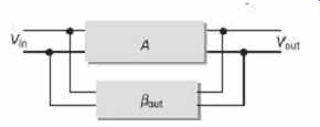
FIG. 1 Basic feedback circuit employed in oscillators
Oscillators generate a continuous voltage output waveform at a required frequency with the values of the inductors, capacitors or resistors forming a frequency selective LC resonant (or tank) feedback network. The oscillator frequency is regulated using a tuned or resonant inductive/capacitive circuit with the resulting output frequency being known as the oscillation frequency. So, the feedback path of the oscillator is made reactive. The phase angle of the feedback will vary as a function of frequency and this is called phase shift. Certain conditions are required to fulfill for sustained oscillations and these conditions are that (a) the loop gain of the circuit must be equal to or greater than unity, and (b) the phase shift around the circuit must be zero. These two conditions for sustained oscillations are called Barkhausen criteria.
2.2 Resonance
If a constant voltage with varying frequency is impressed to a circuit consisting of an inductor, capacitor and resistor, then the reactance of both the capacitor-resistor (RC) and inductor-resistor ( RL ) paths are to change both in amplitude and in phase of the output signal as compared to the input signal. At high frequencies the reactance of a capacitor is very low and it acts as a short circuit while the reactance of the inductor is high and it acts as an open circuit. At low frequencies, the reverse is true, meaning the reactance of the capacitor acts as an open circuit and the reactance of the inductor acts as a short circuit.
Between these two boundaries, the combination of the inductor and capacitor produces a tuned or resonant circuit that has a resonant frequency ( f r ) in which the capacitive and inductive reactances are equal and cancel out each other, leaving only the resistance of the circuit to oppose the flow of current and as a result of that, there is no phase shift as the current is in phase with the voltage. Based on this concept subsequent sections of the chapter are explained.
2.3 Basic LC Oscillatory Circuit
As shown in FIG. 2 , the circuit consists of an inductive coil L and a capacitor C. The capacitor stores energy in the form of an electrostatic field and which produces a potential or static voltage across it, while the inductive coil stores its energy in the form of a magnetic field. The capacitor is charged up to the dc supply voltage V by putting the switch in the position A. When the capacitor is fully charged, the switch is thrown to the position B and the charged capacitor is now connected in parallel across the inductive coil so the capacitor begins to discharge itself through the coil. The voltage across C starts falling as the coil. The voltage across C starts falling as the current through the coil begins to rise. This rising current sets up an electromagnetic field around the coil and when C is completely discharged, the energy that was originally stored in the capacitor C as an electrostatic field is now stored in the inductive coil L as an electromagnetic field around the coil windings. As there is now no external voltage in the circuit to maintain the current within the coil, it starts to fall as the electromagnetic field begins to collapse. A back emf is induced in the coil (e = −Ldi/dt ) keeping the current flowing in the original direction.
This current now charges the capacitor C with the opposite polarity to its original charge.
C continues to charge until the current has fallen to zero and the electromagnetic field of the coil has collapsed completely. The energy originally introduced into the circuit through the switch has been returned to the capacitor which again has an electrostatic potential across it, although it is now of the opposite polarity. The capacitor now starts to discharge again back through the coil and the whole process is repeated, with the polarities changed and continues as the energy is passed back and forth producing an ac type sinusoidal voltage and current waveform.
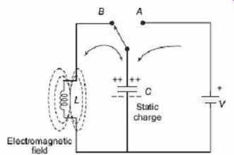
FIG. 2 Basic LC oscillator circuit
This oscillatory action of transferring energy from the capacitor C to the inductor, L and vice versa, would continue indefinitely if there is no loss of energy in the circuit. But, energy is lost in the resistance of the inductor coil, in the dielectric of the capacitor, and in radiation from the circuit; so the oscillation steadily decreases until it dies away completely. Then in a practical LC circuit, the amplitude of the oscillatory voltage decreases at each half cycle of oscillation and will eventually die away to zero. The oscillations are then said to be damped. The quality factor of the circuit sets the amount of damping. In FIG. 3, damped oscillations are shown in both the cases, with small R and with large R.
The frequency of the oscillatory voltage depends upon the value of the inductance and capacitance in the LC circuit. We know when resonance has to occur, both the capacitive X C and inductive X L reactances must be equal and opposite to cancel out each other. As a result, the resistance in the circuit remains to oppose the flow of current. Then the frequency at which this will happen is given as...
Resonant frequency in a tuned LC circuit, the output frequency, To maintain the oscillations keeping the amplitude at a constant level, in an LC circuit, it is required to replace the energy lost in each oscillation. The amount of energy replaced must be equal to that lost during each cycle. Alternatively, if the amount of energy replaced is too small, the amplitude would decrease to zero over time. The simplest way of replacing this energy is to take part of the output from the LC circuit, amplify it and then feed it back into the LC circuit again and this can be achieved using a voltage amplifier. To produce a constant oscillation, the level of the energy fed back to the LC network must be accurately controlled. Then there must be some form of automatic amplitude or gain control when the amplitude tries to vary from a reference voltage either up or down. To maintain a stable oscillation the overall gain of the circuit must be equal to 1 or unity. Any less and the oscillations will not start or die away to zero, any more the oscillations will occur but the amplitude will become clipped by the supply rails causing distortion. A circuit containing this feature is considered in the next section.
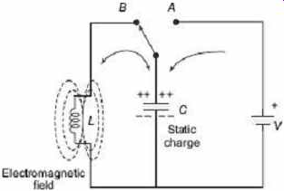
FIG. 3 Damped oscillations
2.4 Basic Transistor LC Oscillator Circuit
A BJT is used as the oscillator amplifier and the tuned LC circuit acts as the collector load as shown in FIG. 4 . A second coil L 2 is connected between the base and emitter.
Electromagnetic field of L 2 is mutually coupled with that of the coil L. Mutual inductance exists between two circuits. The changing current in one circuit induces by electromagnetic induction a potential in the other due to transformer action. So as the oscillations take place in the tuned circuit, electromagnetic energy is transferred from the coil L to the coil L 2 and a voltage of the same frequency as that in the tuned circuit is applied between the base and emitter of the transistor. In this way, the necessary automatic feedback voltage is obtained. The amount of feedback can be varied by changing the coupling between coils L and L 2 . When the circuit is oscillating, its impedance is resistive and the collector and base voltages are 180° out of phase. In order to maintain oscillations, the voltage applied to the tuned circuit must be in-phase with the oscillations occurring in the tuned circuit. So, it is necessary to introduce an additional 180° phase shift into the feedback path between the collector and base. This is done by winding the coil of L2 in the correct direction relative to the coil L giving us the correct amplitude and phase relationships for the oscillator circuit or by introducing a phase shift network between the output and input of the amplifier.
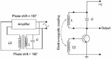
FIG. 4 Basic transistor LC oscillator
LC oscillators are actually sinusoidal oscillators or harmonic oscillators that can generate high-frequency sine waves for use in Radio Frequency (RF) Type applications with the transistor amplifier being a BJT or FET. There are different ways to construct LC filter networks and amplifiers. As a result, harmonic oscillators come in different forms and the most common forms are Hartley LC oscillator, Colpitts LC oscillator, Armstrong oscillator, Clapp oscillator, etc.
2.5 Oscillator Summary
A few basic requirements for an oscillatory circuit are given as follows:
1. The circuit should contain a reactive or frequency dependent component-either an Inductor (L) or a Capacitor ( C ) and a dc supply voltage.
2. Overall gain of the amplifier circuit must be at least unity.
3. Self-regenerative or positive feedback results oscillations.
4. Oscillations of the circuit become damped due to circuit losses.
5. To overcome these circuit losses, voltage amplification is necessary.
6. Desired oscillations can be maintained by using some part of the output voltage as feedback to the tuned circuit that is of the correct amplitude and in-phase (0°).
7. To keep the output signal in phase with the input, the overall phase shift of the circuit must be zero.
3. HARTLEY OSCILLATOR
The basic LC oscillator circuit does not have the option of controlling the amplitude of the oscillations. A weak electromagnetic coupling between L and L 2 results in insufficient feedback and the oscillations would eventually die away to zero. Similarly, a strong feedback causes the oscillations to increase in amplitude until they are limited by the circuit conditions producing distortion. It is possible to feed back exactly the right amount of voltage for constant amplitude oscillations. If the feedback is more than what is necessary, the amplitude of the oscillations can be controlled by biasing the amplifier in such a way that if the oscillations increase in amplitude, the bias is increased and the gain of the amplifier is reduced. If the amplitude of the oscillations decreases, the bias decreases and the gain of the amplifier increases, thus, increasing the feedback. This is the method to keep oscillations constant and it is known as automatic base bias. Efficient oscillator can be implemented by employing a class-B or even class-C bias as the collector current flows during only part of the cycle and the quiescent collector current is very small. Then this self-tuning base oscillator circuit forms the basic configuration for the Hartley oscillator circuit.
In the Hartley oscillator, the tuned LC circuit is connected between the collector and the base of the transistor amplifier and as far as the oscillatory voltage is concerned, the emitter is connected to a tapping point on the tuned circuit coil. A Hartley oscillator can be implemented from any configuration that uses either a single-tapped coil or a pair of series-connected coils in parallel with a single capacitor.
3.1 Basic Hartley Oscillator Circuit
FIG. 5 shows the basic Hartley oscillator circuit. During oscillation, the voltage at the point X (collector), relative to the point Y (emitter), is 180° out-of-phase with the voltage at the point Z (base) relative to the point Y . At the frequency of oscillation, the impedance of the collector load is resistive and an increase in base voltage causes a decrease in the collector voltage. Then there is a 180° phase change in the voltage between the base and collector and this along with the original 180° phase shift in the feedback loop provides the correct phase relationship of positive feedback for oscillations to be maintained. The position of tapping point of the inductor sets the amount of feedback. If it is moved nearer to the collector, the amount of feedback is increased, but the output taken between the collector and ground is reduced and vice versa. Resistors R 1 and R 2 are there for the usual stabilizing dc bias for the transistor in the normal manner while the capacitors act as dc blocking capacitors. In this circuit, the dc collector current flows through a part of the coil and for this reason, the circuit is said to be series-fed with the frequency of oscillation of the Hartley oscillator being given as where, L = L 1 + L 2 .
Note: L is the total inductance if two separate coils are used.
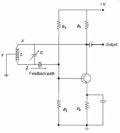
FIG. 5 Basic Hartley oscillator
The frequency of oscillations can be adjusted by varying the tuning capacitor C or by varying the tap position of the inductive coil, giving an output over a wide range of frequencies making it very easy to tune. In the series-fed Hartley oscillator, it is also possible to connect the tuned tank circuit across the amplifier as a shunt-fed oscillator discussed as follows.
3.2 Shunt-fed Hartley Oscillator Circuit
As shown in FIG. 6 , in the shunt-fed Hartley oscillator, both the ac and dc components of the collector current have separate paths around the circuit. Here, a very small amount of power is wasted in the tuned circuit. Since the dc component is blocked by the capacitor C2 , no dc component flows through the inductive coil, L. The Radio Frequency Coil (RFC) L 2 is an RF choke which offers a high reactance at the frequency of oscillations so that most of the RF current is applied to the LC tuning tank circuit via the capacitor, C2 as the dc component passes through L2 to the power supply. A resistor could be used in place of the RFC coil but the efficiency would be less.
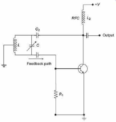
FIG. 6 Shunt-fed Hartley oscillator
Example 1
One Hartley oscillator circuit has two inductors of 0.5 mH and each is tuned to resonate with a capacitor which can be varied from 100 pF to 500 pF. Determine the upper and lower frequencies of oscillation and the oscillator bandwidth.
Solution
The circuit consists of two inductive coils in series.
The total inductance is given as:
Upper frequency, Lower frequency, Oscillator bandwidth
4. COLPITTS OSCILLATORS
The Colpitts oscillator is somewhat opposite to the Hartley oscillator as the centre tapping is made from capacitive voltage divider network instead of tapped inductive coil as shown in FIG. 7 . Similar to the Hartley oscillator, the tuned tank circuit consists of an LC resonance circuit connected between the collector and base of the transistor amplifier.
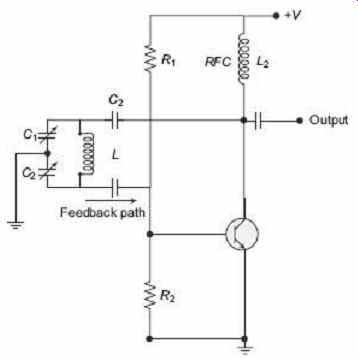
FIG. 7 Basic Colpitts oscillator circuit
The emitter of the transistor amplifier is connected to the junction of capacitors C1 and C2 which are connected in series with the required external phase shift obtained in a similar manner to that in the Hartley oscillator. The amount of feedback is controlled by the ratio of C1 and C2 which are generally ganged together to provide a constant amount of feedback. Once again, the frequency of oscillations for a Colpitts oscillator is determined by the resonant frequency of the LC tank circuit and is given as where C T is the capacitance of C 1 and C 2 connected in series and is given as.
A common emitter-amplifier configuration is employed here, with the output signal 180° out of phase with respect to the input signal. The two capacitors are connected together in series but in parallel with the inductive coil resulting in overall phase shift of the circuit being zero. Resistors R 1 and R 2 are used for the usual stabilizing dc bias for the transistor in the normal manner while the capacitor acts as dc-blocking capacitors.
Example 2
One Colpitts oscillator circuit has two capacitors of 10 pF and 100 pF respectively connected in parallel with an inductor of 10 mH. Determine the frequency of oscillations of the circuit.
Solution
The circuit consists of two capacitors in series.
So, the total capacitance is given as If the inductor is of 10 mH then the frequency of oscillation is Then the frequency of oscillations for the oscillator is 527.8 kHz.
5. THE RC OSCILLATOR
So far, only LC tuned circuits that cause phase shift of 180° due to inductive or capacitive coupling in addition to a 180° phase shift produced by the transistor or op-amp, have been discussed. Such LC oscillators are employed to generate high-frequency oscillations but they cannot be employed for generation of low frequency oscillations as they become too bulky and expensive. RC oscillators are commonly used for generating audio-frequencies as they provide good frequency stability and waveform. When an RC network is connected in class-A configuration, a single stage amplifier will produce 180° of phase shift between its output and input signals. If an oscillator has to oscillate a sufficient positive feedback of the correct phase must be provided with the amplifier being used as an inverting stage to achieve this. In an RC oscillator, the input is shifted 180° through the amplifier stage and 180° again through a second inverting stage giving 360° (180° + 180°) of phase shift which is the same as 0° thereby providing the required positive feedback.
This method of phase shift between the input to an RC network and the output from the same network is employed in a resistance-capacitance oscillator or simply an RC oscillator.
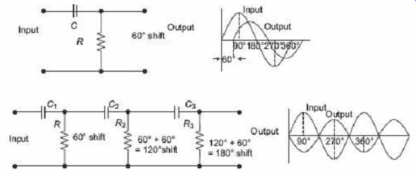
FIG. 8 RC phase-shift network
In FIG. 8 , the circuit on the top shows a single resistor-capacitor network and whose output voltage leads the input voltage by some angle less than 90°. An ideal RC circuit would produce a phase shift of exactly 90°, as it is known that the amount of actual phase shift in the circuit depends upon the values of the resistor, capacitor and the chosen frequency of oscillations. The phase angle ( Ф ) is given as In this simple example above, the values of R and C have been chosen so that at the required frequency, the output voltage leads the input voltage by an angle of about 60°.
Then by cascading or connecting together three such RC networks in series, it is possible to produce a total phase shift in the circuit of 180° at the chosen frequency and it forms the basis of an RC oscillator circuit. It is known that in an amplifier circuit, either using a BJT or Op-AMP, it will produce a phase-shift of 180° between its input and output. If an RC phase-shift network is connected between this input and output of the amplifier, the total phase shift will become 360°, i.e. the feedback is in-phase.
5.1 Basic RC Oscillator Circuit
The RC oscillator as shown in FIG. 9 , which is called a phase-shift oscillator, produces a sine-wave output signal using regenerative feedback from the resistor-capacitor combination.
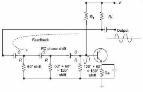
FIG. 9 Basic RC oscillator circuit
This regenerative feedback from the RC network is possible due to the capability of the capacitor to store an electric charge. The resistor-capacitor feedback network can be connected as shown above to produce a leading phase shift or interchanged to produce a lagging phase and the outcome is still the same as the sine-wave oscillations only occur at the frequency at which the overall phase shift is 360°. By varying one or more of the resistors or capacitors in the phase-shift network, the frequency can be varied and generally this is done using a 3-ganged variable capacitor. If all the resistors R and the capacitors C are equal in value then the frequency of oscillations produced by the oscillator is given where f is the output frequency in Hz, R is the resistance in ohms, C is the capacitance in farads, N is the number of RC stages and in our example, N = 3
5.2 The Op-amp ffC Oscillator
Operational Amplifier (Op-amp) RC oscillators are more common than their bipolar transistor counterparts. The RC network that produces the phase shift is connected from the op-amps output back to its non-inverting input as shown in FIG. 10 .
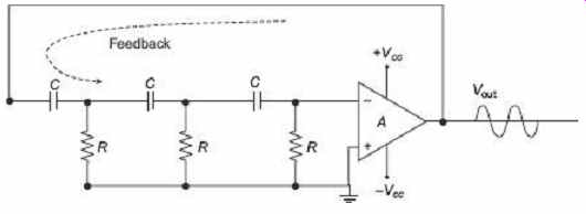
FIG. 10 Operational-amplifier RC oscillators
The feedback is connected to the non-inverting input and the operational amplifier is connected in its inverting amplifier configuration which produces the required 180° phase shift. The RC network produces the other 180° phase shift at the required frequency.
Although it is possible to cascade together two RC stages to provide the required 180° of phase shift, but in that case the stability of the oscillator at low frequencies is poor. One of the most important characteristics of an RC oscillator is its frequency stability. This is the ability of an oscillator to provide a constant frequency output under varying load conditions. So to obtain higher frequency stability, three or even four RC stages together are cascaded. RC oscillators with four stages are widely used because commonly available operational amplifiers come in quad IC packages. So, designing a 4-stage oscillator with 45° of phase shift relative to each other is comparatively easy. RC oscillators are stable and provide a well-shaped sine-wave output with the frequency being proportional to 1/ RC . Using a variable capacitor, a wider frequency range is possible. However, the use of RC oscillators are restricted to low-frequency applications, because of their bandwidth limitations to produce the desired phase shift at high frequencies.
Example 3
Determine the frequency of oscillations of a RC oscillator circuit having three-stages each with a resistor and capacitor of equal values. R = 10 kΩ and C = 500 pF
Solution
Here, R = 10 kΩ, C = 500 pF, N = 3
Therefore, the frequency of oscillation is given as
6. WIEN BRIDGE OSCILLATORS
The Wien bridge oscillator is another type of oscillator which uses a RC network in place of the conventional LC tuned circuit to produce a sinusoidal output waveform. The Wien bridge oscillator is a two-stage RC coupled amplifier circuit that has good stability at its resonant frequency, low distortion and is very easy to tune making it a popular circuit as an audio frequency oscillator. The phase shift of the output signal is considerably different from the previous RC oscillators.
The Wien bridge oscillator employs a feedback circuit consisting of a series RC circuit connected with a parallel RC of the same component values producing a phase delay advance (lag-lead) circuit depending upon the frequency as shown in FIG. 11.
The above RC network is a typical second-order frequency dependent band-pass filter with high quality factor( Q ). It consists of a low-pass filter (series RC network) and another high-pass filter (parallel RC network). At low frequencies, the reactance Xc of the series capacitor is very high so the series capacitor acts like an open circuit and blocks any input signal V in and therefore there is no output signal V out . At high frequencies, the reactance of the parallel capacitor is very low so the parallel capacitor acts like a short circuit on the output, so again there is no output signal. However, between these two extremes, the output voltage reaches a maximum and the frequency at which this happens is called the resonant frequency (f r ) as the circuit's reactance equals its resistance X c = R. At this resonant frequency, the output voltage is one third (1/3) of the input voltage.
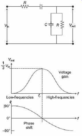
FIG. 11 RC phase shift network;
FIG.
12 Output gain and phase shift
It can be seen as in FIG. 12 that at very low frequencies, the phase angle between the input and output signals is positive, i.e. leading in nature, while at very high frequencies the phase angle becomes negative, i.e. lagging in nature. In the middle of these two points the circuit is at its resonant frequency ( f r ) with the signals being in-phase or 0°. The expression of resonant frequency is as follows:
This frequency-selective RC network forms the basis of the Wien Bridge oscillator circuit. The Wien bridge oscillator circuit is produced by placing this RC network across a non-inverting amplifier. As in FIG. 13 , the output of the operational amplifier is fed back to the inputs in-phase with part of the feedback signal connected to the inverting input terminal via the resistor divider network of R 1 and R 2 , while the other part is fed back to the non-inverting input terminal via the RC network. Then at the selected resonant frequency ( f r), the voltages applied to the inverting and non-inverting inputs will be equal and in-phase. So the positive feedback will cancel the negative feedback signal causing the circuit to oscillate. Also the voltage gain of the amplifier circuit should be 3 as set by the resistor network, R 1 and R 2.
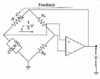
FIG. 13 Wien bridge oscillator with op-amp
Example 4
Determine the maximum and minimum frequency of oscillations of a Wien bridge oscillator circuit having a resistor of 10 kΩ and a variable capacitor of 1 nF to 1000 nF.
Solution
The frequency of oscillations for a Wien bridge oscillator is given as:
Lowest frequency, Highest frequency, ...