AMAZON multi-meters discounts AMAZON oscilloscope discounts
1. INTRODUCTION
A data acquisition system is a device or an integrated system used to collect information about the state or condition of various parameters of any process. For example, collecting day-to-day temperature of a particular location can be termed data acquisition . Say, a person recording the level of municipal water-storing tank into a piece of paper, is actually performing the task of a data acquisition system. With the advancement of digital electronics, various electronic devices have been developed to perform this kind of recording or logging job.
Now a days, most data acquisition systems are integrated with computer, sensors, signal conditioning devices, etc. and the function of these kind of data acquisition systems varies for simple recording of process parameter to control of industrial system. These kinds of systems basically have a hardware and a software part. The hardware part consists of a sensor, signal conditioning, analog-to-digital converter, memory, processor, switches, digital-to-analog converter, etc. and the software part consist, of operating system, editor, graph display program and data processing software, etc.
A data acquisition system is used in various applications, starting from industry to scientific laboratories.
The actual definition of a data acquisition system also varies; here is a common definition of data acquisition system.
"Data acquisition is the process by which physical phenomena from the real world are transformed into electrical signals that are measured and converted into a digital format for processing, analyzing, and storage by a computer".
2. BASIC COMPONENTS OF DATA ACQUISITION SYSTEMS
The basic elements of a data acquisition system, as shown in the functional diagram ( Figure 1) are as follows:
- Sensors and transducers
- Field wiring
- Signal conditioning
- Data acquisition hardware
- PC (operating system)
- Data acquisition software
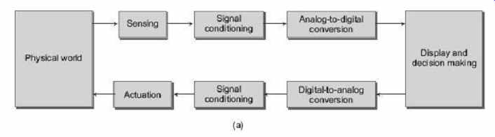
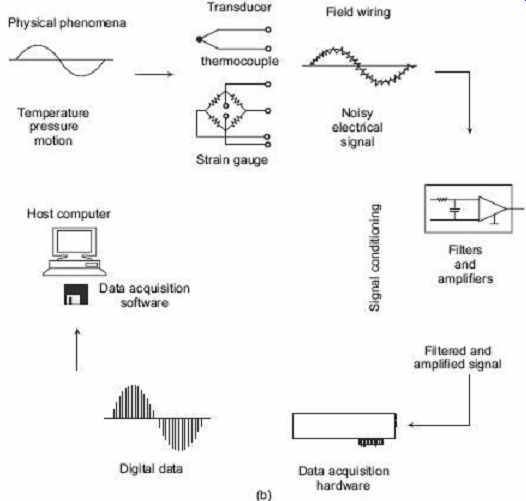
Figure 1 (a) and (b) Functional diagram of a data
acquisition system
We can think of a data acquisition system as a collection of software and hardware that connects us to the physical world. A typical data acquisition system consists of these components.
Table 1 Components of a data acquisition system
Components | Description
Data acquisition hardware
The main function of this hardware is to convert analog signals to digital signals, and to convert processed digital signals to analog signals.
Sensors and actuators (transducers)
Transducer/Sensor converts input energy from one form to another form. For example, a thermocouple converts heat energy into electrical. An actuator also converts energy from one form to another, which is often connected at the output of a data acquisition system in order to manipulate the final control element.
Signal conditioning hardware
Sensor signals are often not compatible with data acquisition hardware. To overcome this incompatibility, the signal must be conditioned. For example, we may need to condition the thermocouple output signal by amplifying it or by removing unwanted frequency components. Output signals may also need conditioning.
Computer
The computer provides a processor, a system clock, a bus to transfer data, and memory and disk space to store data.
Software
It allows exchanging information between the computer and the hardware. For example, typical software allows us to configure the sampling rate of our board, and acquire a predefined amount of data.
3. COMPONENTS OF A TYPICAL PC-BASED DATA ACQUISITION SYSTEM
Earlier, expensive mainframe computers were used extensively for gathering multiple channels of data, primarily in large industrial or scientific applications. They were seldom used in small projects because of their relatively high cost. But the introduction of small rack-mounted minicomputers that developed in the 1960's and later desktop personal-type computers that housed microprocessors and proliferated in the 1970's justified their use for smaller projects. Soon, data acquisition plug-in cards (as well as hundreds of other types of plug-in cards) for these small computers were a common means to collect and record data of all types.
3.1 DAQ Hardware
A Data Acquisition System (DAQ) is a combination of computer hardware and software that gathers stores or processes data in order to control or monitor some sort of physical process. A typical data acquisition system comprises a computer system with DAQ hardware, wherein the DAQ hardware is typically plugged into one of the I/O slots of the computer system. The DAQ hardware is configured and controlled by DAQ software executing on the computer system. Data acquisition hardware is either internal and installed directly into an expansion slot inside your computer, or external and connected to your computer through an external cable, which is typically a USB cable.
At the simplest level, data acquisition hardware is characterized by the subsystems it possesses. A subsystem is a component of data acquisition hardware that performs a specialized task. Common subsystems include Analog input Analog output Digital input/output Counter/timer Hardware devices that consist of multiple subsystems, such as the one depicted below, are called multifunction boards.
1. Analog Input Subsystems
Analog input subsystems convert real-world analog input signals from a sensor into bits that can be read by your computer. Perhaps the most important of all the subsystems commonly available, they are typically multichannel devices offering 12 or 16 bits of resolution.
Analog input subsystems are also referred to as AI subsystems, A/D converters, or ADCs.
Analog-to-Digital Conversion In data acquisition systems, it is necessary to convert one or several analog signals into one or several digital signals capable of being stored in a digital memory and processed by a digital processor. Analog signals must be digitized before they can be used by a computer as a basis for supporting computations. An analog-to-digital converter is an electrical device that converts an analog signal to a digital signal. When the analog signal has been converted to a digital signal, it can be processed and stored by computer systems. An analog-to-digital converter is often fabricated on a single integrated circuit. The details of an analog input subsystem will be discussed in latter.
2. Analog Output Subsystems
Analog output subsystems convert digital data stored on your computer to a real-world analog signal. These subsystems perform the inverse conversion of analog input subsystems. Typical acquisition boards offer two output channels with 12 bits of resolution, with special hardware available to support multiple channel analog output operations.
Analog output subsystems are also referred to as AO subsystems, D/A converters, or DACs.
3. Digital Input/Output Subsystems
Digital input/output (DIO) subsystems are designed to input and output digital values (logic levels) to and from hardware. These values are typically handled either as single bits or lines, or as a port, which typically consists of eight lines.
While most popular data acquisition cards include some digital I/O capability, it is usually limited to simple operations, and special dedicated hardware is often necessary for performing advanced digital I/O operations.
4. Counter/Timers Subsystems
Counter/Timer subsystems are designed to count the number of pulses coming from external devices and the timers are normally used to provide strict time count of delay time
3.2 Sensors and Transducers
Transducer/Sensor converts input energy from one form to another form. According to the type, output sensors are classified in two types: digital sensors and analog sensors.
The sensors which can produce a digital output signal, that is a digital representation of the input signal, having discrete values of magnitude measured at discrete times, are called digital sensors . A digital sensor must output logic levels that are compatible with the digital receiver. Examples of digital sensors include switches and position encoders.
Analog sensors produce an output signal that is directly proportional to the input signal, and is continuous in both magnitude and in time. Most physical variables such as temperature, pressure and acceleration are continuous in nature and are readily measured with an analog sensor. For example, some common analog sensors and the physical variables they measure are listed below.
Table 2 Common analog sensors
Sensor Physical Variable Thermocouple Temperature Microphone Pressure, Pressure gauge, Pressure Photodiode Light intensity, Strain gauge Force LVDT Displacement
When choosing the best analog sensor to use, you must match the characteristics of the physical variable you are measuring with the characteristics of the sensor. The two most important sensor characteristics are The sensor output The sensor bandwidth
3.3 Signal Conditioning
Most sensors and transducers generate signals that must be conditioned before a measurement or DAQ device can reliably and accurately acquire the signal. This front-end processing is referred to as signal conditioning. A signal conditioner may create excitation for certain transducers such as strain gauges and resistance temperature detectors, which require external excitation voltages or currents. The main tasks performed by signal conditioning are as follows:
Filtering Amplification Linearization Isolation Excitation
Filtering
In noisy environments, it is very difficult to acquire low magnitude signals received from sensors such as signals from thermocouples and strain gauges (in the order of mV). If the noise is of the same or greater order of magnitude than the required signal, the noise must first be filtered out. Signal conditioning equipment often contain low-pass filters designed to eliminate high-frequency noise that can lead to inaccurate data.
Filtering is a process by which the unwanted noise frequencies are removed from the source signal. This is done before the signal is amplified to feed to the DAQ system.
Ideally, a filter should have a very sharp cut-off frequency, in order to separate the useful frequencies from the noise frequencies. However, most practical filters do not accurately attenuate the undesired frequencies beyond the desired range.
In general, analog filter hardware consists of two types of filters-namely active filters and passive filters.
While active filters use components like OP-AMPs, passive filters consist of passive components like capacitors, inductors and resistors. They provide cheap hardware for filtering action. However, such filters are not ideal and they do not accurately attenuate the noise amplitudes.
In intelligent signal-conditioning modules, however, integrating A/D converters go a long way to averaging (filtering) out any cyclical noise appearing at the input.
Alternatively, software averaging may also be used to eliminate periodic system noises such as mains hum.
Filters have certain attributes which define them. They are as following:
1. Cut-off Frequency
It is the frequency beyond which the filter attenuates all the frequencies. It can be highpass or low-pass cut-off frequency as required by the device. In general, cut-off frequency is considered as frequency where the normalized gain of the signal drops below 0.707 times the maximum gain.
2. Roll Off
This is the slope of the amplitude versus the frequency graph at the region of the cut-off frequency. This characteristic differentiates an ideal filter from a non-ideal filter.
3. Quality Factor
This factor determines the gain of the filter at the resonant frequency and the roll-off of the transfer characteristics on both sides of the resonant frequency.
Active filters are more frequently used as against the passive filters due to their sharper roll-of and better stability.
4. Types of Filters
There are four kinds of filters, namely Low-pass filter High-pass filter Band-pass filter Band-stop filter
(a) Low-Pass Filter A low-pass filter allows the low frequencies to pass while attenuates the higher frequencies. Figure 2 shows the ideal low-pass filter characteristics, where ω p is the filter cut-off frequency. Figure 3 shows the circuit diagram of an active low-pass filter. The actual filter response deviates from the original when implemented. Figure 4 shows the practical filter characteristics.
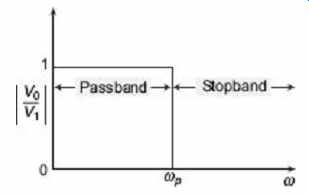
Figure 2 Ideal low-pass filter characteristics
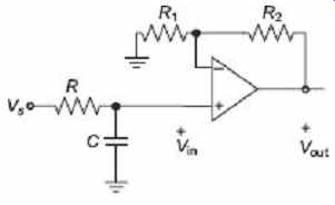
Figure 3 Circuit diagram of an active low-pass filter
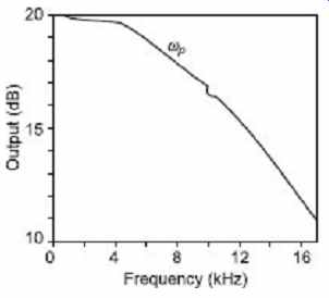
Figure 4 Practical low-pass filter characteristics
Figures 2 and 3 shows the circuit diagram and the transfer characteristics of a low-pass filter respectively. As we can see, a low-pass filter allows the low frequencies to pass while attenuates the higher frequencies.
(b) High-Pass Filter A high-pass filter allows the high frequencies to pass while attenuates the lower frequencies. Figure 5 shows the ideal high-pass filter characteristics, where w p is the filter cut-off frequency. Figure 6 shows the circuit diagram of an active highpass filter. The actual filter response deviates from the original when implemented. Figure 7 shows the practical filter characteristics.
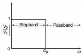
Figure 5 Ideal high-pass filter characteristics
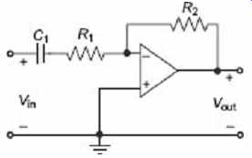
Figure 6 Circuit diagram of an active high-pass
filter
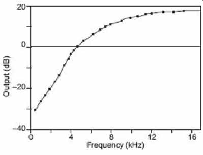
Figure 7 Practical high-pass filter characteristics
(c) Band-Pass (selective) Filter These are filters which allow frequencies within a certain range, bound by an upper (w p 2) and a lower (w p 1) cut-off frequency to pass through, attenuating other frequencies. These are also known as selective filters and they combine a low-pass and a high-pass filter in series to give selected band of frequency allowance.
Figure 8 and 9 shows the characteristics of band-pass filter for an ideal and a real filter respectively.
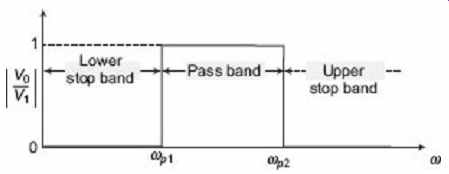
Figure 8 Ideal band-pass filter characteristics
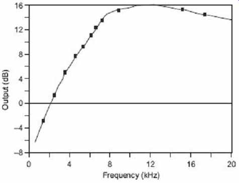
Figure 9 Practical band-pass filter characteristics
(d) Band-stop (Notch) Filters This kind of filter attenuates a certain band of frequencies and lets all other frequencies to pass through. They use a parallel combination of a high and low-pass filters to give the required attenuation of a band of frequencies. They are also known as notch. Figure 10 and 11 show the ideal and practical band-stop filter characteristics of a band-stop filter.
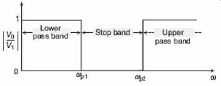
Figure 10 Ideal band-stop filter characteristics
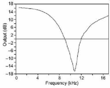
Figure 11 Ideal band-stop filter characteristics
(e) Butterworth Filter This is a kind of active filter which provides a better level of low-pass filtering. This is achieved by cascading two or more stages of low-pass filters. The number of stages of filtering determines how sharp the roll-off is at the cut-off frequency. Figure 12 shows a two-stage Butterworth filter.
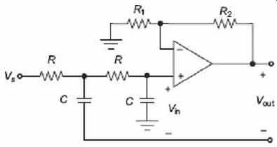
Figure 12 A two-stage Butterworth filter
5. Amplification
It is a process by which an input signal of weak signal strength (low amplitude) is converted into a signal of higher signal strength (high amplitude), so as to be readable by the processing devices.
In signal conditioning, amplification serves two main purposes:
Increases resolution of the input signal Increases Signal-to-Noise ratio (SNR) Amplification mainly serves for increasing resolution of the input signal. If, for example, a low-level signal of the order of a few mV is fed to a 12-bit ADC, there will be a loss of precision as the resolution of the ADC is of the order of 2 mV. However, if the signal is amplified to the order of 10 V (full scale voltage for ADC), we get the maximum precision. The highest possible resolution can be achieved by amplifying the input signal so that the maximum input voltage swing equals the maximum input range of the ADC.
Another important function of amplification is to achieve high signal-to-noise ratio.
Amplifying a signal before sending it through a cable to the receiving end enables high SNR to the noises introduced in the path having noise interference. This ensures the improved precision of the measurement. If, however, the signal is amplified after the noise interference causes low SNR which implies the noise causes a considerable error in the input signal.
6. Linearization
It is the modification of a system so that its outputs are approximately linear functions of its inputs, in order to facilitate analysis of the system.
It is seen that sometimes the data output by transducers bear a non-linear relationship with the measured phenomenon over a range of the measured variable. A good example of such relation is thermocouples. Such non-linear relationships need to be properly linearized for analysis of data. Typically, the DAQ software facilitates the linearization of the signals. However, if the signal has a periodic and repeatable non-linear relation, an intelligent signal conditioning hardware may as well provide such linearization. This however, requires the signal conditioning module to be modified for a particular type of transducer. The result then can be sent directly to the host PC directly without undergoing linearization as the signal is directly related to the measured phenomenon.
7. Isolation
Signal-conditioning equipment can also be used to provide isolation of transducer signals from the computer where there is a possibility that high-voltage transients may occur within the system being monitored, either due to electrostatic discharge or electrical failure. Isolation protects expensive computer equipment from damage and computer operators from injury. In addition, where common-mode voltage levels are high or there is a need for extremely low common-mode leakage current, as for medical applications, isolation allows measurements to be accurately and safely obtained.
Isolation in signal conditioning refers to the transmission signal from the source to measuring device without physical connection. The most common methods of circuit isolation include opto-isolation, magnetic or capacitive isolation. While opto-isolation is used for digital signals, magnetic and capacitive isolations are used for analog signals.
Magnetic or capacitive isolation involves the modulation of the signal converting it from voltage to frequency signal and the transmitting it over a transformer or a capacitor, when it is again converted back to a voltage signal.
Isolation of the signal source is very crucial where there is a risk of high voltage transients caused by electrostatic discharge, lightning, or high-voltage equipment failure, which may ruin the expensive DAQ equipment if not isolated from the signal source and may also cause serious injuries to humans handling the equipment. Also using isolation prevents complexities caused by common-mode voltages and ground loops.
System isolation can be carried out in the following ways:
- By using isolation transformer in order to reject the common-mode voltage appearing on the signal lines.
- By using buffer amplifiers to isolate the input signals from ground noise.
- By isolating system ground references.
8. Excitation
The transducers generally provide for the excitation signals required by the DAQ hardware and data manipulation. However, in some cases, the transducers require external excitation due to weak signal generation, non-electrical signal generation or due to noise interference and other factors. The signal-conditioning hardware provides for such excitation signals. The transducers which convert the non-electrical values into electrical (voltage or current) signals are known as active transducers. These transducers do not generally require external excitation. Other devices known as passive transducers change an electrical network value, such as resistance, inductance or capacitance, according to changes in the physical quantity being measured. Strain gauges (resistive change to stress) and LVDTs (inductance change to displacement) are two examples of this. To be able to detect such changes, passive devices require external excitation.
3.4 The Computer
The PC used in a data acquisition system can greatly affect the speeds at which data can be continuously and accurately acquired, processed, and stored for a particular application.
Where high-speed data acquisition is performed with a plug-in expansion board, the throughput provided by bus architectures, such as the PCI expansion bus, is higher than that delivered by the standard ISA or EISA expansion bus of the PC.
The particular application, the microprocessor speed, hard-disk access time, disk capacity and the types of data transfer available, can all have an impact on the speed at which the computer is able to continuously acquire data. All PCs, for example, are capable of programmed I/O and interrupt-driven data transfers. The use of Direct Memory Access (DMA), in which dedicated hardware is used to transfer data directly into the computer's memory, greatly increases the system throughput and leaves the computer's microprocessor free for other tasks. In normal operation, the data acquired, from a plug-in data acquisition board or other DAQ hardware (e.g. data logger), is stored directly to system memory. Where the available system memory exceeds the amount of data to be acquired, data can be transferred to permanent storage, such as a hard disk, at any time.
The speed at which the data is transferred to permanent storage does not affect the overall throughput of the data acquisition system.
If real-time processing of the acquired data is needed, the performance of the computer's processor is paramount. A minimum requirement for high-frequency signals acquired at high sampling rates would be a 32-bit processor with its accompanying coprocessor, or alternatively a dedicated plug-in processor. Low frequency signals, for which only a few samples are processed each second, would obviously not require the same level of processing power. A low-end PC would, therefore, be satisfactory. Clearly, the performance requirements of the host computer must be matched to the specific application. As with all aspects of a data acquisition system, the choice of computer is a compromise between cost and the current and future requirements it must meet.
One final aspect of the personal computer that should be considered is the type of operating system installed. This may be single-tasking (e.g. MS-DOS) or multitasking (e.g. Windows 2000). While the multitasking nature of Windows provides many advantages for a wide range of applications, its use in data acquisition is not as clear.
The computer provides a processor, a system clock, a bus to transfer data, and memory and disk space to store data. The processor controls how fast data is accepted by the converter. The system clock provides time information about the acquired data. Data is transferred from the hardware to system memory via Dynamic Memory Access (DMA) or interrupts. DMA is hardware controlled and therefore extremely fast. Interrupts might be slow because of the latency time between when a board requests interrupt servicing and when the computer responds. The maximum acquisition rate is also determined by the computer's bus architecture.
3.5 Software
Regardless of the hardware you are using, you must send information to the hardware and receive information from the hardware. You send configuration information to the hardware such as the sampling rate, and receive information from the hardware such as data, status messages, and error messages. You might also need to supply the hardware with information so that you can integrate it with other hardware and with computer resources. This information exchange is accomplished with software. There are two kinds of software:
Driver software Application software
1. Driver Software
It allows us to access and control the capabilities of hardware. Among other things, basic driver software allows us to Bring data on to and get data off the board Control the rate at which data is acquired Integrate the data acquisition hardware with computer resources such as processor interrupts, DMA and memory Integrate the data acquisition hardware with signal-conditioning hardware Access multiple subsystems on a given data acquisition board Access multiple data acquisition boards
2. Application Software
It provides a convenient front end to the driver software. It allows us to Report relevant information such as the number of samples acquired Manage the data stored in computer memory Condition a signal Plot acquired data