AMAZON multi-meters discounts AMAZON oscilloscope discounts
1. INTRODUCTION
Rising costs and the inflexibility of hard-wired relay systems have stimulated the development of Programmable Logic Controllers (PLCs) as an alternative. The PLC can be defined as a user-friendly; microprocessor-based specialized equipment that carries out control functions of many types and levels of complexity for use in industry. Its purpose is to monitor crucial process parameters and adjust process operations accordingly. It can be programmed, controlled, and operated by users. PLCs use a programmable memory to store instructions and to implement functions such as logic, sequencing, timing, counting and arithmetic in order to control machines and processes. PLCs are designed to be operated by users with perhaps a limited knowledge of computer and computing languages. Generally, a PLC's operator draws the lines and devices of ladder diagrams with a keyboard into a display screen. Then, the resulting drawing is converted into computer machine language and run as a user program.
In a traditional industrial control system, all control devices are wired directly to each other according to how the system is supposed to operate. The PLC replaces the wiring between the devices. Thus, instead of being wired directly to each other, all equipment is wired to the PLC. Then, the control program inside the PLC provides the wiring connection between the devices. The control program is the computer program stored in the PLC's memory that tells the PLC what's supposed to be going on in the system. If anybody wants a PLC system to behave differently or to control a different process element, just the control program is required to change. In a traditional system, making this type of change would involve physically changing the wiring between the devices, a costly and time-consuming endeavour.
The existing push buttons, limit switches, and other command components continue to be used, and become input devices to the PLC. In like manner, the contactors, auxiliary relays, solenoids, indicating lamps, etc., become output devices controlled by the PLC. If one understands the interface between the hardware and the software, the transition to PLCs is relatively easy to accomplish.
2. ADVANTAGES OF PLCs
PLCs have been gaining popularity on the factory floor and will probably remain predominant for some time to come. Most of this is because of the advantages they offer.
Cost effective for controlling complex systems.
Flexible and can be reapplied to control other systems quickly and easily.
Computational abilities allow more sophisticated control.
Trouble shooting aids make programming easier and reduce downtime.
Reliable components make these likely to operate for years before failure.
Expandability.
Ability to withstand harsh environments.
Small space requirements.
PLC circuit's operation can be seen during the operation directly on a monitor.
3. THE CONTROL PROGRAM
A person knowledgeable in relay logic systems can master the major PLC functions in a few hours. These functions include coils, contacts, a timer and counters. The same is true for a person with a digital-logic background. For a person unfamiliar with digital and relay logics, however, the learning process takes more time. PLCs are not designed so that only computer programmers can set up or change the programs. Thus, the designers of the PLC have pre-programmed it so that the control program can be entered using a simple, rather intuitive form of language. So, the control program instructs the PLC system how to react to each input signal from, say, switches and give the required outputs to, say, lamps, motors and valves. A program might have a form as follows:
If switch A or B close Then output to lamp circuit If switch A and B close Output to motor circuit
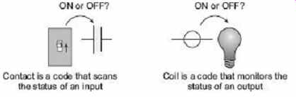
FIG. 1 Contacts and coils
In a PLC, switches, sensors or input devices are realised as contacts and output circuits as coils. The term logic in a PLC is used because programming is primarily concerned with implementing logic and switching operations. Input devices such as sensors, switches and output devices in the system being controlled, e.g. lamp, motor etc., are connected to the PLC. The operator then enters a sequence of instructions, i.e. a control program, into the memory of the PLC. The controller then monitors the inputs ( contacts) and outputs ( coils) according to this control program and carries out the control rule for which it has been programmed.
4. FUNCTION OF EACH PART IN PLC
A PLC consists of the CPU, memory and circuits for inputs and outputs. Input and output circuits deal with receiving input data and sending data to output devices respectively. A PLC may be considered to be a collection of a large number of relays, counters, timers and data-storage locations. These components (timers, counters, etc.) do not exist physically but, are used as logical components. The block diagram of the internal structure of a PLC is shown in FIG. 2.
1. Input Relays (Contacts)
These components are actually transistors, exist physically and are meant for receiving signal from sensors, switches, etc.
2. Internal Utility Relays (Contacts)
They are logical (simulated) relays and are the main tools of a PLC which eliminate the use of conventional physical relays and finally, hard-wired relay control circuits. These are useful components to implement control logic programs.
3. Output Relays (Coils)
They do exist physically, made of transistors, conventional relay, etc., depending upon applications and are used to send on/off signals to lamps, solenoids etc.
4. Counters
These are programmed to count the number of events (pulses). They do not exist physically. These logical components are used for the sake of implementing control programs containing the need of counting up or down or both, a series of events.
5. Timers
These exist logically. These are used to introduce time delay between the occurrence of two events. Timers are of different types, like, on-delay timers, off-delay timers, retentive type, etc.
6. Data Storage
These are basically a group of registers, used to store data to carry out arithmetic and logical operations with them. This is a very essential part of a PLC.

FIG. 2 Block diagram of the internal structure
of PLC
5. HARDWARE OF PLC
Typically, a PLC system has three basic functional components. The three major parts are central processing unit (CPU), Input/output module and programming terminals. FIG. 3 shows how these three parts are interconnected.
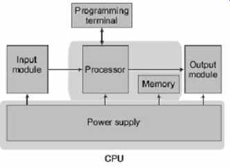
FIG. 3 Block diagram of PLC hardware
5.1 The Central Processing Unit (CPU)
CPU controls and processes all the operations within the PLC. It is supplied with a clock frequency of typically between 1 and 8 MHz. This frequency decides the operating speed of a PLC and provides the timing and synchronization for all elements in the system. The CPU acts as the "brain" of the system, which has three subparts:
1. Processor
It contains the microprocessor. This interprets the input signals and carries out mathematic and logic operations to set the control actions, according to the program stored in the memory, and finally, communicates the decisions as action signals to the output. This part does the following functions:
(a) Updating Inputs and Outputs
This function allows a PLC to read the status of its input terminals and activate or de-activate its output terminals.
(b) Performing Logic and Arithmetic Operations
For this an Arithmetic and Logic Unit (ALU) is there. It is responsible for data manipulation and carrying out arithmetic operations of addition and subtraction and logic operations of AND, OR, NOT, XOR.
(c) Communicating with Memory As data and programs are stored in the memory, the CPU needs to communicate with the memory throughout the operation.
(d) Scanning Application Programs
The scanning function allows the PLC to execute the application program as specified by the programmer.
(e) Communicating with a Programming Terminal
The programming terminal is used to load programs and data into the CPU. So, in PLC programming mode, the CPU has to constantly communicate with the programming terminal.
A PLC uses four buses to carry out communication process when binary information is transferred from one location to another. Those buses are data bus, address bus, control bus and system bus.
Data bus carries the data used in the processing carried out by the CPU. This is a bidirectional bus as the CPU has to perform both data/instruction read and write operation through this bus.
Address bus used to carry the address of memory locations or I/O devices to identify a particular memory register or I/O device with which the read/write operation is conducted by CPU.
Control bus carries the signals used by the CPU for control actions, e.g. to inform memory devices whether they are to receive data from an input device or to send data to an output device. This bus is employed to carry timing signals used to synchronize actions.
System bus is used for communications between the input/output ports and input/output units.
2. Memory
It is the area of the CPU in which data and information are stored and retrieved. It is there to hold the system software and user programs. As shown in FIG. 4 , the memory is used to store different files. File is the collection of words and a word has two bytes, lower byte and higher byte . Eight bits make a word. Bit is the smallest unit of information, either high or low. To store a bit, the smallest unit of memory is known as a memory cell . A register is a group of memory cells. For example, eight memory cells connected in parallel forms an eight-bit register. So, to store a word (2 bytes), two such registers are to be used.
To identify memory locations, it is very essential to adopt an addressing scheme which may be octal or hexadecimal.
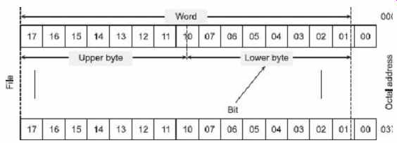
FIG. 4 Bit, byte, word, file relationships
A PLC memory system has both ROM and RAM. PLC operating-system programs are stored permanently into ROM, whereas information can be stored and retrieved into/from the RAM. The programs and data in RAM can be changed by the user. However, to prevent the loss of programs when the power supply is switched off, a battery is used in the PLC to maintain the RAM contents for a period of time. User programs (say, ladder logic program) can be written into the RAM and a new program can overwrite previously written programs in the same locations. Apart from these possibly, as a bolt-on extra module, erasable and programmable read-only-memory (EPROM) is available and it can be programmed and then the program made permanent. After a program has been developed in RAM, it may be loaded into an EPROM memory and made permanent. In addition, there are temporary buffer storage for input/output modules. Memory capacity, often expressed in terms of kilo-bytes, can vary from PLC to PLC.
3. Power Supply
It is a section of CPU which converts ac line voltage to various operational dc values. The power supply makes regulated dc voltage with proper filtering circuit to ensure the supply of desired low dc voltage levels to the processor and circuits in the input and output modules.
5.2 The Input/Output (I/O) Modules
The input/output module provides the interface between the system and the outside world, allowing for connections to be made through input/output channels to input and output devices. The input module has terminals into which outside process electrical signals, generated by sensors or transducers, are fed. The output module has terminals to which output signals are sent to activate relays, solenoids, various solid-state switches, motors, indicators and displays. A very simple control scheme using a PLC has been shown in FIG. 5 .
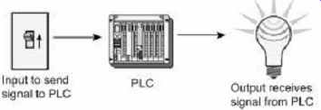
FIG. 5 Input and output schemes in a PLC
It is also through the input/output module that programs are entered from a programming terminal. Every input/output point has a unique address which can be used by the CPU for identifying the device. The input/output channels provide isolation and signal-conditioning functions so that sensors and actuators can often be directly connected to them without the need for other circuitry. Electrical isolation from the external world is usually by means of opto-isolators (opto-coupler).
An electronic system for connecting I/O modules to remote locations can be added if needed. The actual operating process under PLC control can be hundreds of meters from the CPU and its I/O modules. Input and output devices can be classified as giving signals which are discrete or digital or analog as shown in FIG. 6 . Analog devices give signals whose size is proportional to the size of the variable being monitored. For example, a variable potential divider has no definite on-state, i.e. signals coming from these types of devices may have any value in between off or zero (minimum) and on or one (maximum). Digital devices have two distinct states on and off and they can give a sequence of on-off signals.
Outputs are specified as being of relay type, transistor type or triac type.
For faster switching operation or response, transistor-type output is preferred over relay-type output. Off Relay-type output isolates the PLC from the external circuit. But in the transistor type, opto-isolators are used to provide isolation. Triac output with optoisolator can be used to control external loads which are strictly connected to ac power supply.
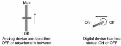
FIG. 6 Digital and analog devices
Outputs to actuators allow a PLC to cause something to happen in a process. Few popular actuators are solenoid, valves, lights/indicator (normally, to test designed logic circuits), motor starters, servomotors, etc. Typical examples of sensors used as inputs to PLC are switches, potentiometers, LVDTs (Linear Variable Differential Transformers), etc.
The way in which dc devices are connected to a PLC can be described with the terms sourcing and sinking . With sourcing, using the conventional current-flow direction as from positive to negative, an input device receives current from the input module, i.e. the input module acts as the source of the current ( FIG. 7 (a)). If the current flows from the output module to an output device or load, the output module is referred to as sourcing.
[ FIG. 7 (b)]. With sinking, using the conventional current-flow direction as from positive to negative, an input device is the sink for the current [ FIG. 7 (c)]. If the current flows to the output module from an output device or load then the output module is referred to as sinking [ FIG. 7 (d)].
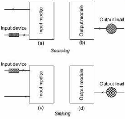
FIG. 7 Sourcing and sinking of I/O devices
There are two common types of mechanical design for PLC systems; a single box, and the modular/ rack types. The single-box type (sometimes called brick) is commonly used for small programmable controllers and is supplied as an integral compact package complete with power supply, processor, memory, and input/output units. Typically, such a PLC might have 6, 8, 12 or 24 inputs and 4, 8 or 16 outputs. Some box or brick PLC systems have the options to extend more input and output by linking input/output boxes.
Systems with larger numbers of inputs and outputs are likely to be modular and designed to fit in racks. Rack is an enclosure with slots on which the CPU, power supply and I/O modules are mounted. The rack type can be used for all sizes of programmable controllers and has various functional units packaged in individual modules which can be plugged into slots according to requirement. Thus, it is comparatively easy to expand the number of inputs/outputs by just adding more I/O modules or to expand the memory by adding more memory units as shown in FIG. 8.
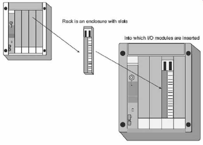
FIG. 8 Rack and I/O module arrangement
5.3 PLC Programming Terminal
The programming terminal connects PLC programmer/monitor (PM) to CPU by a cable.
PLC programming equipment exists to allow the user to write, edit and monitor a program, as well as perform various diagnostic procedures. PLC programming arrangements can be a hand-held device, a desktop console or a personal computer.
Hand-held programming will normally contain enough memory to allow the unit to retain programs while being carried from one place to another.
Desktop consoles are likely to have a visual display unit with a full keyboard.
Personal computers are widely configured as program development workstations. Some PLCs only require the computer to have appropriate software; others require special communication cards to interface with the PLC.
Every brand of PLC has its own programming hardware. Sometimes, it is a small handheld device that resembles an oversized calculator with a Liquid Crystal Display (LCD).
Computer-based programmers typically use a special communication board, installed in an industrial terminal or personal computer, with the appropriate software program installed.
Computer-based programming allows offline programming, where the programmer develops his her logic, stores it on a disk, and then downloads the program to the CPU at his her convenience. In fact, it allows more than one programmer to develop different modules of the program. Programming can be done directly to the CPU if desired. When connected to the CPU, the programmer can test the system, and watch the logic operate as each element is intensified in sequence on the CRT when the system is running. Since a PLC can operate without having the programming device attached, and one device can be used to service many separate PLC systems. The programmer can edit or change the logic online in many cases.
6. SYSTEM ADDRESSING
The knowledge of addressing systems or schemes is a must to implement and execute a control program in a PLC. Input devices like push buttons, limit switches, etc., are to be connected with the controller to feed input commands and then execution of the control program brings the results out through output devices like motor starters, solenoids, and light bulbs, etc., connected with the system. Inputs and outputs are wired to interface modules, installed in an I/O rack. Normally, each rack has a two-digit address, each slot has its own address, and each terminal point is numbered.
6.1 I/O Addresses
At the time of relay logic or ladder-diagram implementation, all input and output devices connected with the PLC are identified by unique addresses. As it has already been discussed, I/O modules are kept in the rack. In a PLC system, each rack can be identified by a two-digit address. In each rack, slots are there to place input and output cards. Again, the slots are numbered (say, 0 to 7). For example, assuming an input card has eight input channels which are numbered (00 to 07). Now, as shown in FIG. 9 , in a typical PLC, to connect two switches (one push button and another temperature switch) with the input card, placed in slot 3 of rack 01, two channels or terminals of that input card are to be used (say, 01 and 03). So, the assigned address to the push-button switch becomes I:013/01 and for the temperature sensor, is I:013/03. More precisely, in an input/output device address, the first alphabet indicates device type ('I' for input device or 'O' for output device) followed by a colon (:) and then, the next two digits indicate the rack number followed by the slot number and after a slant (/), the terminal number or bit number.
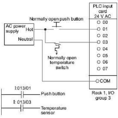
FIG. 9 An input card and ladder logic
6.2 Image Table Addresses
As shown in FIG. 10 , in a PLC system, one file is reserved as an input image table.
Every word in that file has a three-digit octal address beginning with 1:, which can be interpreted as the letter I for input. The word addresses start with octal 1:000 to 1:017 (or higher). This number is also followed by a slant (/) and the 2-digit bit number.
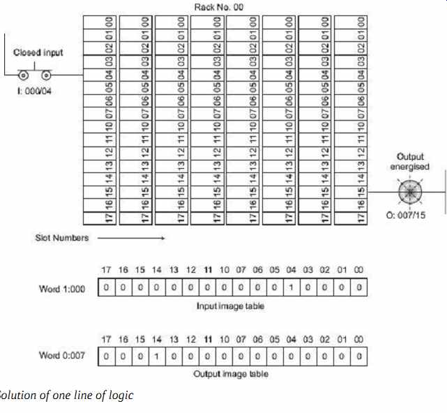
FIG. 10 Solution of one line of logic
In FIG. 10 , the input address I:000/04, becomes memory address I:000/04, and the output address O:007/14 becomes memory address O:007/14. In other words, type of module, rack address, and slot position identify the word address in memory. The terminal number identifies the bit number.
6.3 Remote I/O
So far it has been assumed that a PLC consists of a CPU, power-supply unit, and a collection of I/O cards mounted in the local rack. In the early days, PLCs did tend to be arranged like this, but in a large and scattered plant with this arrangement, all signals have to be brought back to some central point using expensive multicore cables. It will also make commissioning and fault finding more difficult, as signals can only be monitored effectively at a point possibly some distance from the device being tested.
PLC manufacturers, therefore, provide the ability to mount I/O racks remote from the processor, and link these racks with simple and cheap screened pair of fiber optic cables.
If remote I/O is used, provision should be made for a program terminal to be connected local to each rack. Remote I/O allows complete units to be built, wired to a built-in rack, and tested offsite prior to delivery and installations. FIG. 11 shows three remote racks, and connects to the controlling PLC mounted in a substation far away, via a remote I/O cable, plus a few power supplies and hardware safety signals.
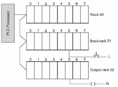
FIG. 11 Remote I/O racks
7. PLC OPERATION AND PROGRAM SCAN
A PLC program can be considered to behave as a permanent running loop as shown in FIG. 12 (a). The actions carried out by a PLC shown in FIG. 12 (a) is called program scan , and the period of the loop is called program scan time . This depends on the size of the PLC program and the speed of the processor.
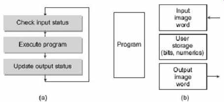
FIG. 12 Three steps in PLC operation
At start, the PLC scans the state of all the connected inputs and stores their states in the PLC memory. When PLC program accesses an input, it reads the input state as it was at the start of the program scan. A zone of PLC memory corresponding to the outputs is changed by the execution of the program, and then, all the outputs are updated simultaneously at the end of the scan. The action is thus read inputs , execute program , update outputs . Therefore, a PLC does not communicate continuously with the outside world.
PLC memory can be considered to consist of four zones or areas as shown in FIG. 12 (b). The inputs are read into the input mimic area at the start of the scan called input image word (explained earlier), and the output updated from the output mimic zone or area called output image word at the end of the scan. There will be an area in the memory reserved for internal signals which are used by the program but are not connected directly to the outside world (timers, counters, latches, etc.). These three areas are often referred to as data table or database. As indicated in FIG. 13, total response time is the sum of input response time, program execution time and output response time.
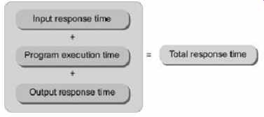
FIG. 13 PLC response time