AMAZON multi-meters discounts AMAZON oscilloscope discounts
(cont. from part 1)
8. IMPLEMENTATION OF CONTROL PROGRAMS IN PLC
PLCs from different manufacturers can be programmed in various ways. Popular programming languages for PLCs are ladder diagrams, Function Block Diagrams (FBD), and statement list. With a few exceptions, a program written in one format can be viewed in another.
8.1 Ladder Diagrams
As an introduction to ladder diagram, consider the simple relay circuit which contains a coil and contacts as shown in FIG. 14. When a voltage is applied to the input coil, the resulting current creates a magnetic field. The magnetic field pulls a metal switch (or reed) towards it and the contacts touch, closing the switch. The contact that closes when the coil is energized is called normally open (NO). The Normally Closed (NC) contacts touch when the input coil is not energized. When the input coil is not energized, the normally closed contacts will be closed (conducting). The relay shown in the figure has two contacts; one NO another NC. When the relay coil is energized, contacts of the relay change their state, i.e. NO contacts get closed and NC contacts get opened. The relay arrangement can be shown with the help of different schematic circuits as shown in FIG. 14. Relays are normally drawn in a schematic form using a circle to represent the input coil. The output contacts are shown with two parallel lines. NO contacts are shown as two lines, and will be open (nonconducting) when the input is not energized. NC contacts are shown with two lines with a diagonal line through them. Now, if it is required to operate NO (C) contact of this relay, connected to an ac source, through two input relay contacts,
A (NC) and B (NO) then the relay logic diagram shown in FIG. 15 is the most appropriate for a typical logic. According to the relay logic diagram shown in the figure, activation of the input relay coil corresponds to the contact B , makes C (output) closed and activation of the input relay coil corresponds to the contact A , makes C (output) to get opened. This sort of arrangement is normally employed in conventional hard-wired relay logic circuit.
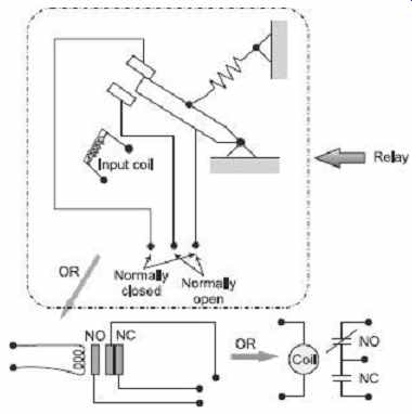
FIG. 14 Simple relay layouts and schematics
The same scheme can be implemented following ladder logic as shown in FIG. 15 .
The ladder logic-diagram is the most commonly used method of programming PLCs. The ladder diagram consists of two vertical lines representing the power rails. Circuits connected as horizontal lines between two rails are called rungs of the ladder. Few symbols used to denote ladder logic inputs and outputs are shown in FIG. 16 and 17 respectively. Taking into consideration these ladder logic symbols, the ladder logic implemented in FIG. 15 mimics the same hard-wired relay logic. Finally, this ladder logic is inserted as a control program to a PLC where, input devices, and output devices are arranged in a fashion as illustrated in FIG. 18 . So, the ladder-logic programs are loaded into the PLC, the input and output devices are connected to I/O modules and then the execution of the program updates outputs according to the status of inputs.
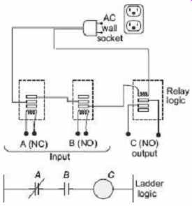
FIG. 15 A simple relay controller and corresponding
ladder-logic
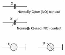
FIG. 16 Ladder logic inputs; FIG. 17 Ladder
logic Normal Output
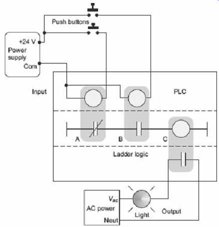
FIG. 18 A PLC illustrated with relays
Many relays also have multiple outputs and this allows an output relay to also be an input simultaneously. The circuit shown in FIG. 19 is an example of this and it is called a seal-in circuit . In this circuit, the current can flow through either branch of the circuit, through the contacts labeled A or B . The input B will only be on when the output B is on. If B is off, and A is energized then B will turn on. If B turns on then the input B will turn on, and keep output B on even if input A goes off. After B is turned on, the output B will not turn off.
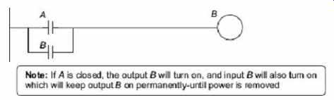
FIG. 19 A seal-in circuit
Another example of ladder logic can be seen in FIG. 20 . To interpret this diagram, imagine that the power is on the vertical line on the left-hand side, called hot rail. On the right-hand side is the neutral rail. In the figure there are two rungs, and on each rung there are combinations of inputs (two vertical lines) and outputs (circles). If the inputs are opened or closed in the right combination, the power can flow from the hot rail, through the inputs, to power the outputs, and finally to the neutral rail. An input can come from a sensor, switch, or any other type of sensor. An output will be some device outside the PLC that is switched on or off, such as lights or motors. In the top rung, the contacts are normally open and normally closed, which means if input A is on and input B is off then power will flow through the output and activate it. Any other combination of input values will result in the output X being off.
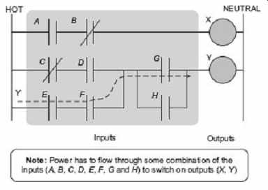
FIG. 20 A simple ladder logic diagram
Example 1 Try to develop (without looking at the solution) a relay-based controller that will allow three switches in a room to control a single light.
Solution There are two possible approaches to this problem. The first assumes that any one of the switches on will turn on the light, but all three switches must be off for the light to be off. The ladder logic is shown in FIG. 21.
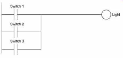
FIG. 21 Ladder logic to controlling one light
with three switches
The second solution assumes that each switch can turn the light on or off, regardless of the states of the other switches. This method is more complex and involves thinking through all of the possible combinations of switch positions. You might recognize this problem as an exclusive or problem. The ladder logic is as shown in FIG. 22.
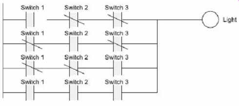
FIG. 22 Ladder logic to controlling one light
in a different way with three switches
Note: It is important to get a clear understanding of how the controls are expected to work. In this example, two radically different solutions were obtained based upon a simple difference in the operation.
8.2 Function Block Diagram
Function Block diagram (FBD) is used for PLC programs described in terms of graphical blocks. It is described as being a graphical language for depicting signal and data flows through Inputs blocks, these being reusable software elements. A function block is a program instruction unit which, when executed, yields one or more output values. Thus, a block is represented in a manner shown in FIG. 23 with the function name written in the block. Functional blocks can have standard functions, such as those of the logic gates or counter or timers or have functions defined by the user, e.g. a block to obtain an average value of inputs.
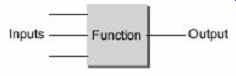
FIG. 23 Function block
8.3 Statement List
In statement-list programming approach, an instruction set similar to assembly language for a microprocessor is used. Statement lists, available on few brands of PLCs, are the most flexible form of programming for the experienced user but are by no means as easy to follow as ladder diagrams or logic symbols.
FIG. 24 shows a simple operation in ladder-diagram form for a Mitsubishi PLC.
The equivalent statement list would be as shown in Table 1 .
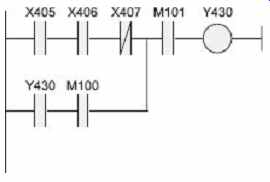
FIG. 24 Mitsubishi ladder diagram
Table 1 Equivalent statement list for FIG. 24
Line Instruction Comment
0 LD X405 LD starts rung or branch 1 AND X406 Xnnn are inputs (AND-ing is for series connection) 2 ANI X407 ANI is AND with not 3 LD Y430 LD starts a new branch leg 4 ANI M100 Mnnn are internal storage 5 ORB OR the two branch legs (OR-ing for parallel connection) 6 AND M101 7 OUT Y430 End of rung with output
8.4 Logic Functions
There are many control situations requiring actions to be initiated when a certain combination of conditions is realised. Thus, for an automatic drilling machine, there might be a condition that the drill motor is to be activated when limit switches are activated that indicate the presence of the workpiece and the drill position as being at the surface of the workpiece. Such situation involves the AND logic function, condition A and condition B having both to be satisfied for an output to occur. Similarly, other situations may demand to implement logics like OR, NOT, NAND, NOR, XOR. The electric circuit, truth table, ladder diagram and functional block diagram for different logics are presented in Table 2 .
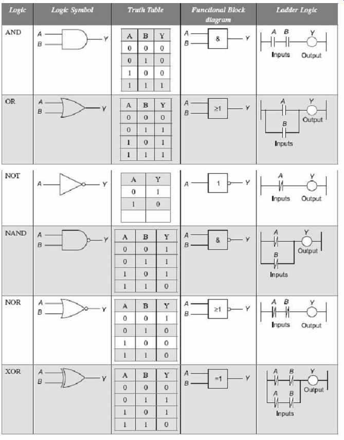
Table 2 Characteristics for different logics
9. MORE IN LADDER LOGIC
Combinational logic alone is not enough to implement control programs for more complex systems, especially, those with event-based devices. The example of such event-based system is illustrated in FIG. 25 with a timing diagram. The input to the device is a push button. When the push button is pushed, the input to the device turns on. If the push button is then released and the device turns off, it is a logical device. If when the push button is released and the device stays on, it will be a type of event-based device. To reiterate, the device is event based if it can respond to one or more things that have happened before. If the device responds only one way to the immediate set of inputs, it is logical. To implement such event-based devices in ladder logic diagrams, some components are available in PLC programming approach. Latches, timers, counters are the most frequently used components used in ladder diagrams.
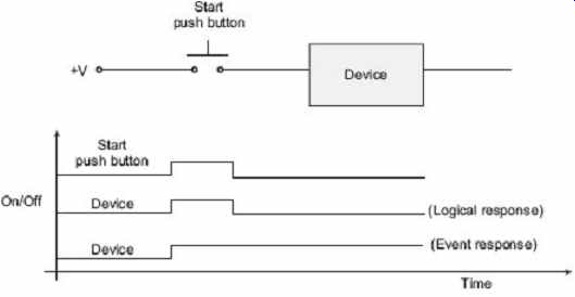
FIG. 25 An event driven device
9.1 Latches or Set-reset Coils
Another function which is often available is the ability to latch and unlatch (set and reset) an internal relay. A latch is just like a sticky switch-when pushed, it will turn on and will continue with its on-state, it must be pulled to release it and turn it off. A latch in ladder logic uses one instruction to latch, and a second instruction to unlatch, as shown in FIG. 26 . The output with an L inside will turn the output D on when the input A becomes true. D will stay on even if A turns off and this makes C to turn off. Output D will turn off if input B becomes true and the output with a U inside becomes true. If an output has been latched on, it will keep its value, even if the power has been turned off.

FIG. 26 A ladder logic latch
9.2 Timers
The most commonly used process-control device after coils and contacts is the timer.
There are four fundamental types of timers as illustrated in Table 3. A single input timer, called a non-retentive timer , is used in some PLCs. An example of such a timer is shown in FIG. 27 . Energizing IN001 causes the timer to run for 8 seconds. At the end of 8 seconds, the output goes on. An on-delay timer will wait for a set time after a line of ladder logic has been true before turning on, but it will turn off immediately. An off-delay timer will turn on immediately when a line of ladder logic is true, but it will delay before turning off. An on-delay timer can be used to allow an oven to reach a certain temperature before starting production. An off-delay timer can keep cooling fans on for a set time after the oven has been turned off.
Table 3 Four basic timer types
On-delay Off-delay
Non-retentive On-delay timer (TON) Off-delay timer (TOF) Retentive Retentive on-delay timer (RTO) Retentive off-delay timer (RTF)
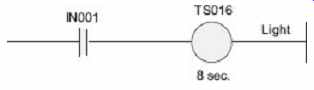
FIG. 27 Single-input timer
A retentive timer will sum all of the on or off time for a timer, even if the timer is never finished. A nonretentive timer will start timing the delay from zero each time. Typical applications for retentive timers include tracking the time before maintenance is needed. A non retentive timer can be used for a start button to give a short delay before a conveyor begins moving.
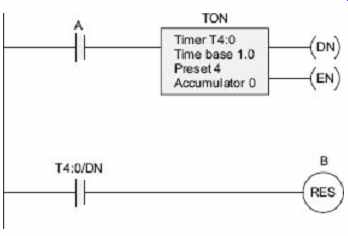
FIG. 28 Example of TON timer
An example of a TON timer is shown in FIG. 28 . The rung has a single input A and a function block for the TON. (Note: This timer block will look different for different PLCs, but it will contain the same information.) The information inside the timer block describes the timing parameters. The first item is the timer number T4:0 (or address). This is a location in the PLC memory that will store the timer information. The T4: indicates that it is timer memory, and the 0 indicates that it is in the first location. The time base is 1.0 indicating that the timer will work in 1.0 second intervals. Other time bases are available in fractions and multiples of seconds. The preset is the delay for the timer, in this case it is 4. To find the delay time, multiply the time base by the preset value 4*1.0 s = 4.0s. The accumulator value gives the current value of the timer as 0. While the timer is running, the accumulated value will increase until it reaches the preset value. Whenever the input A is true, the EN output will be true. The DN output will be false until the accumulator has reached the preset value. The EN and DN outputs cannot be changed when programming, but these are important when debugging a ladder-logic program. The second line of ladder logic uses the timer DN output to control another output B.
9.3 Counters
There are two basic counter types: count-up and count-down. When the input to a count-up counter goes true, the accumulator value will increase by 1 (no matter how long the input is true.) If the accumulator value reaches the preset value, the counter DN bit will be set. A count-down counter will decrease the accumulator value until the preset value is reached.
A count-up (CTU) instruction is shown in FIG. 29 . The instruction requires memory in the PLC to store values and status, in this case, it is C4:0. The C4: indicates that it is counter memory, and the 0 indicates that it is the first location. The preset value is 4 and the value in the accumulator is 2. If the input A goes from false to true, the value in the accumulator would increase to 3. If A is turned off, then on again the accumulator value would increase to 4, and the DN bit would turn on. The count can continue above the preset value. If input B goes true the value in the counter accumulator will become zero.
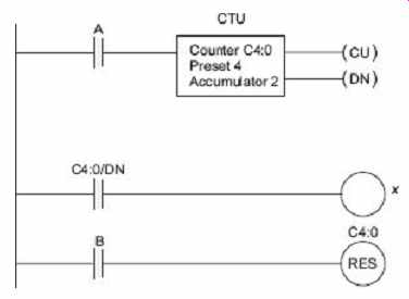
FIG. 29 CTU counter
9.4 Master Control Relays (MCRs)
Master Control Relay (MCR) function is a powerful programming tool. When MCR is enabled, the ladder diagram functions normally. When it is not enabled, a specific number of coils and functions are frozen in the off position. Coils in the frozen section will remain off even if their corresponding enable lines are turned on. In an electrical control system, a master control relay is used to shut down a section. A section of ladder logic can be put between two lines containing MCRs. When the first MCR coil is active, all of the intermediate ladder logic is executed up to the line with another MCR coil. When the first MCR coil is inactive, the ladder logic is still examined, but all of the outputs or coils are forced off.
Take the example in FIG. 30 . If A is true then the ladder logic is executed normally. But, if A is false, the following ladder logic will be examined, but all of the outputs will be forced off. The second MCR function appears on a line by itself and marks the end of the MCR block. After the second MCR, the program execution returns to normal mode. In this example, while A is true, condition of X will equal to B. As Y is a latch, it can be turned on by C , and can be turned off by D . But, if A becomes false, X will be forced off, and Y will continue with its last state. Using MCR blocks to remove sections of programs will not increase the speed of program execution significantly because the logic is still examined.
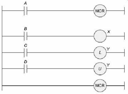
FIG. 30 MCR instructions
9.5 More Examples on Timers and Counters
Example 2 Develop the ladder logic that will turn on an output light, 15 seconds after the switch A has been turned on.
Solution The ladder diagram for this problem is shown in FIG. 31. An on-delay timer block with 15-seconds delay has been used and it is being activated by the switch A , and the contact present in the second rung is closed to turn on the light when the 15 second delay is elapsed.
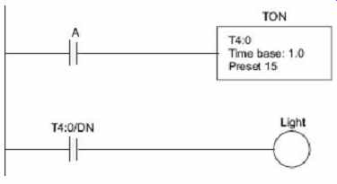
FIG. 31 A simple timer example
Example 3 Develop the ladder logic that will turn on a light, after the switch A has been closed 10 times. Push button B will reset the counters.
Solution The ladder diagram to implement this logic is shown in FIG. 32 where the up-counter block keeps the count of pressing the switch A . When the count reaches the preset value of the counter, the contact C5 in the second rung, corresponding to the counter, is closed and the light is turned on. To reset the counter the reset coil of the counter is energized by the switch B present in third rung.
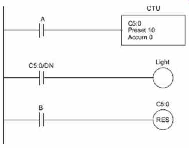
FIG. 32 A simple counter example
QUIZ
Objective-type Questions
1. PLCs are __ designed for use in the control of a wide variety of manufacturing machines and systems.
(a) special-purpose industrial computers; (b) personal computers; (c) electromechanical systems; (d) all of the above
2. The first company to build PLCs was: (a) general motors; (b) Allen Bradley; (c) square D; (d) Modicon
3. Which of the following statements is not correct? (a) The PLC rung output [-( )-] is a discrete output instruction or bit in memory.
(b) Each rung of the ladder logic represents a logical statement executed in software-inputs on the right and outputs on the left.
(c) Input and output instructions in ladder logic do not directly represent the switches and actuators.
(d) PLC input instructions are logical symbols associated with voltage at the input module terminals.
4. Which of the following statements is NOT correct? (a) The status of each input can be checked from one location and outputs can be forced on and off.
(b) All symbols in the RLL represent actual components and contacts present in the control system.
(c) PLCs are not as reliable as electromechanical relays in RLL.
(d) Input (-| |-) and output (- ( ) -) instruction symbols in the ladder logic represent only data values stored in PLC memory.
5. When a relay is NOT energized, (a) there is an electrical path through the NO contacts (b) there is an electrical path through the NC contacts (c) neither the NO or the NC contacts have an electrical path (d) both the NO and the NC contacts have an electrical path
Short-answer Questions
1. Can a PLC input switch a relay coil to control a motor?
2. Develop a simple ladder logic program that will turn on an output X if any one of the inputs A , B and C is on.
3. Develop a simple ladder logic program that will turn on a motor operated by the output X if the input A is on and motor will turn off if the input B is on.
4. What are the benefits of input/output modules of a PLC?
5. How do input and output cards act as an interface between the PLC and external devices?
Long-answer Questions
1. Give a concise description of hardware of a PLC.
2. Draw a block diagram showing in very general terms the main units in a PLC.
3. Why would relays be used in place of PLCs? Give an example of where a PLC could be used. List the advantages of a PLC over relays.
4. Explain why ladder logic outputs are coils. Develop a simple ladder logic program that will turn on an output X if inputs A and B , or input C is on.
5. Can a PLC input switch a relay coil to control a motor? How do input and output cards act as an interface between the PLC and external devices? What are the benefits of input/output modules?
6. Explain why a stop button must be normally closed and a start button must be normally open. Explain the tradeoffs between relays and PLCs for control applications.