AMAZON multi-meters discounts AMAZON oscilloscope discounts
1. History
Today, there is a standard test method for the transmission line pulse (TLP) test methodology. The standard test method for TLP test simulation is supported by the electrostatic discharge (ESD) Association (ANSI/ESD-ESD-STM 5.5.1--2008). The standard test method was developed with a cable length that is consistent with the energy under the human body model (HBM) waveform. Today, there are significant research as well as commercial TLP test systems that support this TLP test method.
TLP systems are designed in different configurations. TLP system configurations include current source, time domain reflectometry (TDR), time domain transmission (TDT), and time domain reflectometry and transmission (TDRT) [1-3]. In all configurations, the source is a transmission line whose characteristic time constant is determined by the length of the transmission line cable. The various TLP configurations influence the system characteristic impedance, the device under test (DUT) location, and the measurement of the transmitted or reflected signals. For this method, the choice of pulse width is determined by the interest to use TLP testing as an equivalent or substitute method to the HBM methodology. The standard practice today is the TLP cable length is chosen as to provide a TLP pulse width of 100 ns with less than 10 ns rise time (FIG. 1).
TLP testing was initially standardized for equivalency to the HBM event. As a result, the pulse width is in the thermal diffusion time regime. Hence, the present testing method is faster than desired for analysis of electrical overstress (EOS) events. EOS events are at the slow end of the thermal diffusion regime and in the steady state regime.
Historically, for electromagnetic pulse (EMP), the quantification of the robustness of components was performed for all pulse widths. The Wunsch-Bell power-to-failure curve was established by varying all pulse widths, and in essence, by evaluating the EOS robustness for all pulse phenomena. A key note is that this test method and test simulation can be modified for EOS analysis by choosing a longer pulse width. The EOS event simulation can be established using a longer cable length in the test system. High current square pulse systems do exist that allow vari able pulse widths that can be programmed from very short pulse to very long pulse events.
Today, there is a return of growing interest in "long-duration" TLP techniques to apply to EOS events.
-------------
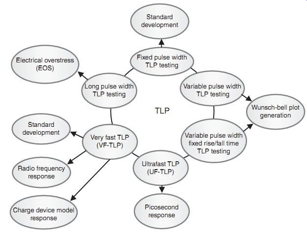
FIG. 1 Pulse testing: Standard development Fixed pulse width TLP testing
Long pulse width TLP testing Standard development Radio frequency response
Charge device model response Very fast TLP (VF-TLP) Ultrafast TLP (UF-TLP)
Picosecond response Variable pulse width fixed rise/fall time TLP testing
Variable pulse width; TLP testing Wunsch-bell plot generation TLP Electrical
overstress (EOS)
---------------
2. Scope
The scope of the TLP ESD test is for the testing, evaluation, and classification of components and micro- to nano-electronic circuitry. The test is to quantify the sensitivity or susceptibility of these components to damage or degradation to the defined TLP test.
3. Purpose
The purpose of the TLP ESD test is for establishment of a test methodology to evaluate the repeatability and reproducibility of components to a defined pulse event in order to classify or compare ESD sensitivity levels of components.
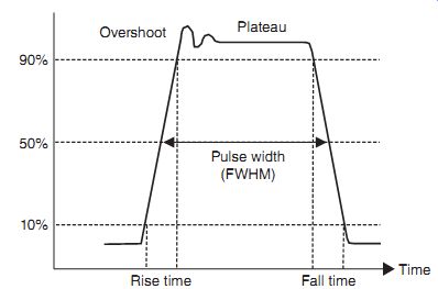
FIG. 2 Transmission line pulse (TLP) waveform
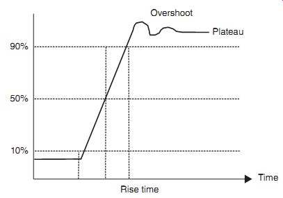
FIG. 3 Transmission line pulse waveform (expansion)
4. Pulse Waveform
TLP testing provides a square pulse from the TLP source. The TLP test system source can provide different pulse widths, rise times, and fall times. For the semiconductor industry, the TLP standard was developed with a fixed pulse width for comparison of TLP testing results.
The TLP results change with different pulse characteristics.
FIG. 2 shows the TLP pulse waveform characteristics. FIG. 3 shows the TLP pulse waveform expanded view to highlight the characteristics at the front end of the pulse-waveform.
The waveform characteristic can be defined by specific parameters:
• Pulse plateau
• Pulse width
• Rise time
• Fall time
• Maximum peak current overshoot
• Maximum current ringing duration
• Maximum peak voltage overshoot
• Maximum voltage ringing duration
• Measurement window.
Pulse plateau: The plateau of the pulse is the maximum value in the measurement window. The plateau is a time-averaged value after the overshoot and the oscillation region.
Pulse width: The pulse width is defined as the full width half maximum (FWHM). This is measured at 50% magnitude. For the TLP standard, this is defined as 100 ns. The reason with this pulse width is to make the energy under the TLP waveform equivalent to the energy of the HBM waveform.
Rise time: The rise time is defined as the time it takes to rise from 10% to 90% of the pulse plateau. For the TLP standard, the rise time of 10 ns is used.
Fall time: The fall time is defined as the time it takes to fall from 90% to 10% of the pulse plateau. For the TLP standard, the fall time is equal to or greater than the rise time. For the TLP standard, the fall time of 10 ns or greater is used.
Maximum peak current overshoot: The maximum peak current overshoot is defined as the magnitude of the overshoot peak current above the current plateau. The TLP standard states that this should be less than 20% of the plateau current. This is defined into a short circuit.
Maximum current ringing duration: The maximum current ringing duration is defined as the length of time between the beginning of the current pulse and the time that the ringing reaches less than 5% of the plateau current. For the TLP standard, the maximum current ringing duration should be less than 25% of the pulse width.
Maximum peak voltage overshoot: The maximum peak voltage overshoot is defined as the magnitude of the overshoot peak voltage above the voltage plateau. The TLP standard states that this should be less than 20% of the plateau voltage. This is defined into an open circuit.
Maximum voltage ringing duration: The maximum voltage ringing duration is defined as the length of time between the first overshoot beyond the plateau voltage to the time it reaches 5% of the plateau voltage. For the TLP standard, the maximum voltage ringing duration should be less than 25% of the pulse width.
Measurement window: The measurement window is the range of time within the pulse width where the voltage and current can be measured and extracted in the plateau. According to the TLP standard, the measurement window should be greater than 10% of the TLP pulse width.
5. Equivalent Circuit
For the TLP test system, an equivalent model circuit representation can be defined. The TLP circuit is a transmission line (TL) source. The TLP source does not demonstrate any resistive loss and hence can be represented as a lossless inductor-capacitor (LC) transmission line (FIG. 4). FIG. 4 shows two representations of the equivalent circuit.
6. Test Equipment
TLP test systems can be used in different test configurations. The TLP test system can be in a configuration defined as a current source, TDR, TDT, and TDRT configuration (Figures 5.5-5.8, respectively).
There are requirements for the equipment independent of the test configuration. The equipment utilized for a TLP test system includes the following:
• Oscilloscope
• Voltage probe
• Current probe
• Transmission line
• High-voltage power supply
• High-voltage switch
• Attenuator
• Rise time filter.
There are requirements for the equipment in the TLP system. For all the equipment, the equipment must be able to withstand the current and voltage levels without electrical damage.
The oscilloscope must have a single shot bandwidth of at least 200MHz. The voltage and current probes must have a minimum bandwidth of 200MHz.
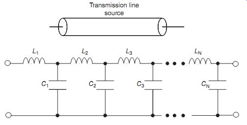
FIG. 4 Transmission line pulse (TLP) equivalent circuit
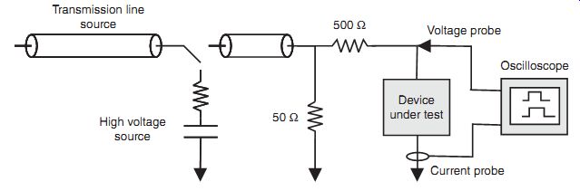
FIG. 5 Transmission line pulse (TLP) current source configuration
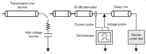
FIG. 6 Transmission line pulse (TLP) time domain reflectometry (TDR)
configuration
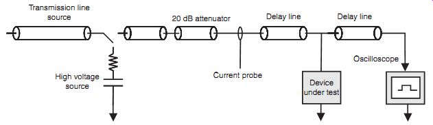
FIG. 7 Transmission line pulse (TLP) time domain transmission (TDT)
configuration
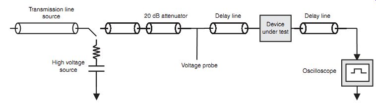
FIG. 8 Transmission line pulse (TLP) time domain reflection transmission
(TDRT) configuration
6.1 Current Source
TLP test system method is known as the current source TLP (FIG. 5). The current source TLP method comprises the following test equipment:
• High-voltage charging source
• High-voltage charging source series resistor
• A transmission line for matching (50-Ohm)
• A transmission line switch
• A transmission line source
• A 56-O ground termination
• A 500-O series resistor
• A current probe
• A voltage probe
• A two-channel oscilloscope.
In the current source TLP method, the components are arranged as shown in FIG. 5.
The high-voltage source charges the transmission line to a high voltage through the 10M-O resistor element. In this method, there is a 500-O resistor element in series with the DUT. There is also a termination resistor of 56-O. A two-channel oscilloscope has a voltage probe and a current probe that measures the voltage and current across the DUT.
6.2 Time Domain Reflection (TDR)
TLP test system method is known as the TDR TLP (FIG. 6). The TDR-TLP method comprises the following test equipment:
• High-voltage charging source
• High-voltage charging source series resistor
• A transmission line for matching (50-Ohm)
• A transmission line switch
• A transmission line source
• A transmission line connection
• A transmission line delay
• An attenuator
• A voltage probe
• A single-channel oscilloscope.
In the TDR-TLP method, the components are arranged as shown in FIG. 6. The TDR-TLP system is a 50-Ohm system. The high-voltage source charges the transmission line to a high voltage through the 10M-O resistor element. An attenuator is placed in series with the DUT. A single-channel oscilloscope is used with a voltage probe that measures the voltage across the DUT. A reference pulse is required if the reflected pulse overlaps the initial TLP pulse.
A TDR TLP system can also be formed using a balun (FIG. 6). The TDR-TLP method with a balun comprises the following test equipment:
• High-voltage charging source
• High-voltage charging source series resistor
• A 50-Ohm coaxial charge line
• A single-pole double-throw (SPDT) coaxial switch
• A 20 dB attenuator network
• A coaxial sensor
• A 50-Ohm transmission line connection cable
• A balun
• A set of probe needles.
6.3 Time Domain Transmission (TDT)
TLP test system method is known as the TDT TLP (FIG. 7). The TDT-TLP method comprises the following test equipment:
• High-voltage charging source
• High-voltage charging source series resistor (10 M-Ohm)
• A transmission line switch
• An attenuator
• A transmission line for matching
• A high impedance voltage probe
• A single-channel oscilloscope.
In the TDT-TLP method, the components are arranged as shown in FIG. 6. The TDR-TLP system is a 50-Ohm system. The high-voltage source charges the transmission line to a high voltage through the 10M-O resistor element. No attenuator is placed in series with the DUT. A single-channel oscilloscope is used with a voltage probe that measures the voltage across the DUT. A reference pulse is required.
6.4 Time Domain Reflection and Transmission (TDRT)
TLP test system method is known as the TDRT TLP (FIG. 8). The TDRT-TLP method comprises the following test equipment:
• High-voltage charging source
• High-voltage charging source series resistor (10-MO)
• A transmission line switch
• A transmission line connection
• An transmission line delay
• A transmission line termination
• A high impedance voltage probe
• A two-channel oscilloscope.
In the TDRT-TLP method, the components are arranged as shown in FIG. 8. The DUT is placed in a series configuration in the center of the system and allows for both reflection and transmission of the signal. The TDRT-TLP system is a 100O system. The high-voltage source charges the transmission line to a high voltage through the 10MO resistor element. No attenuator is placed in series with the DUT. A two-channel oscilloscope is used with a voltage probe that measures the voltage across the DUT. The transmitted current is used for measuring the current through the DUT. A reference pulse is required.
6.5 Commercial Transmission Line Pulse (TLP) Systems
In the early development of TLP testing, there was no commercial test equipment. FIG. 9 shows an example of the first commercial TLP system, the Barth Model 4002 TLP.
Prior to the Barth TLP Model 4002, many corporations were doing TLP testing internal to their corporation for technology characterization using "home grown" systems. The Barth 4002 TLP+ Pulse Curve Tracer characterizes the ESD robustness of silicon chip protection circuitry.
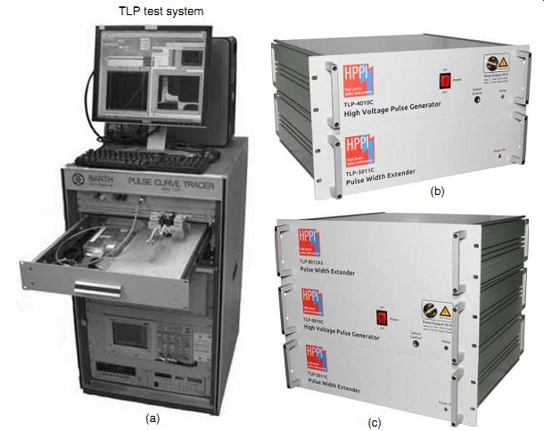
FIG. 9 (a) Transmission line pulse (TLP) commercial test equipment--Barth
system (Barth Electronics Inc.). (b) Transmission line pulse (TLP) commercial
test equipment--High power pulse instruments (HPPI) TLP 4010C/3011C (HPPI
GmBH). (c)HPPI TLP-8012/8010C/3051C Pulse Width Extender (HPPI GmBH)
The Barth Model 4002 TLP system components comprise the following:
• Barth 40021 control box/pulse generator
• Tektronix 500MHz two-channel digitizing oscilloscope
• Keithley Pico-ammeter/voltage source
• Stanford Research Systems high-voltage power supply
• Barth 44001A-48 DIP Test Fixture
• A computer
• High-resolution monitor
• Color printer.
Programmed rectangular pulses are applied to the DUT during the testing process. A leakage current measurement is made after each pulse to obtain the leakage evolution current as a function of the TLP pulse voltage.
In this test system, packaged or wafer level testing is possible. A dual wafer probe (Barth Model 45002WP) allows for wafer level testing. The Barth 45002WP Dual Wafer Probe has two separate needles and isolated probe connections that can be independently positioned. To avoid mechanical issues of crossed needles, a constant impedance-reversing switch allows for reversal of the TLP pulse polarity.
The need to retain 50-Ohm impedance avoids reflections and measurement errors. A controlled 50-Ohm impedance minimizes the influence on the parasitic on the measurement. For both the packaged device socket and the wafer level system, a 50-Ohm controlled impedance exists for the packaged socket and the Barth TLP wafer prober. The Barth TLP probe station also has a controlled 50-Ohm impedance throughout its connections to the two needle contacts at any two pads. From an inherently low 50-Ohm source impedance, a test pulse without ringing, undershoot, or overshoot, or pulse distortion can be formed.
The TLP test system has a manually selectable pulse width of 75-150 ns. The TLP pulse voltage can range from 0 to 250V, with a TLP pulse current to 5A for a 50-Ohm load, and 10A for a short circuit. The 10-90% TLP pulse rise time can be varied from 0.2, 2, and 10 ns. The system can provide up to 10 test pulses per minute. The leakage voltage can be varied from 0 to 100V and can vary from picoamps to 2.5mA.
FIG. 9(b) shows an example of a commercial benchtop TLP system that provides the capability to test multiple ESD tests in a common test system. The HPPI TLP test system TLP-4010C/3011C provides both wafer and packaged testing. The test system has two basic configurations. The first configuration is the TLP 4010C high-voltage pulse generator unit, and the second configuration is the TLP 4010C combined with the TLP-3011C pulse width extender. This test system is a 50-Ohm impedance system avoiding ringing and allowing for fast rise times without ringing. The TLP-4010C includes printed circuit board (PCB) adapter, current sensors, 18GHz DUT switch, and cable connections.
The TLP 4010C has eight programmable pulse widths from 1 to 100 ns, allowing for evaluation of the power-to-failure over a wider range from the standard TLP test (e.g., 100 ns) to shorter pulse widths. This explores the response of electronics from the HBM to CDM pulse time regime [39].
The TLP 3011C pulse width extender can extend the pulse width well into the microsecond regime. The TLP 3011C allows for extension of the pulse into 1.6 µs.
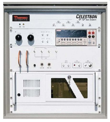
FIG. 10 Transmission line pulse (TLP) commercial test equipment--Thermo
KeyTek Bench Top Celestron Flexible Bench Top TLP/VF-TLP System (Thermo Fisher
Scientific)
FIG. 10 shows an example of a commercial benchtop TLP system that provides the capability to test multiple ESD tests in a common test system. The Thermo Scientific Celestron Flexible Bench Top TLP/VF-TLP System can provide both the TLP event and the very fast transmission line pulse (VF-TLP) event [40]. In addition, this test system can provide testing of HBM and machine model (MM) at wafer level, or packaged level.
The test system can be configured in TDR-O, TDR-S, TDT, TDRT, and Hi-Z TDRT test modes. The system can provide a standard TLP pulse width of 100 ns, as well as a VF-TLP pulse duration of 10 ns [40].
During the testing procedure, the operator of the system can select a range of test stress voltages, pulse polarity, as well as leakage and curve tracing values. The operator is free to modify the measurement test window within the TLP pulse before or after the testing completion. This allows for reduction of the error in the testing measurement in extraction of the current and voltage values.
------------
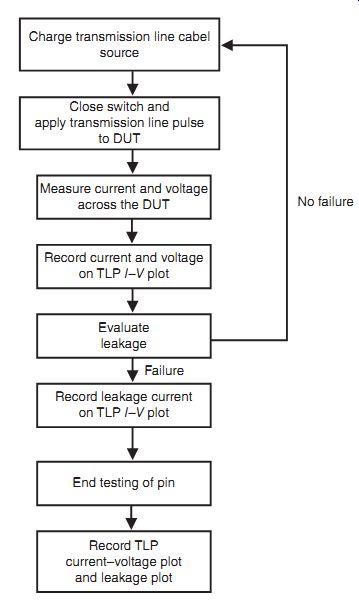
FIG. 11 TLP test procedure and sequence
Charge transmission line cable source Close switch and apply transmission line pulse to DUT No failure; Failure End testing of pin Record TLP current-voltage plot and leakage plot Evaluate leakage Record leakage current on TLP I-V plot Record current and voltage on TLP I-V plot Measure current and voltage across the DUT
-------------
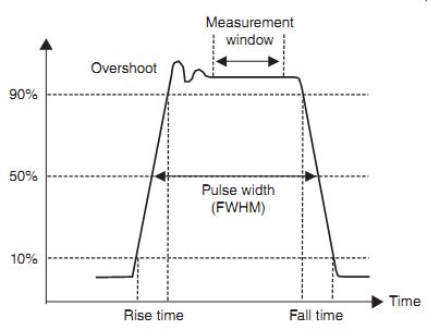
FIG. 12 TLP measurement window and the current overshoot
7. Test Sequence and Procedure
For the TLP testing, there is a test sequence and a procedure to provide the TLP pulsed current-voltage characteristic. The TLP test procedure uses a series of pulses with increasing pulse amplitude (FIG. 11). The steps in the procedure are as follows:
• Select a pulse of a given pulse width, rise time, fall time, amplitude, and polarity.
• Select a step size increment.
• Test a first component.
• Select a minimum time between successive steps (e.g., greater than 0.1 s).
• Define a failure criteria.
• Apply a stress pulse of fixed width to the DUT.
• Measure and record stress pulse voltage and current, representing one I-V point on the DUT of the I-V characteristic,
• Perform a post-stress evaluation of the DUT.
• If no "failure" occurs, the process is repeated with the next pulse applied at a higher magnitude; if failure occurs, the testing is stopped.
7.1 TLP Pulse Analysis
For the TLP testing methodology, TLP pulse event analysis is required. The TLP methodology must define a measurement window to extract current and voltage from the DUT.
7.2 Measurement Window
The TLP methodology must define a measurement window to extract current and voltage from the DUT. A measurement window is chosen within the pulse event that avoids the rise time, fall time, and the region of current and voltage overshoot, oscillation, and ringing (FIG. 12).
The measurement is taken in a quiescent region so that an accurate value for the voltage and current is obtained. This is achieved by sampling a number of points and averaging them.
The measurement time window is greater than 10% of the pulse width to allow for averaging of many data points. The measurement window is taken in the time outside of the overshoot region.
7.3 Measurement Analysis--TDR Voltage Waveform
In this section, the measurement analysis of a pulse waveform in a TDR TLP system is discussed. FIG. 13 illustrates a voltage characteristic for a measurement where the DUT is under 50-Ohm. In the plot, the incident pulse is shown, as well as the reflected pulse. In the center region, the incident and reflected pulses overlap in a subtractive fashion. The measurement window is shown in the region where the incident and reflected pulses overlap.
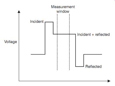
FIG. 13 TLP analysis--TDR voltage waveform
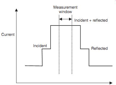
FIG. 14 TLP analysis--TDR current waveform
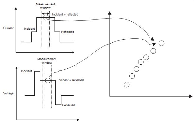
FIG. 15 TLP analysis--TDR results for current and voltage
7.4 Measurement Analysis--Time Domain Reflection (TDR) Current Waveform
In this section, the measurement analysis of a current pulse waveform in a TDR TLP system is discussed. FIG. 14 illustrates a current characteristic for a measurement where the DUT is under 50-Ohm. In the plot, the incident pulse is shown, as well as the reflected pulse. In the center region, the incident and reflected pulses overlap in an additive fashion. The measurement window is shown in the region where the incident and reflected pulses overlap.
7.5 Measurement Analysis--Time Domain Reflection (TDR) Current-Voltage Characteristic
In this section, the measurement analysis of a pulse waveform in a TDR TLP system are superimposed on the leakage characteristic plot is shown. FIG. 15 illustrates a voltage and current versus time characteristic for a measurement as well as the current-voltage (I-V) characteristic. The measurement for the voltage and the current is achieved by evaluating the average within the measurement window. These averaged values are then recorded in the I-V plot. In addition to the (I, V) point placed on the I-V plot, the leakage current post-stress is also recorded.
8. TLP Pulsed I-V Characteristic
From TLP testing, a pulsed current-voltage (I-V) characteristic can be constructed. Each data point in the pulsed I-V characteristic is the current and voltage across the DUT. Each data point represents a pulse in the test sequence. The voltage on the transmission line (TL) source is increased for each step in the I-V characteristic.
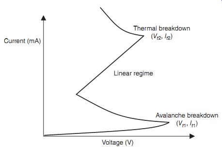
FIG. 16 Construction of transmission line pulse (TLP) I-V characteristic
FIG. 16 illustrates the current and voltage from a pulse event and how it is projected onto the current-voltage characteristic. Each current and voltage point is an average of the measured pulse event where the information is from an average of measurements from the measurement window.
8.1 TLP I-V Characteristic Key Parameters
The TLP I-V characteristics contain key metrics. The TLP I-V characteristic comprises the following key parameters:
• Avalanche voltage
• Trigger point
• Holding point
• Turn-on voltage
• On-resistance
• Clamping voltage
• Second trigger point
• Soft failure current
• Failure current.
8.2 TLP Power Versus Time
In the early development of TLP testing, the focus was not on the current and voltage I-V characteristics but on power. The primary reason: the researchers were interested in the power-to-failure. For the power analysis, the techniques were to evaluate the incident, transmitted, and reflected power as a function of time.
The first system developed by J.J. Whalen and H. Domingos was a pulse system in a TDRT configuration [4]. In this configuration, the measured parameters were the incident, transmit ted, and reflected power as a function of time. From this method, the absorbed power in the DUT was the incident power minus the reflected power and the transmitted power. Waveforms of the incident power, the reflected power, and the transmitted power as a function of time were recorded. In this methodology, the time-to-failure was observable from transitions in the power waveforms.
The energy-to-failure can be defined as
EA = EI
- ER--ET
where EI
is the incident energy, ER is the reflected energy, and ET is the transmitted energy.
8.3 TLP Power Versus Time--Measurement Analysis
A second test system, published in 1979, was simplified to include a single pulse unit, a square pulse matching network, a voltage probe, a current probe, and a dual-channel oscilloscope.
Note that this system is essentially the first TLP system published in the EOS/ESD Symposium proceedings.
In this system, the voltage across the device, current across the device, and the time-to-failure were used to calculate the energy at failure. The absorbed energy versus time-to-failure can be quantified.
The energy-to-failure, absorbed energy EA can be defined as
EA = V × I × TF
where V is the voltage across the DUT before failure, I is the current across the DUT before failure, and TF is the time duration before failure.
FIG. 17 shows the power versus time plot for a TDRT TLP system. The power versus time can be observed for the incident power, the reflected power, and the transmitted power.
8.4 TLP Power-to-Failure versus Pulse Width Plot
For construction of the Wunsch-Bell power-to-failure curve, a series of successive tests are made for different pulse widths. The Wunsch-Bell power-to-failure characteristics are formed by sweeping all possible pulse widths capable of the test system. During this test sequence, the rise time and fall time are made fixed. For each pulse width, a TLP pulsed I-V plot (for a given pulse width) is formed. From the test, the failure point (I-V current and voltage) is extracted. This failure point is the product of the current-to-failure (If ) and the voltage-to-failure (Vf ); this can be represented as the power-to-failure (Pf). The data is plotted as the power-to-failure (Pf ) versus the logarithm of the pulse width. FIG. 18 shows the test sequence.
For construction of the Wunsch-Bell power-to-failure curve, a series of test are made for different pulse-widths. The Wunsch-Bell power-to-failure characteristics are formed by sweeping all possible pulse widths capable of the test system (FIG. 19).
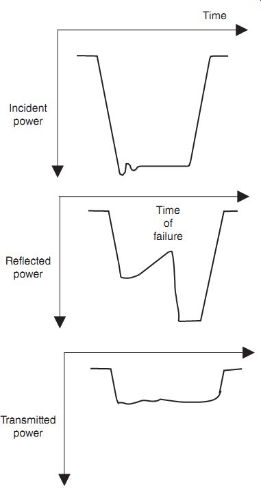
FIG. 17 Power versus time plot
9. Alternate Methods
Alternate methods will occur in the future. With increasing interest in EOS events, there is growth in the long pulse events. Long duration transmission line pulse (LD-TLP) events (e.g., also referred to as long pulse TLP (LPTLP) provide an understanding of the response of devices and circuits closer to the steady state regime [36].
9.1 Long Duration TLP (LD-TLP)
LD-TLP event waveforms are rectangular pulses with a long pulse width. The distinction between the TLP standard and the long pulse TLP events is the length of the pulse width.
FIG. 20 shows an example of the LD-TLP waveform. The defined LD-TLP pulse width is 500 ns.
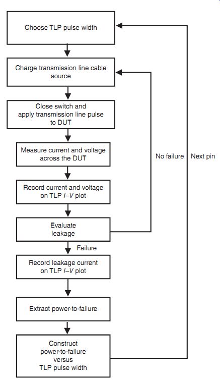
FIG. 18 Test sequence for Wunsch-Bell curve construction
9.2 Long Duration TLP Time Domain
The long duration TLP (LD-TLP) can be plotted on a Wunsch-Bell power-to-failure plot [36].
FIG. 21 is an example of the Wunsch-Bell plot highlighting the long-pulse TLP time domain. The LD-TLP pulse width is near the end of the thermal diffusion regime and/or steady state regime.
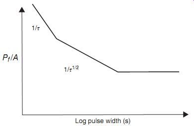
FIG. 19 Wunsch-Bell curves: power-to-failure versus pulse width
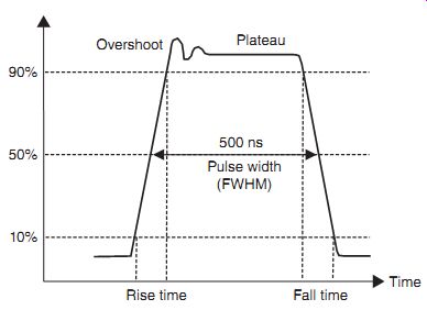
FIG. 20 Long-pulse TLP waveform
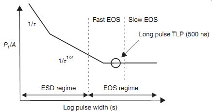
FIG. 21 Wunsch-Bell curve highlighting long duration TLP time domain
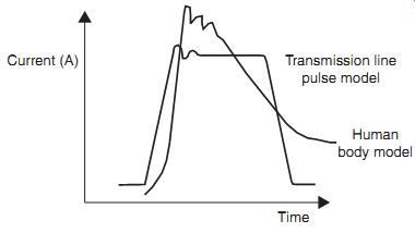
FIG. 22 Transmission line pulse (TLP) and HBM pulse waveform comparison
10. TLP-to-HBM Ratio
10.1 Comparison of Transmission Line Pulse (TLP) and Human Body Model (HBM) Pulse Width
The TLP can be compared to the HBM. The motivation is the interest of eliminating HBM testing and replace it with TLP testing only. A metric can be established between the TLP current-to-failure and the HBM failure voltage level. FIG. 22 shows a comparison of the HBM voltage level and TLP current-to-failure [41]. For example, this can be expressed as:
VHBM(V)= 1680ITLP(A).
11. Summary and Closing Comments
In this section, one of the most important tests in the history of ESD testing, the TLP model is discussed. This method had a rapid growth in popularity in the late 1990s due to its powerful value in semiconductor device and circuit development. The ability to see the current and voltage characteristics across the DUT was of significant value to ESD engineers, circuit designers, to failure analysis teams who need to develop, understand, or debug the response of devices and circuits. This was a large step forward in increasing the technical nature of ESD development.
In section 6, another important test in the history of ESD testing, the high-speed short-pulse version of the TLP model, known as the VF-TLP test, is discussed.
Exercises
1. An HBM test result quotes a number as a result, typically an ESD HBM level. A TLP test also describes some metrics from the TLP results. How does it differ? Where is the voltage or current measured in the case of an HBM result? Where is it measured for a TLP test?
2. What information does a TLP test provide that an HBM test does not provide?
3. Explain the differences between an HBM test and TLP procedure.
4. Explain the difference between the test sequence of an HBM test and a TLP test.
5. An HBM test is a multipin test, whereas the TLP test is a two-pin test. Explain how the tests are the same, and how they are different.
6. Show an example of a TLP I-V characteristic of a diode. Explain each region of a TLP I-V characteristic.
7. Show an example of a TLP I-V characteristic of an n-channel MOSFET. Explain each region of a TLP I-V characteristic.
8. Show an example of a TLP I-V characteristic of a p-channel MOSFET. Explain each region of a TLP I-V characteristic. How does the p-channel MOSFET TLP I-V characteristic differ from the n-channel MOSFET TLP I-V characteristic?
9. Show an example of a TLP I-V characteristic of a bipolar transistor. Explain each region of a TLP I-V characteristic. How does it differ from an n-channel MOSFET?
10. Show an example of a TLP I-V characteristic of a silicon controlled rectifier. Explain each region of a TLP I-V characteristic. How does it differ from an n-channel MOSFET? How does it differ from a bipolar transistor?
11. Show an example of a TLP I-V characteristic of an n-well ballast resistor. Explain each region of a TLP I-V characteristic. How does it differ from an n-channel MOSFET? How does it differ from a bipolar transistor?