AMAZON multi-meters discounts AMAZON oscilloscope discounts
1. History
Electrostatic discharge (ESD) events can impact electronic and electrical systems in assembly, shipping, installation, and post-installation. Systems, subsystems, and peripherals can be involved in ESD events that can include destructive and nondestructive events. Environmental conditions, such as low humidity, can influence electronic systems. In addition, installation and assembly conditions also can influence the sensitivity, susceptibility, and vulnerability to ESD events. ESD immunity requirements and test methods for electrical and electronic equipments subjected to ESDs from operators and personnel are necessary in today's electronic systems.
2. Scope
The scope of the IEC 61000-4-2 ESD test is for the testing, evaluation, and classification of systems [1]. The test is to quantify the sensitivity or susceptibility of these components to damage or degradation to the defined IEC 61000-4-2 test [1-32]. This includes ESD immunity requirements and test methods for electrical and electronic equipments subjected to ESDs from operators and personnel. The IEC 61000-4-2 test defines test level ranges that relate to environmental and installation conditions.
3. Purpose
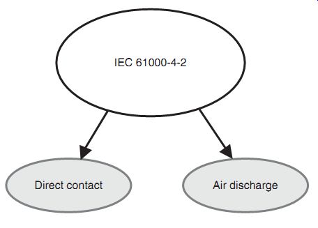
FIG. 1 IEC 61000-4-2
The purpose of the IEC 61000-4-2 ESD test is for establishment of a test methodology to evaluate the repeatability and reproducibility of systems to a defined pulse event in order to classify or compare ESD sensitivity levels of systems [1]. The purpose of the IEC 61000-4-2 test is to establish a common and reproducible basis for evaluation of electronic and electrical systems to ESD events. The IEC 61000-4-2 test defines the following (FIG. 1) [1]:
• Pulse waveform
• Range of test levels
• Test equipment
• Test setup and configuration
• Test procedure
• Test calibration.
3.1 Air Discharge
The IEC 61000-4-2 ESD test addresses air discharge events [1, 2]. The event involves the current arc discharge event between a metal tip and the system under test. In this case, the energy of the electromagnetic (EM) fields introduces electromagnetic interference (EMI) that can couple to the system. The test quantifies the sensitivity or susceptibility of the system to disturbs, upsets, or failure.
3.2 Direct Contact Discharge
The IEC 61000-4-2 ESD test also addresses direct contact discharge events [1-6]. In this case, direct contact is made with the system prior to initiation of the pulse event. In this case, the current of the IEC 61000-4-2 event is applied to any location in the system. The test quantifies the sensitivity or susceptibility of the system to disturbs, upsets, or failure.
4. Pulse Waveform
The IEC 61000-4-2 ESD is a well-defined pulse waveform. The waveform is defined by the ESD gun specifically designed to provide this pulse event to mimic the ESD event from a human body or metal object with a built-up static charge [1].
FIG. 2 illustrates an IEC 61000-4-2 event [1]. The event consists of a fast high current event followed by a second slower event. The fast event has a rise time of 0.7-1 ns. The slower event has a lower current with a peak at 30 ns and a decay time of 60 ns. The energy accumulation capacity is associated with a 150 pF capacitor. The discharge resistance is a 330O resistor.
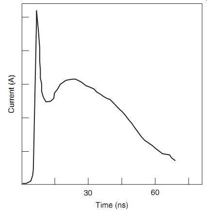
FIG. 2 IEC 61000-4-2 pulse waveform
This provides an 8 kV event for direct contact resistance and 15 kV event for air discharge. The polarity of the pulse event addresses positive and negative events.
4.1 Pulse Waveform Equation
For the IEC 61000-4-2 pulse waveform, an analytical formulation was established by Heidler [31, 32]. The Heidler formulation can be expressed as two exponential terms as follows:
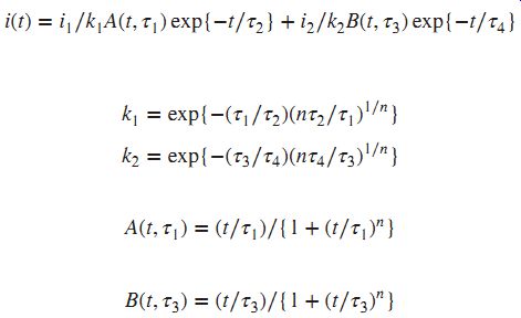
In this formulation, the variable i1 and i2 are currents in amperes, ?1, ?2, ?3, and ?4 are time constants in nanoseconds, and n is a constant [31, 32]. An example of parameters, for a 2 kV positive pulse, i1 =3.6A, and i2 =3.74A, ?1 =0.29, ?2 =18.44, ?3 =34.34, and ?4 =31.02 (in nanoseconds), and n=3.26 [31, 32].
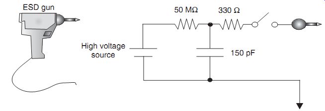
FIG. 3
IEC 61000-4-2 ESD gun equivalent circuit (Thermo Fisher Scientific)
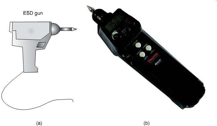
FIG. 4 (a) IEC 61000-4-2 commercial test equipment--ESD gun. (b) IEC
61000-4-2 MiniZap ESD simulator--Thermo KeyTek (Thermo Fisher Scientific)
5. Equivalent Circuit
FIG. 3 shows the equivalent circuit schematic for the IEC 61000-4-2 [1]. The circuit schematic shows a 150 pF capacitor and a 330 Ohm resistor. The charging resistance is a 50-100 M-Ohm source. This provides an 8 kV event for direct contact resistance and 15 kV event for air discharge. The polarity of the pulse event addresses both positive and negative events.
6. Test Equipment
An example of a commercial test simulator is shown in FIG. 4(a). This ESD simulator is a handheld ESD gun with a metal tip allowing for easy access to test systems. Many different vendors have produced ESD guns for evaluation of manufacturing environments.
An example of a commercial test simulator is shown in FIG. 4(b). This ESD simulator is a handheld ESD gun with a metal tip allowing for easy access to test systems, subsystems, and assemblies. FIG. 4(b) is the Thermo Scientific MiniZap-15 ESD Simulator [33]. The MiniZap-15 Simulator supports testing to the international standard IEC/EN 61000-4-2 and ANSI C63.16. The tester is suitable for 8 kV contact mode discharge and 16 kV air discharge testing. This simulator generates "real-world" ESD pulses, which are repeatable. It has both E-field and H-field diagnostics and suitable for vertical coupling plane (VCP) and horizontal coupling plane (HCP) for indirect ESD testing. The MiniZap tester does not use a voltage multiplier. As a result, it will not introduce testing errors and uncertainties. Additional ESD test standards can be done with the simulator, by changing of the plug-in tips.
6.1 Test Configuration
In the IEC 61000-4-2 test specification, the table configuration and grounding condition are specified [1]. This is significantly different from the human body model (HBM) component ESD test specification.
Using a table top for testing, a horizontal metal coupling plane is used below an insulation sheet (FIG. 5). The HCP is connected to a ground reference plane on the floor using a 2 × 470 kO bleed resistor cable. This is acceptable when the equipment under test (EUT) can be placed on the table top. Given that the EUT does not it on the table, and the system is placed on an insulation pallet whose dimension is greater than 0.1m high.
For indirect contact discharge events, a VCP should be placed 10 cm from the EUT. The VCP should also be connected to the ground reference using the 2 × 470 kO bleed resistor cable [1].
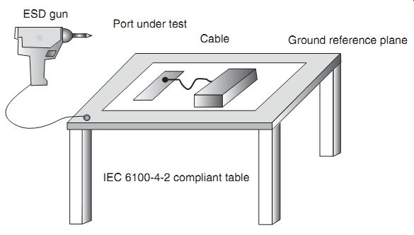
FIG. 5 IEC 61000-4-2 test equipment--table configuration
6.2 ESD Guns
To perform the IEC 61000-4-2, there are ESD guns to apply the ESD event to the component or system. In the following sections, modules exist for system level testing.
6.3 ESD Guns--Standard Versus Discharge Module
For the IEC 61000-4-2 standard, there is a module for the gun that is specified. But there are many discharge modules, equivalent circuit schematic for the IEC 61000-4-2. The IEC 61000-4-2 standard defines a 150 pF capacitor and a 330Oresistor [1]. The charging resistance is a 50-100MO source. This provides an 8 kV event for direct contact resistance and 15 kV event for air discharge. There are additional discharge modules that can be substituted into test systems to provide the equivalent test.
6.4 Human Body Model Versus IEC 61000-4-2
In FIG. 6, the HBM and the IEC 61000-4-2 waveform are illustrated. There are a few distinct differences between the two waveforms. The HBM waveform is a double exponential waveform of single polarity. The HBM waveform includes an RC network from the 1500O resistor and 100 pF capacitor. For the IEC 61000-4-2 standard, there is also an RC network contained within the ESD gun, but with different resistor and capacitor values. A second key feature that is present in the IEC 61000-4-2 waveform is the rapid peak at the beginning of the waveform. The fast peak of an IEC 61000-4-2 waveform is associated with the charge present at the tip of the ESD gun [8, 12, 13].
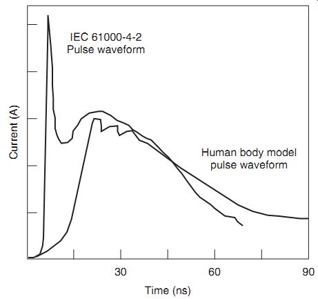
FIG. 6 IEC 61000-4-2 versus HBM waveform comparison
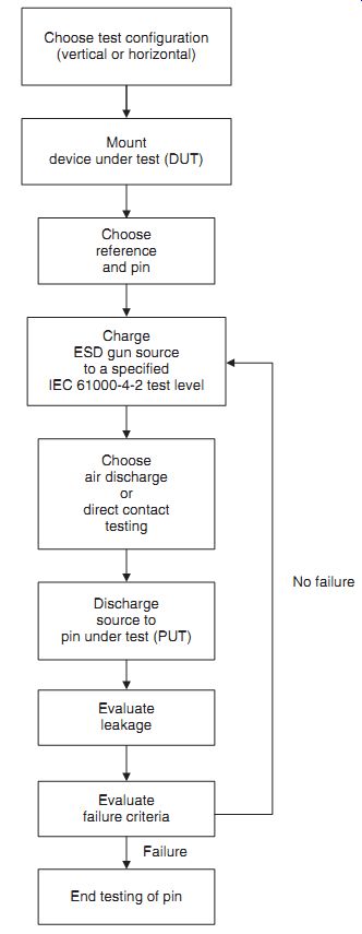
FIG. 7 IEC 61000-4-2 test procedure
7. Test Sequence and Procedure
The test procedure and test sequence for the IEC 61000-4-2 event is a simple test procedure (FIG. 7). First, the environment for the room must be between 15 and 35 °C. The room relative humidity (RH) must be between an RH level of 30-60% [1].
For direct discharge events, the ESD gun is to be placed to the location of the system under test. The ESD gun is then discharged at 1 s intervals. The test is to be performed for both polarities and repeated at least 10 times. The results of the test are then recorded.
For indirect discharge events, the ESD gun is to be discharged to the horizontal and VCPs instead of directly to the EUT. The ESD gun is then discharged at 1 s intervals. The test is to be performed for both polarities and repeated at least 10 times. The results of the test are then recorded.
The recording of the test results can be classified based on the response. The response of the test can be defined as follows [1]:
• Normal operation within the operational specification of the system
• Loss of operation, loss of function, or temporary degradation that is recoverable by system self-recovery or "self-healing" function
• Loss of operation, loss of function, or temporary degradation that is nonrecoverable by sys tem self-recovery or "self-healing" function requiring operator intervention (e.g., power down, power up, or system reset)
• Loss of operation, loss of function, or nonrecoverable degradation that is nonrecoverable and damage to the system, components, software, or data.
8. Failure Mechanisms
FIG. 8 IEC 61000-4-2 induced failure mechanism
Failure mechanisms on a system level can be destructive and nondestructive events (FIG. 8). The following responses of the IEC 61000-4-2 test can be defined as failure mechanisms [1]:
• Loss of operation, loss of function, or temporary degradation that is recoverable by system self-recovery or "self-healing" function
• Loss of operation, loss of function, or temporary degradation that is nonrecoverable by sys tem self-recovery or "self-healing" function requiring operator intervention (e.g., power down, power up, or system reset)
• Loss of operation, loss of function, or nonrecoverable degradation that is nonrecoverable and damage to the system, components, software, or data
• Permanent damage to the components and system.
9. IEC 61000-4-2 ESD Current Paths
FIG. 9 is an example of an IEC 61000-4-2 ESD event applied to the ground rail VSS. The IEC 61000-4-2 current lows through the VSS ground rail. There are at least two paths for the current low. One path is through the ESD network to the signal pad. A second current path is through the ESD power clamp. The current through the ESD power clamp, as well as the ESD network, can low to the VDD power supply. The amount of current that lows to each is dependent on the resistance of the elements in the circuit. Current can also continue into the semiconductor chip through the ground rail [39, 44, 46, 48].
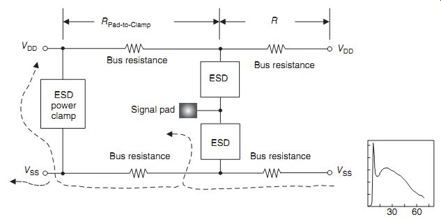
FIG. 9 IEC 61000-4-2 ESD event current paths--VSS positive polarity
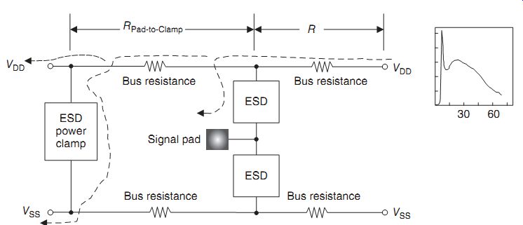
FIG. 10 IEC 61000-4-2 ESD event current paths
FIG. 10 is an example of an IEC 61000-4-2 ESD event applied to the power rail VDD. The IEC 61000-4-2 current lows through the VDD power rail. There are at least two paths for the current low. One path is through the ESD network to the signal pad. A second current path is into the VDD power bus and through the ESD power clamp. The current through the ESD power clamp, as well as the ESD network, can low to the VSS ground rail and into the VDD power supply. The amount of current that lows to each is dependent on the resistance of the bus resistance and the ESD power clamp resistance. Current can also continue into the semiconductor chip through the power supply rail or the ground rail. The IEC 61000-4-2 current lowing into the I/O and core can lead to ESD failures [39, 44, 46].
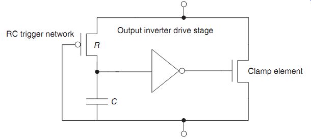
FIG. 11 IEC 61000-4-2 ESD protection power clamp
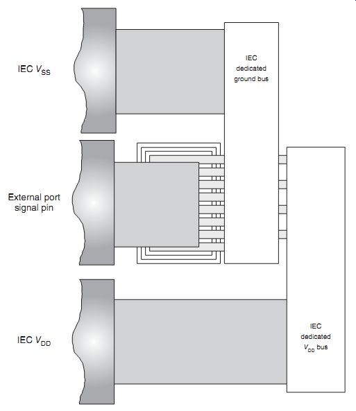
FIG. 12 IEC 61000-4-2 ESD protection circuits
10. ESD Protection Circuitry Solutions
One of the issues with the IEC 61000-4-2 ESD event is that ESD circuitry designed for HBM and MM events are not responsive to this ESD pulse event [37-47]. As a result, some of the circuitry must be modified due to the faster event. FIG. 11 shows an example of a solution to address the fast pulse portion of the IEC 61000-4-2 event. The standard circuit for the HBM and MM events used an inverter drive stage of three successive inverter stages to drive the gate of the output MOSFET between VDD and VSS power rails. Each complementary-metal oxide semi conductor (CMOS) inverter stage has a switching delay time. In order to make the circuit more responsive, the three CMOS stages were reduced to a single CMOS inverter stage [39, 44].
An ESD protection solution to avoid failures from the IEC 61000-4-2 ESD event is to establish separate IEC dedicated power rails. The high current pulse can lead to damage of the internal circuitry, as well as the power buses. If the resistance of the internal power bus is significantly higher than the IEC dedicated bus, then the residual current lowing into the semi conductor chip internal circuits will be minimized. FIG. 12 illustrates an example layout of an IEC bond pad, IEC wide interconnects, and IEC dedicated power buses [39, 44].
FIG. 13 illustrates a circuit schematic of the IEC bond pad, IEC wide interconnects, and IEC dedicated power buses. The schematic highlights the distinction between the IEC bus resistance, the standard bus resistance, and the bond-pad-to-power-clamp resistance.
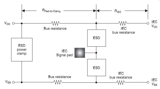
FIG. 13 IEC 61000-4-2 ESD event--power grid definition
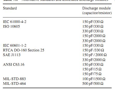
Table 1 Alternative standards and associated discharge modules
11. Alternative Test Methods
Alternative test requirements and methods for automotive, medical, avionics, and military equipment exist based on other system level standards [34-36]. Table 1 shows a listing of some alternate standard discharge modules. In many cases, the IEC 61000-4-2 waveform are used but with other requirements. In these alternative test standards, the resistor and capacitor elements of the discharge module vary. To test these other standards, different ESD guns with different modules are required.
11.1 Automotive ESD Standards
The automotive industry uses the ISO 10605:2008 standard [34]. This standard uses for different RC networks for the ESD gun source as shown in Table 1. In these tests, the initial peak remains the same, but the waveform differs due to the different RC decay.
In all cases, the test setup is the same. A distinction between the IEC 61000-4-2 test and the ISO 10605 test is the ISO test requires an insulating support above the HCP of 2-3mm, and be able to support a 25 kV event without electrical breakdown. Both standards have a 2-15 kV contact mode discharge, but the ISO 10605 standard requires an air discharge simulator event that can test to a 25 kV test level. Also note that the IEC test requires a repetition rate of 20 discharges per second, whereas the ISO standard only requires 10 discharges per second.
The automotive standard also requires a different failure criterion with a different function performance status classification (FPSC). The FPSC includes the following classifications [34]:
• Status I: The function performs as designed, during and after test.
• Status IFI: The function does not perform as designed during the test but returns automatically to normal operation after the test.
• Status IFII: The function does not perform as designed during the test and does not return automatically to normal operation after the test without intervention.
• Status IV: The function does not perform as designed during the test and cannot be returned to proper operation without more extensive intervention. The function shall not have sustained any permanent damage as a result of the testing.
11.2 Medical ESD Standards
In the medical industry, the standard that is used is IEC 60601-1-2 Edition 4.0 [35]. The ESD testing is equivalent to IEC 61000-4-2. For the medical industry, some unique features are added:
• Guidance for immunity test level for special environments
• Harmonization with risk concepts for safety and essential performance
• Specification of immunity testing and test levels associated with medical equipment ports and medical electrical systems.
The IEC requirement for medical equipment requires both contact and air discharge events.
The ESD test levels for air discharge are 2, 4, and 8 kV. The ESD test levels for contact discharge are 2, 4, and 6 kV.
The failure criterion for medical equipment are different from standard electronic equipment. These include the following [35]:
• False alarms
• Cessation or interruption of any operation
• Changes in operational mode
• Changes in programmable parameters
• Reset to factory defaults
• Initiation of any unintended operation
• Noise on a waveform that is indistinguishable from physiological produced signal
• Distortion of an image that is indistinguishable from physiological produced signal
• Failure of components
• Failure of automatic diagnosis.
11.3 Avionic ESD Standard
The avionic standard for ESD testing is RTCA DO-160 Section 25 [36]. This standard uses the IEC 61000-4-2 test waveform but only addresses the air discharge event. The test requires 10 positive discharge events and 10 negative discharge events at a level of 15 kV.
11.4 Military-Related ESD Standard
There are additional military standards for ESD of parts, assemblies, and equipment. These include the following:
• MIL-HDBK-263B: ESD Control Handbook for Protection of Electrical and Electronic Parts, Assemblies, and Equipment
• MIL-STD-1686: ESD Control Program for Protection of Electrical and Electronic Parts, Assemblies, and Equipment
• MIL-STD-785: Reliability Program for Systems and Equipment Development and Production.
12. Summary and Closing Comments
This section addressed system level concerns in semiconductor development known as IEC 61000-4-2. This test introduces a fast transient followed by a slower HBM-like waveform.
With the growing interest in system level electrical overstress (EOS), the interest in this test has emerged recently in semiconductor chip suppliers to test equipment. The section addressed the purpose, the scope, to the pulse waveform. ESD protection concepts for the IEC 61000-4-2 were also discussed.
Section 8 addresses a new semiconductor chip level test to address IEC 61000-4-2 pulse events into external ports of a semiconductor chip. This test is known as the human metal model (HMM). This test also introduces a fast transient followed by a slower HBM-like waveform that is only applied to specific ports exposed on a system level. With the growing interest in system level EOS, the interest in this test has emerged recently due to the request of system level developer for the semiconductor chip suppliers.
Problems
1. The IEC 61000-4-2 can be an air discharge event. What parameter variables influence the pulse waveform when it is an air discharge event?
2. The IEC 61000-4-2 discharge for an air discharge initiated an E- and H-field outside of the electronic system. Estimate the energy in the E-field and the H-field assuming a given current pulse of current I.
3. An ESD gun can be used to initiate a discharge to a semiconductor DRAM pin. What factors influence the discharge event?
4. An ESD gun can be used to initiate a discharge to a cell phone that contains external port for charging of the cell phone. What factors influence the discharge event?
5. An ESD gun can be used to initiate a discharge to a laptop. What are the potential sources of system failures? Assume the discharge is to the laptop USB ports. What factors influence the discharge event?
6. An ESD gun is used to zap an antennae of a cell phone. The cell phone is electrically connected to a gallium arsenide (GaAs) bipolar transistor power amplifier. Show the ESD event. What ESD protection circuitry can be used to avoid failure of the GaAs cell phone power amplifier?
7. Compare the IEC 61000-4-2 for a direct contact versus air discharge event. What is the influence on the fast current "peak"? How do the two waveforms differ?
References
[not listed]