AMAZON multi-meters discounts AMAZON oscilloscope discounts
1. History
In this section, the focus is on the transient surge phenomena, associated with the standard IEC 61000-4-5 Electromagnetic Compatibility (EMC)--Part 4-5: Testing and Measurement Techniques--Surge Immunity Test standard [1].
Transient surges, switching, and lightning-induced transients have been known to introduce failure of components and systems due to electrical overvoltage (EOV). A test method was needed to find the reaction of the equipment under test (EUT) from transients and lightning surges [2-23]. Transient surges occur on AC power mains as a result of switching operations.
Lightning strikes also induce transients to the power distribution systems or electrical ground.
Electrical surges also lead to inductive and capacitive coupling into signal lines (e.g., I/O lines) that can lead to EOV. As a result, surge test standards are required to evaluate transient surges (FIG. 1).
Electrical power lines are subjected to transient events from switching and lightning. Power system transient events can include major power system switching from capacitor banks. Load changes in the power distribution system can also introduce power transients. Power system disruption can also occur from system faults. System faults can include short circuits, and arcing during installation or operation.
Lightning can lead to transient surge. These include direct lightning and indirect events.
Direct lightning events can strike outdoor electronics or systems that introduce high currents (e.g., electrical overcurrent (EOC)) and EOV. Direct lightning events also introduce lightning ground currents. A direct lightning discharge to earth can couple into the ground path of a grounding system. In addition, electromagnetic (EM) emissions from lightning local to systems can induce electrical voltage and currents on conductors inside or outside of buildings.
Even the lightning protection devices can lead to electromagnetic interference (EMI) in adjacent systems.
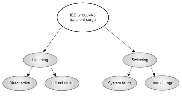
FIG. 1 IEC 61000-4-5
For evaluation of electrical overstress (EOS), standard has been developed for "surge testing" [1]. A standard that is being utilized presently for evaluation of components or populated printed circuit boards is the IEC 61000-4-5 EMC--Part 4-5: Testing and Measurement Techniques--Surge Immunity Test standard [1].
2. Scope
The scope of the IEC 61000-4-5 electrostatic discharge test is for the testing, evaluation, and classification of systems to transient surge and lightning. The test is to quantify the sensitivity or susceptibility of these components to damage or degradation to the defined IEC 61000-4-5 test [1].
3. Purpose
The purpose of the IEC 61000-4-5 transient surge test is for establishment of a test methodology to evaluate the repeatability and reproducibility of systems to a defined transient pulse surge event in order to classify or compare ESD sensitivity levels of systems. The purpose of the IEC 61000-4-5 test is to establish a common and reproducible basis for evaluation of electronic and electrical systems to transient surge events. The test method describes a consistent method to assess the immunity of equipment or systems. The IEC 61000-4-5 test defines the following (FIG. 1) [1]:
• Pulse waveform
• Range of test levels
• Test equipment
• Test setup and configuration
• Test procedure
• Test calibration.
4. Pulse Waveform
FIG. 2 shows the IEC 61000-4-5 surge test pulse open-circuit waveform. This pulse wave form is nonoscillatory for an open circuit. A surge generator is used that delivers a 1.2 µs rise time and a 50 µs full width half maximum voltage waveform [1].
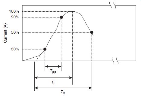
FIG. 2 IEC 61000-4-5 surge test pulse open-circuit waveform
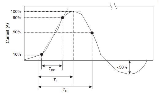
FIG. 3 IEC 61000-4-5 surge test pulse short-circuit waveform
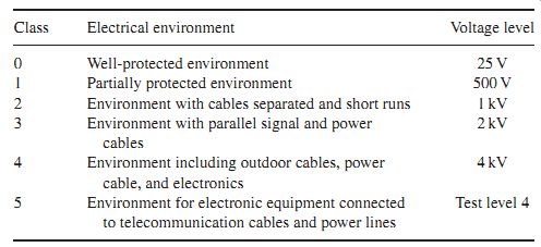
Table 1 IEC 61000-4-5 class and voltage levels
FIG. 3 shows the IEC 61000-4-5 surge test pulse short circuit waveform. This pulse waveform undergoes a negative transition after the first peak. A surge generator is used that delivers an 8 µs rise time and a 20 µs full width half maximum voltage waveform [1].
Table 1 illustrates the classes and associated voltage levels. In the table, the electrical environment is also highlighted for each class and voltage level.
5. Equivalent Circuit
FIG. 4 shows the IEC 61000-4-5 surge generator equivalent circuit. The surge generator is known as a combination wave generator [1].
6. Test Equipment
Commercial test equipment exists to support the IEC 61000-4-5 specification. Test equipment includes the Haefely AXOS 8 EMC immunity test system, Haefely PSURGE 8000 8 kV surge system, TeseqNSG3060 6 kV surge generator, and Thermo KeyTek ECAT 10 kV surge genera tor [23-26]. FIG. 5(a) and (b) is an example of a present-day test system for IEC 61000-4-5 transient surge testing.
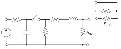
FIG. 4 IEC 61000-4-5 equivalent circuit of a transient surge generator
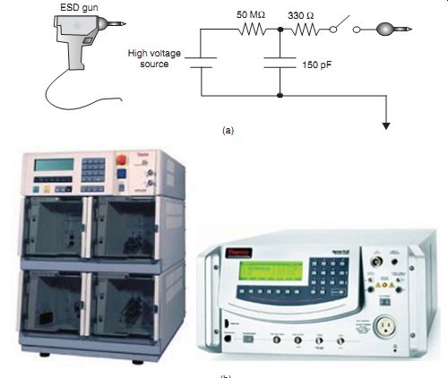
FIG. 5 (a) IEC 61000-4-5 high voltage transient surge commercial test
equipment. (b) IEC 61000-4-5 high voltage transient surge commercial test
equipment—EMC Pro Plus EMC Test System (Thermo
Fisher Scientific)
An example of a test system, the Thermo KeyTek ECAT 10 kV surge generator (i.e., com pliant with the IEC 61000-4-5 specification) can generate a voltage waveform of 1.2 µs rise time and a 50 µs full width half maximum voltage waveform. The peak voltage can achieve 250V to 6.6 kV in a 12-Ohm mode of operation. The peak current of 125A to 3.3 kA can be sourced. The repetition rate of these test systems can provide multiple pulses in a minute (e.g., maximum of four pulses in 1min). For an open-circuit voltage, a voltage waveform of 1.2 µs rise time and a 50 µs duration, and a 30% undershoot.
A second test system used for pre-compliance, quality assurance, and certification is the EMC Pro Plus EMC test system that satisfies the IEC 61000-4-5 standard [27]. This test system is the only test system capable of monitoring the IEC 61000-4-5 surge voltage and current at the output terminals; measurement at the generator can lead to large measurement errors. The system allows for surge testing to the IEC 61000-4-5 6 kV limit with combination, telecom, and ring waves. The combination wave surge requirement for 1.2/5 µs, the telecom wave surge requirement (10/700ms), and the ring oscillatory requirement can be fulfilled with the test system [27].
7. Test Sequence and Procedure
The recording of the test results can be classified based on the response (FIG. 6). The response of the test can be defined as follows [1]:
• Normal operation within the operational specification of the system
• Loss of operation, loss of function, or temporary degradation that is recoverable by system self-recovery or "self-healing" function
• Loss of operation, loss of function, or temporary degradation that is nonrecoverable by sys tem self-recovery or "self-healing" function requiring operator intervention (e.g., power down, power up, or system reset)
• Loss of operation, loss of function, or nonrecoverable degradation that is nonrecoverable and damage to the system, components, software, or data.
The IEC 61000-4-5 standard is required to be performed according to the manufacturer test plans. In the test, the following items are specified [1]:
• Surge generator
• Current transformer for waveform verification
• Digital or storage oscilloscope with 100MHz bandwidth
• Surge generator source impedance
• Repetition rate
• Sequence of application of the surge
• Installation
• Operation condition of EUT
• Number of tests
• Test levels
• Polarity
• Input and outputs tested
• Phase angle of coupling to alternating current (AC) mains
• Internal or external trigger.
Waveform verification is also required periodically. High voltage differential surge probes are needed for verification of the open-circuit voltage.
8. Failure Mechanisms
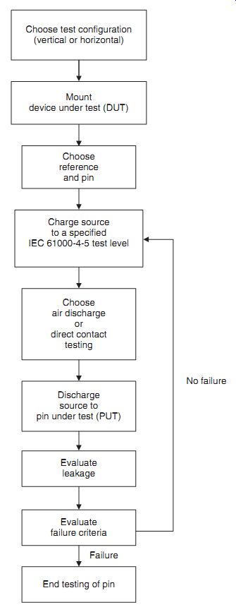
FIG. 6 IEC 61000-4-5 test procedure
Failure mechanisms on a system level can be destructive and nondestructive events. The following responses of the IEC 61000-4-2 test can be defined as failure mechanisms [1]:
• Loss of operation, loss of function, or temporary degradation that is recoverable by system self-recovery or "self-healing" function
• Loss of operation, loss of function, or temporary degradation that is nonrecoverable by sys tem self-recovery or "self-healing" function requiring operator intervention (e.g., power down, power up, or system reset)
• Loss of operation, loss of function, or nonrecoverable degradation that is nonrecoverable and damage to the system, components, software, or data
• Permanent damage to the components and system.
9. IEC 61000-4-5 ESD Current Paths
Current paths from the IEC 61000-4-5 involve both signal pins and power rails. In this test, a significant focus exists on interaction of the circuitry and the ground connections. The ground connection can be a source of the transient phenomena. In the following section, solutions used for protection in the ground connections are discussed.
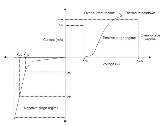
FIG. 7 IEC 61000-4-5 ESD protection circuit I-V characteristics
10. ESD Protection Circuit Solutions
ESD protection circuit solutions include solutions between pins and ground connections.
Diodes are used to provide protection for positive and negative transient surges [28-40].
FIG. 7 shows an example of a diode protection element. The circuit element must survive the peak pulse current (IPP). In addition, the protection device is to limit the surge voltage (VCL). FIG. 7 shows the positive region and the negative region with the defined electrical parameters of the diode protection element.
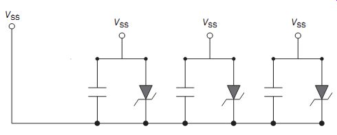
FIG. 8 IEC 61000-4-5 ESD protection circuit for ground connections The
peak pulse current, IPP, should be above the current in the IEC 61000-4-5
standard that requires an 8 µs/20 µs response.
FIG. 8 is an example of a protection strategy between the ground connections using a capacitor and a breakdown diode. The ground connections are all connected to a common ground point.
11. Alternate Test Methods
For telecommunication lines, the test equipment is modified to address the distinction com pared to other events. Telecommunication lines are vulnerable to lightning through both direct and indirect. Telecommunication lines can also be disturbed by power induction, or power transfer with the main AC lines.
An example of a telecom compliant test system that is compliant with the IEC 61000-4-5 specification can generate a voltage waveform of 10 µs rise time and a 700 µs duration. The peak voltage can achieve 250V to 6.6 kV. The peak current of 6.25-165A can be sourced in a 40-Ohm mode. The repetition rate of these test systems can provide multiple pulses in a minute (e.g., maximum of four pulses in 1min). For an open-circuit voltage, a voltage waveform of 7-11.7 µs rise time and a 576-840 µs duration, and a 30% undershoot. For a short circuit volt age, a voltage waveform of 3.5-6.5 µs rise time and a 256-384 µs duration. External couplers are also used for telecommunication lines. For a Telcordia GR-1089 core, specific surges are defined as 2 µs rise time and a 10 µs duration, and a second 10 µs rise time and a 1000 µs duration. Alternate standards exist for the rise time and pulse duration for telecommunication systems.
12. Summary and Closing Comments
This section addressed system level transient surge concerns in semiconductor development, known as IEC 61000-4-5. This test introduces a transient oscillation. With the growing interest in system level EOS, the interest in this test has emerged recently in semiconductor chip suppliers, to test equipment. The section addresses the purpose, the scope, and the pulse waveform. ESD protection concepts for the IEC 61000-4-5 were also discussed.
Section 10 addresses a new semiconductor chip level test to addresses a cable discharge event (CDE). This test, the CDE, introduces a fast transient followed by a slower square pulse waveform. With the growing interest of ports and smaller systems, cable discharge events are of increase for both chip developers and system designers.
Problems
1. The IEC 61000-4-5 is a direct contact transient test. How does the IEC 61000-4-5 test compare to the human metal model (HMM) test? What are the differences?
2. What are the differences of the IEC 61000-4-2 test and the IEC 61000-4-5 test? Are the purpose and scope of the tests different?
3. The IEC 61000-4-5 test is an oscillatory waveform. What is the difference between the IEC 61000-4-5 test and the machine model (MM) test?
4. The IEC 61000-4-5 test was developed for transient surge phenomena. How does it differ from a transient latchup (TLU) waveform?
5. Can the IEC 61000-4-5 test cause system level latchup? Why or why not?
6. The human metal model (HMM) was a direct contact version of the IEC 61000-4-2 standard. Is there an equivalent for the IEC 61000-4-5 test?
7. The IEC 61000-4-5 was defined to be used on a system. What are the potential failure mechanisms when injected into a printed circuit board (PCB)?
8. The IEC 61000-4-5 was defined to be used on a system. What are the potential failure mechanisms when injected into a semiconductor chip?
9. Can the IEC 61000-4-5 test induce CMOS latchup inside a chip mounted on a PCB? What are the potential issues of board-chip capacitance coupling and how will that influence the response?
References
[not listed]