AMAZON multi-meters discounts AMAZON oscilloscope discounts
1. Measurement: The Basics
1.1 Uniformity, Reliability, and Accuracy
We do not measure things. Rather, we measure properties of things. For example, we cannot measure a box, but we can measure its properties such as its mass, length, and temperature.
To properly compare and analyze the things in our universe, we need to com pare and analyze their properties. Because people all around the world are making measurements, we must ensure there is agreement on all the various types of measurements used. Difficulties arise because measurements have both quantitative and qualitative aspects. The fact that the two lines on the international prototype platinum-iridium bar in France are one meter apart is quantitative; how you mea sure other objects with that bar is qualitative. The ability to match up two lines may seem simple, but, depending the desired accuracy, such simple operations are in fact difficult. This difficulty is why using measuring equipment is a qualitative art.
No one uses the prototype meter as an actual measuring tool; rather, copies are made from the original prototype, and these copies are used as masters to make further copies. By the time you purchase a meter stick, it is a far distant cousin from the original meter prototype. However, despite the length of the progeny line, you hope that the copy you have is as good as the original. Depending on the expertise of the engineers and machinists involved, it should be very close. To obtain that quality, the engineers and machinists were guided by three factors;
uniformity, reliability, and accuracy. Without these basic tenets, the quality of the meter stick you use would be in doubt. Likewise, the quality of the use of the meter stick is also dependent on the same three factors, without which all readings made would be in doubt.
Uniformity requires that all people use the same measurement system (i.e., metric vs. English) and that all users intend that a given unit of measurement rep resents the same amount and is based on the same measurement standard used everywhere else. It is the user's responsibility to select equipment that provides measurements that agree with everyone else.
Reliability requires the ability to consistently read a given measurement device and also requires a given measurement device to perform equally well, test after test. It is the user's responsibility to know how to achieve repeatable data from the equipment being used.
Accuracy refers to how well a measurement device is calibrated and how many significant figures one can reliably expect. It is the user's responsibility to know how to read his equipment and not interpolate data to be any more accurate (i.e., significant figures) than they really are.
Laboratory research is dependent on reliable quality measurements and the use of uniformity, reliability, and accuracy to achieve this goal and this cannot be emphasized enough. Poor or inaccurate measurements can only lead to poor or inaccurate conclusions. A good theory can be lost if the experimental data are misread.
Commerce is equally dependent on uniformity, reliability, and accuracy of measurement systems. The potential economic liabilities of mis-measurements and misunderstanding are easy to understand. In fact, it was the economic advantages of uniformity that led to the metric system's expansion after the Napoleonic wars.
What can upset and/or confuse consumers and businesses is when the same word (which may have varying meanings) is applied to different weights. We still con fuse the weight value of a ton and the volume of a gallon: In the United States, the ton is equal to 2000 lb; however, in Great Britain it is equal to 2240 lb. Similarly, in the United States, the gallon is established as 231 cubic inches; however, in Great Britain it is 277.42 cubic inches. If you are aware of these differences, you can make the appropriate mathematical corrections. But realistically, it should not be a problem to be dealt with. Rather, the problem of different measurement systems should be avoided in the first place. That is specifically was what the metric system was designed to do.
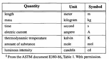
Table 1 Base SI Units
1.2 History of the Metric System
Overcoming the incongruities of inconsistent measurement systems on an international basis was considered for centuries. The basics of the metric system were first proposed by Gabriel Mouton of Lyon, France, in 1670. This vicar (of St. Paul's Church) proposed three major criteria for a universal measurement system: decimalization, rational prefixes, and using parts of the earth as a basis of measurement (length was to be based on the arc of one minute of the earth's longitude). There was also a desire to find a relationship between the foot and gallon (i.e., a cubic foot would equal one gallon). Unfortunately, these measurement units were already in use, and because there was no basis for these measurements to have any easy mathematical agreement, they did not. No simple whole number could be used to correct the discrepancy.
Gabriel Mouton's ideas were discussed, amended, changed, and altered for over 120 years. Eventually, a member of the French assembly, Charles Maurice Talley rand-Perigord, requested the French Academy of Sciences to formalize a report.
The French Academy of Sciences decided to start from scratch and develop all new units. They defined the meter as one ten-millionth of the distance from the North Pole to the equator. They also decided that the unit for weight would be based on the weight of a cubic meter of water in its most dense state (at 4°C). This plan allowed the interlinking of mass and length measurement units for the first time. In addition, they proposed prefixes for multiples and submultiples of length and mass measurements, eliminating the use of different names for smaller and larger units (i.e., inch/foot or pint/quart units).
On the eve of the French Revolution, June 19, 1791, King Louis XVI of France gave his approval of the system. The next day, Louis tried to escape France but was arrested and jailed. A year later from his jail cell, Louis directed two engineers to make the measurements necessary to implement the metric system.
Because of the French Revolution, it took six years to complete the required measurements. Finally, in June 1799 the "Commission sur l'unite de poids du Systeme Metrique decimal" met and adopted the metric system. It was based on the gram as the unit of weight and the meter as the unit of length. All other measurements were to be derived from these units. The metric system was adopted "For all people, for all time."
The metric system sought to establish simple numerical relationships between the various units of measurement. To accomplish this goal, the Commission took a cubic decimeter* of water at its most dense state (4°C), designated this volume as one "liter," and designated its mass (weight) as one "kilogram." In so doing, the commission successfully unified mass, length, and volume into a correlated measurement system for the first time. Official prototypes of the meter and kilogram were made and stored in Paris.
Because of Napoleon's conquests, the metric system spread rapidly throughout Europe. However, it was not in common usage in many areas (even in France) until international commerce took advantage of its simplicity and practicality. By the mid-1800s, it was the primary measurement system in most of Europe. In 1875 the International Bureau of Weights and Measures was established near Paris, France. It formed a new international committee, called the General Conference on Weights and Measures (CGPM), whose goal was to handle international matters concerning the metric system. The CGPM meets every six years to com pare data and establish new standards. Every member country of this committee* receives a copy of the meter and kilogram prototype with which to standardize their own country's measurement system.
Over the years there has been ongoing fine-tuning of the measurement system because the greater the precision with which our measurement units can be ascertained, the better we can define our universe. A new era in the measurement sys tem came in 1960, at the 11th meeting of the CGPM, when the International System of Units (SI) was established. This system established four base units: the meter, kilogram, second, and ampere. They are collectively known as the MKSA system. Later, three more base units were added: kelvin (for temperature), candela (for luminous intensity), and mole (for the amount of substance) (see Table 1).
In addition, two supplementary base units (which are dimensionless) were added: radian (plane angles) and steradian (solid angles) (see Table 2).
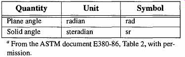
Table 2 Supplementary SI Units
[The National Institute of Standards and Technology (formally the National Bureau of Standards) represents the United States at the CGPM. They store the United States' copies of the original measurement prototypes.]

Table 3 Derived SI Units with Special Names

Table 4 Some Common Derived Units of SI
From the nine base units, over 58 further units have been derived and are known as derived units. There are two types of derived units: those that have special names (see Table 3) and those that have no special names (see Table 4). An example of a derived unit with a special name is force, which has the unit newton (the symbol N) and is calculated by the formula "N = kg-^s 2." An example of a derived unit that does not have a special name is volume, which has the unit of cubic meter (no special symbol) and is calculated by the formula "volume = m^3."
Among the advantages of the International System of Units system is that there is one, and only one, unit for any given physical quantity. Power, for instance, will always have the same unit, whether it has electrical or mechanical origins.
In the United States, measurements made with metric units were not legally accepted in commerce until 1866. In 1875 the United States became a signatory to the Metric Convention, and by 1890 it received copies of the International Proto type meter and kilogram. However, rather than converting our measurement sys tem to metric, in 1893 Congress decided that the International Prototype units were acceptable as fundamental standards on which to base our English units.
Thus, the metric system was not implemented by the government and was not adopted by the nation at large.
By 1968 the United States was the only major country that had not adopted the SI system. Congress ordered an investigation to determine whether the United States should follow the International Standard. In its 1971 report, Congress recommended that we have a coordinated program of metric conversion such that within 10 years we would be a "metric country." With this hope in mind, President Ford signed the Metric Conversion Act of 1975. Unfortunately, as of the writing of this guide, in 1997, we see little evidence of "metrification." In the near future there may be difficulties for U.S. manufacturers because the European Common Market has decided that by 1992, it will no longer accept items not made to metric standards. Added to this is ISO 9000, a program to formalize procedures and methodology. Although not specifically required, it indirectly provides an advantage to those using metric systems.
If you look at the history of measurement, it shows constant attempts to better define and refine our measurement units. Early measurement standards were arbitrary such as the Egyptian cubit (the tip of the finger to the elbow). Since then we have tried to base measurement standards on non-changing, consistent, and repeatable standards, some of which turned out to be inconsistent and/or impractical. The work of the metrologist will never be complete. The more accurately we can define our measurement standards, the better we can measure the properties of our universe.
1.3 The Base Units
This guide focuses in on the original base units (length, mass, and temperature), plus one of the derived units (volume), because these measurements are the most commonly used measurements in the lab. Time is included in this section only because it provides an interesting commentary on the metrologists' desire to split hairs in their endeavor to achieve accuracy.
Length. The original metric standard for the length of a meter was " one ten millionth part of a quadrant of the earth's meridian." Astronomical measurements (at that time) indicated that one-tenth of a quadrant of the earth's meridian was measured between Dunkirk, in France, and a point near Barcelona, Spain. This distance was dutifully measured and divided by one million to obtain the meter. It is fortunate that the meter was later redefined, because if you take what we now call a meter and measure the distance between the Dunkirk and Barcelona points used, you get the length space of 1,075,039 meters. This space is an accuracy of only 7.5 in 100 meters.
Reproducible accuracy was increased substantially by the development and use of the International Prototype Metre, the platinum-iridium bar. By physically comparing the lines on this bar with a secondary prototype, an accuracy was achieved to within two parts in 10 million.
In 1960 (at the same meeting during which the International System of Units was accepted) the meter was redefined as being 1,650,763.73 wavelengths (in vacuum) of the orange-red spectral line of krypton-86. This system had several problems, chief of which was that this figure could only be reached by extrapolation because it was not possible to extend an accurate quantity of waves beyond some 20 centimeters. To obtain the required number of wavelengths for a meter, several individual measurements were taken in succession and added together. This measurement procedure, because of its nature, increased the likelihood for error.
Despite the limitations of the krypton-86 based meter, it brought the accuracy to within two parts in 100 million.
In 1983 yet another definition of the meter was adopted: It was the distance that light would travel (in a vacuum) during 1/299,792,458 of a second. This attempt provided a measurement ten times more accurate than that obtained through krypton-86 techniques. This meter, accurate to within four parts in one billion, is still in use today.
Mass. The kilogram is unique in several aspects within the metric system. For one, it is the only base unit that includes a prefix in its name (the gram is not a base unit of the International System of Units). Also, it is the only base unit defined by a physical object as opposed to a reproducible physical phenomenon.
The kilogram was based on the weight of one cubic decimeter of water at its most dense state (4°C). The original "standard mass kilogram" was made by constructing a brass weight, making careful weighings (using Archimedes' Principle), and then making an equivalent platinum weight. The platinum weight is called the Kilogramme des Archives and is kept at the International Bureau of Weights and Measures near Paris, France.
About a hundred years later during studies verifying previous data, it was discovered that a small error in the determination of the kilogram had been made.
The problem was caused by the consequences of very small variations of temperature causing very small variations in density, which in turn caused inaccurate weighings. The CGPM decided against changing the mass of the kilogram to a corrected amount; rather, it accepted the mass of the kilogram as being that obtained from the original Kilogramme des Archives.
[Simply stated, a submerged body is buoyed up by a force equal to the weight of the water that the submerged body displaces. In other words, if an object weighs 1.5 kilograms in air, and the weight of the water it displaces is equal to 1.0 kilogram, the object will weigh 0.5 kilograms in water.
A copy of the prototype is held by the National Institute of Standards and Technology (formally the National Bureau of Standards) and by all other countries who have signed agreements following the International System of Units.]
It has been hoped that there will be some naturally occurring phenomenon in nature to which we can ascribe the value of the kilogram, thus allowing the kilo gram to be based on a reproducible phenomenon rather than relying on a physical artifact. Although there have been several efforts toward this goal, such as counting molecules, our current technological level cannot achieve any greater accuracy than that obtained by simply comparing weights of unknowns against our current prototypes.
Volume. As previously mentioned, the unit for volume (the liter) was to be one cubic decimeter of pure water at its most dense state (4°C). Later analysis deter mined that errors were made in the determination of the kilogram and that the mass of one decimeter of water was slightly less than the prototype kilogram.
However, the use of the kilogram as it had already been defined was so well established that change became impossible. Thus, in 1872, the "Commission Internationale du Metre" met to redefine the kilogram as the mass of a particular standard weight (the Prototype Kilogram) instead of the weight of a liter of water.
The concept of the liter was cast into doubt. Was it to be based on the weight of a standard volume of dense water as before, or was it to be an alternate name of the cubic decimeter? The first attempt to resolve the conflict was in 1901 when the "Comite International des Poinds et Mesures" resolved that "The unit of volume for determinations of high precision is the volume occupied by a mass of 1 kilograms of pure water at its maximum density and under normal atmospheric pressure." This volume, so defined, was identified as a "liter."
However, this designation still left the discrepancy that this definition actually redefined the liter to be equivalent to 1.000027 dm^3. There was once again a discrepancy as to what a liter was. So, at the 12th conference of the "Comite International des Poinds et Mesures," the unit of volume was redefined for the last time as the cubic decimeter. The liter, no longer the official unit of volume, was nevertheless so close to the cubic decimeter in size that unofficially it was deemed acceptable to continue its use; however, for situations that required extremely high-quality measurements, only the cubic decimeter was acceptable. The cubic decimeter remains the standard of volume today.
Temperature. Temperature was not one of the original properties that the French academy deemed necessary to include in the metric system. In fact, as late as 1921, members of the 6th General Conference of the International System of Weights and Measures were still objecting to the inclusion of measurements (other than length and mass) seemingly for no other reason other than to keep the base units "pure." The measurement of temperature is a measurement of energy and therefore has different measurement characteristics than other properties. The primary difference in temperature measurement is that it is not cumulative. You can take two different meter sticks and place them end to end to measure something longer than one meter. The comparable action can be made for the measurement of mass.
However, you cannot take two thermometers and add the temperature of the two if a material's temperature is greater than the scale of either thermometer.
The first thermometer is believed to have been created by Galileo sometime between 1592 and 1598. It was a glass sphere attached to one end of a long, thin glass tube. The other end of the glass tube was lowered vertically into a bowl of colored water (or perhaps wine). Using the warmth of his hands, Galileo heated the glass sphere, causing bubbles to come out of the glass tube. Then, by letting the sphere cool to room temperature, Galileo caused the liquid to be drawn up into the tube. By heating and/or cooling the glass sphere, the liquid would ride up and down the tube.
Although there is no record that he ever calibrated the tube, he used it in temperature study. Galileo's thermometer was impossible to calibrate even if he had decided on fixed points with which to establish specific temperatures because it was exposed to the atmosphere and subject to variations in atmospheric pressure.
By 1640, it was realized that the "air thermometer" was subject to variations of barometric pressure and the sealed thermometer was created. However, the need to establish fixed points of reference had still not been addressed.
The need to establish fixed points to provide uniformity between thermometers is no different than the need for uniformity with any measurement system. Many thermometers were built in the following years, but either there was no calibration, or the calibration was not based on any repeatable fixed point. One of the first attempts of establishing calibration points was made in 1693 by Carlo Renaldini of Padua, who set the low temperature point with ice. For the next point, he took 11 ounces of boiling water and mixed it with one ounce of cold water. Next he mixed 10 ounces of boiling water with two ounces of ice water. The process continued until 12 divisions were established on the thermometer. Although Renaldini had an interesting approach to establishing fixed points on the thermometer, it was neither practical nor accurate.
The first commonly used temperature measurement scale was devised in 1724 by the Dutch scientist D. Gabriel Fahrenheit. It took 16 years for Fahrenheit to devise a process for calibrating his scales. Fahrenheit used three points for calibration. The lowest, 0°, was the lowest temperature he could create by mixing ice, water, and ammonium chloride (a slush bath of sorts). The second temperature was ice, at 32°, and the high temperature point was the human body temperature, 96°. The choice of identifying the low temperature was logical, but the choice of the high temperature seems illogical. Lindsay assumed that 96 was chosen because it was an even multiple of 12. However, I haven't seen any evidence that the Fahrenheit scale was ever divided into multiples of 12. Also, the human body is closer to 98°. If the scale was originally based on a duodecimal system and changed to a decimal system, the human body would be 100° Fahrenheit. Regard less, if the human body were fixed at 96°, that fixed point would not change as thermometers were made more accurate. Regardless of the logic Fahrenheit used for his scale, his quality was excellent and his thermometers became very popular.
In 1742 Anders Celsius, a Swedish astronomer, developed the mercury centigrade thermometer. He chose the boiling and freezing points of water as calibration points. Curiously, he chose 0° for the high temperature and 100° for the low temperature. His choices were reversed in 1850 by Marten Stromer, also a Swedish astronomer. In 1948 the centigrade scale was officially renamed the Celsius scale.
During the early 19th century, Lord Kelvin theorized that as temperature drops, so does thermal motion. Thus, 0° should be the point at which there is zero motion. This new 0° temperature would be equal to -273.15 degrees Celsius. Fortunately, Kelvin had the foresight to keep things simple, and made a 1-degree increment Kelvin exactly equal to a 1-degree increment Celsius. Originally, the temperature Kelvin was capitalized. Now, it is not capitalized, and should be writ ten as kelvin. The abbreviation of kelvin is capitalized and written as K.
There are two other temperature scales that still may be seen in old texts or journals, but are not acceptable for any current scientific work. Perhaps the rarer is the Reaumur scale (°Re). It separated the range between freezing and boiling of water into 80 units and was used in parts of Europe. The other temperature scale, the Rankine, may be referred to in old books on thermodynamics. It was named after W. J. M. Rankine, who did early research in that field. The Rankine is to Fahrenheit what Kelvin is to Celsius. In other words, just as one degree K = one degree C, one degree F = one degree R. Thus, 0 K = 0°
R = -273.15°C = -459.67°F.
In 1954 the General Conference wanted to redefine the temperature scale using various primary points in addition to the two points of freezing and boiling water.
The triple point of water (at 273.16 K) proved easy to obtain and very accurate (one part in a million). In 1960 the triple point of water and five other fixed points were accepted for an International Practical Temperature Scale. This scale was superseded in 1968 by the International Practical Temperature Scale (IPTS 1968), which added eight more fixed points. The current scale is shown in Table 29.
[The Royal Society of London in the early 1700s used a reversed scale that describes 0° as "extreme hot" and 90° as "extreme cold." Measurements in kelvin are not preceded by the "°" symbol.
Six different points were adopted because no one thermometer can read a full range of temperatures, and no one thermometer can read a wide range of temperatures accurately. Thus, different fixed points allowed for thermometers measuring different ranges to be accurately calibrated.]
Time. How long is a second, and how do you store that measurement? Various attempts at measuring the length of a pendulum swing proved inadequate for the task of accurately measuring the points of a given swing. The people who devised very complex and systematic methods for defining the metric system did nothing for time. During that period of time, 1/86,400 of a mean solar day was considered to be an adequate definition of one second. However, by the mid-1900s the mean solar day was found to vary by as much as three seconds per year. In 1956 the International System of Weights and Measures denned the second to be "1 / 31,556,925.9747 for the tropical year 1900 January 0 at 12 hours ephemeris time."
In 1960 this standard was accepted by the General Conference with the caveat that work continue toward development of an atomic clock for the accurate measurement of time.
The atom exhibits very regular, hyperfine energy-level transitions and it is possible to count these "cycles" of energy. In 1967 the General Conference accepted 9,192,631,770 cycles of cesium-133 as the measurement of one second, making the atomic clock the true international timekeeper. The cesium clock is maintained in Boulder, Colorado, in the offices of the National Institute of Standards and Technology (formally the National Bureau of Standards). Its accuracy is one part in 1,000,000,000,000 (10^12 ). It will not gain or lose a second in 6000 years.
1.4 The Use of Prefixes in the Metric System
One of the strengths of the metric system is the consistency of its terms. In other measurement systems, the names for measures change as the size of the measurements change. For instance, consider the changes in the English measurement sys tem for length (inch-foot-yard), weight (ounce-pound-ton), and volume (ounce quart-gallon). In the metric system, all measurement names consist of a root term that, by use of prefixes, yields fractions and multiples of the base measurement unit.
The metric system is a decimal system, based on powers of 10. Table 5 is a list of the prefixes for the various powers of 10. Between scientific notation and the prefixes shown below, it is very simple to identify, name, read, and understand 36 decades of power of any given base or derived unit.
Ephemeris time is a uniform measure of time defined by the orbital motions of the planets.
1.5 Measurement Rules
There are several general rules about making measurements. These rules are standard regardless of the type of equipment being used, material being studied, or the measurement units being used.
1. The quality of the measurement is only as good as the last clearly read number. No matter how obvious an estimated number may seem, it is not as reliable as the one your equipment actually provides for you. For example, see FIG. 1 and FIG. 2. If you want greater accuracy in your readings, you need better equipment, which pro vides more precise measurements. One safe way to indicate greater accuracy is to qualify a number. In the case of FIG. 1, you could write 6.2 + 0.2. The selection of ±0.2 is somewhat arbitrary, as the length is obviously greater than 6.0, yet smaller than 6.5.
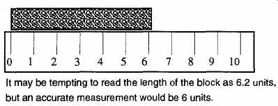
FIG. 1 The degree of accuracy obtainable for any given reading is limited
by the quality of your equipment.
2. Remember the limits of significant figures. The numbers 8.3 and 0.00083 both have two significant figures. The number 8.30 has three.
Any calculations made can only be as good as the minimum number of significant figures. Before the mid-1970s, three significant figures were often the standard, because most calculations were made on slide rules which had only three significant figures. With the advent of digital readouts and calculators, the use of more significant figures is common.
3. Be aware of equipment error. Measuring tools can be improperly calibrated or otherwise inaccurate. This problem can be the result of improper use or storage, or faulty manufacturing. To guard against inaccuracy of tools, maintain periodic records of calibration tests.
When the results are off the nominal values, your records will help pinpoint the time frame when the inaccuracies started. All data made prior to the last verification test should be discarded or held in question.
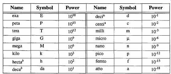
Table 5 Powers of the Metric System " From the ASTM document E380,
Table 5 , reprinted with permission.
To be avoided where practical. (Although the SI prefers avoidance of these "power" names, the centi s still commonly used.)
FIG. 2 It is important to read only to the limits of your equipment.
4. Be sure the equipment is used in the proper environment. Some equipment is designed to be used in limited environmental conditions. For example, a vacuum thermocouple gauge is calibrated for readings made in specific gaseous environments. If the vacuum sys tem contains gases other than those the gauge was designed to read, inaccurate pressure data will result. In addition, variables such as temperature, elevation, drafts, and whether the equipment is level can all affect accurate performance.
5. Be aware of user error. Many errors are caused by the operator, through sloppy readings or lack of experience with particular equipment. Be sure you know how to read your equipment and how to make any necessary conversions of your readings to the units that you are using (i.e., microns to torr).
6. Avoid parallax problems. A "parallax" problem occurs when the object being observed is not placed directly between the eye and measuring device, but rather at an angle (see FIG. 3) between the two. An incorrect sighting is easy to avoid, but requires conscious effort. Parallax problems show up with linear as well as liquid measurements.
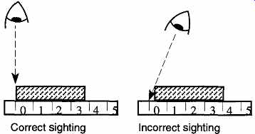
FIG. 3 Correct and incorrect sightings of an object.
7. Make many readings. This form of cross-checking proves that your work is reliable and reproducible. It is unscientific to make conclusions based on a limited amount of data. On the other hand, there has to be a limit on the number of data collected because too much data wastes time and money. Collect a statistically viable amount of data, but be guided by common sense.
8. Keep your instruments and equipment clean. Filth cannot only chemically affect the materials of your experiment, it can also affect the operation of your measuring equipment. Therefore, just as your experimental equipment must be kept clean, it is equally important that your analysis and recording equipment also be kept clean. For example, if the mercury in a McLeod gauge or manometer is dirty, the manometer or McLeod gauge will not provide accurate readings.
Similarly, if pH electrodes are not stored in a proper, standard solution, they will not provide accurate readings. Even fingerprints on objects used for weighing can affect the final weight. You are not likely to produce results worthy of note (let alone reproducible results) if your equipment is so filthy that the mess is obscuring or affecting your readings.
2. Length
2.1 The Ruler
It is appropriate that the object used to measure length is called a ruler. The dictionary's definition of a ruler is "a person who rules by authority."
It therefore makes sense that the final arbiter of an object's length should be known as a ruler.
In the laboratory, the ruler is the meter stick. The meter stick may have inch measurements on one side (1 meter = 39 3/g inches), but a yardstick, or any ruler of 6, 12, or 18 inches has limited value in the laboratory unless it also has metric measurements in addition to English measurements.
2.2 How to Measure Length
Because measurements using a meter stick are straightforward, no explanation is provided. There are, however, two possible complications when using a meter stick. One problem is reading beyond the limits of the measurement device, and the other is parallax (see FIG. 1, FIG. 2, and FIG. 3).
Meter sticks have major limitations in that they can only measure flat objects.
For example, it is impossible to accurately measure the outside diameter of a round-bottom flask, the inside diameter of an Erlenmeyer flask neck, or the depth of a test tube with a meter stick. Fortunately, there are various devices and techniques that can be used with the meter stick. The three limitations just mentioned can be resolved with the aid of other tools, as shown in FIG. 5 and FIG. 4.
Aside from meter sticks, there are other instruments used for linear measurement such as the caliper and micrometer. Their designs and mechanisms for use are very different, but both meet specific needs and have specific capabilities.
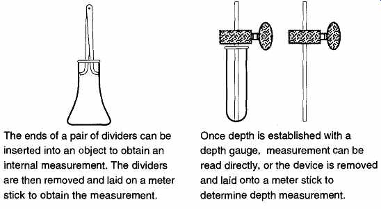
FIG. 4 How to measure the inside diameter and length of an object.
The ends of a pair of dividers can be inserted into an object to obtain an internal measurement. The dividers are then removed and laid on a meter stick to obtain the measurement.
Once depth is established with a depth gauge, measurement can be read directly, or the device is removed and laid onto a meter stick to determine depth measurement.
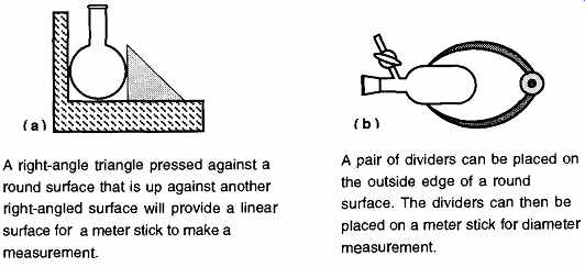
FIG. 5 How to measure the outside diameter of rounded objects.
A right-angle triangle pressed against a round surface that is up against another right-angled surface will provide a linear surface for a meter stick to make a measurement.
A pair of dividers can be placed on the outside edge of a round surface. The dividers can then be placed on a meter stick for diameter measurement.
2.3 The Caliper
Although the caliper is not the most commonly used measuring device used by the machining industry (the micrometer has that award), it has still tends to be limited by American industries resistance against metrics. Thus, finding a good-quality caliper with metric units may take some looking. Fortunately, the inexpensive metal calipers (with both English and metric measurements) found in a hardware store are fine for ±0.2-mm accuracy. The plastic calipers also found in hardware stores are not recommended for anything.
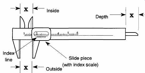
FIG. 6 The caliper and its three measurement capabilities
A good-quality caliper can provide an accurate measurement of up to ± 0.05 mm (+ 0.002 in.). For more accurate measurements [± 0.0003 mm (± 0.0001 in.)], a micrometer is used. The micrometer is discussed in Sec. 2.2.4.
The caliper has one moving part, called the slide piece, with three extensions.
The extensions of the slide piece are machined so that they can make an inside, outside, or depth measurement (see FIG. 6). To achieve greater precision, all calipers include vernier calibration markings on their slide piece. The vernier calibration markings allow measurements one decade greater than the markings on the caliper. The length of the vernier's 10 units on the side piece are only nine units of the ruler markings on the body of the caliper (see FIG. 7). Fortunately, you do not need to know the geometry or mathematics of how a vernier system works to use one.
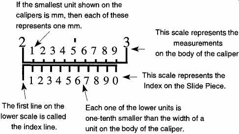
FIG. 7 This representation of the marks on a caliper body and slide piece
shows that 10 units on the slide piece are as long as 9 units on the caliper.
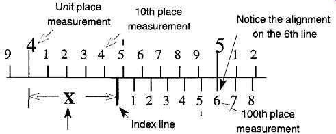
FIG. 8 How to read a vernier caliper.
The distance "X" is determined where the "index" line touches the upper scale (4.4) PLUS the number of the unit on the slide piece that best aligns with a line on the main scale (the 6th line) which provides the hundredth place measurement (0.06).
Therefore "X" is 4.46 caliper units.
This representation of the marks on a caliper body and slide piece shows that 10 units on the slide piece are as long as 9 units on the body of the caliper. A measurement reading on a caliper is made in two parts: the main unit and the tenth unit are made on the body of the caliper. The hundredth part is read on the slide piece. For example, to read the distance "X" in FIG. 8, first read the units to the left of the index line on the body's ruler. (The index line is after the 4.4 unit line.) Second, continue the reading to the 100th place by noting where the measurement lines of the slide piece best align with the measurement lines of the body. In this example, they align on the 6th unit of the slide piece. Therefore the 100th place is 0.06, and the total measurement of X is 4.46 units.
A dial caliper (see FIG. 9) is easier to read than a vernier caliper, but this ease comes at a price. An acceptable vernier caliper can be purchased for $30 - $50, and it can be found with metric and English measurements on the same tool. A good-quality dial caliper may cost between $75 and $150, and it shows only metric or English measurements. On the dial caliper, the 10th place is read on the numbers of the dial itself, and the 100th place is read on the lines between the numbers.
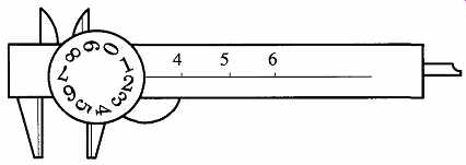
FIG. 9 The dial caliper.
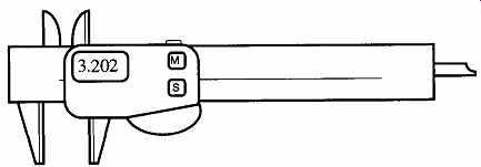
FIG. 10 The electronic caliper.
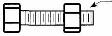
FIG. 11 The micrometer is a highly machined nut and bolt. If the threads
are cut at 50 revolutions per inch, 10 revolutions will move the nut one-fifth
of an inch, and one-half a revolution will move the nut one-hundredth of
an inch.
An electronic caliper (see FIG. 10) is more expensive ($100 - $200) than a dial caliper. However, electronic calipers can do a great deal more with greater precision [±0.013 mm (±0.0005 in)]. A measurement can be locked in by pressing a button; so, a measurement will not change even if the sliding part moves. Electronic calipers can alternate between metric and English measurements, can be zeroed anywhere so "difference" measurements can be read directly rather than subtracting or adding, and can be set to flash their numbers on and off when an object is out of maximum or minimum tolerance. A tape readout of measurements can be made with extra equipment.
2.4 The Micrometer
Another common tool for length measurement is the micrometer. Like the vernier caliper, in the United States, it is typically made with English measurements.
Whereas the caliper can provide precision measurement (to ±0.002 in.), you need a micrometer for greater precision (±0.0001 in.).
The micrometer is a very accurately machined machine bolt and nut. If you rotate a machine bolt into a nut a specific number of times, you'll notice that the bolt will have traveled a specific distance (see FIG. 11)
On the micrometer, the rotating handle is the nut, and the plunger is the machine bolt. FIG. 12 demonstrates how to read a micrometer.
A good-quality micrometer is not as expensive as a caliper of equal quality.
However, each design of a micrometer is capable of only one type of measurement and can measure only a limited range of that measurement (typically one inch). By comparison, the caliper can read inside, outside, and depth measurements. The caliper, as well, can read from zero to (typically) 6 inches. Therefore, to have an equivalent set of micrometers to do what one caliper can do would require up to 18 micrometers. Despite this shortcoming, a good machinist would not consider using a caliper for anything but a rough measurement and would insist upon using a micrometer for all final measurements.
To make a micrometer measurement, place the item to be measured against the anvil of the micrometer. Then, rotate the handle or ratchet until contact is made.
All final contact of the spindle against the measured item should be made with the ratchet. The ratchet provides limited control over the handle. Once it encounters resistance, it will spin with a clicking noise but will offer no more pressure against the handle. This feature guarantees consistent spindle pressure against the anvil for all readings.
A micrometer can also be used as a go/no-go gauge. The lock can be tightened, preventing the handle from rotating. Thus, by setting a measurement and by tightening the lock, the measurement is set. Then anything that fits (or does not fit) between the spindle and anvil is accepted or not accepted depending on your needs. For accuracy greater than 1/10,000 in., an air gauge is used. These gauges have accuracy to 1/1,000,000 in., and are used in the most demanding situations.
The air gauge is specialized beyond the scope of this guide, and no further explanation is included.
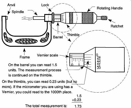
FIG. 12 How to read a micrometer.
3. Volume
3.1 The Concepts of Volume Measurement
It does not seem that it should be difficult to calculate the volume of any given container. First you establish a unit of volume, then you base everything on that unit. Despite the apparent simplicity of such a process, two widely divergent approaches to calculating a volume unit have developed.
One approach established that a liter was the volume of space occupied by the mass of one kilogram of distilled water (at 4°C and 30 inches of mercury). The other approach required a given length measurement to be defined (one decimeter), and then it defined the cube of that measurement as the volume measurement (one liter).
The original idea of the metric system was that either approach would provide the same unit of metric volume. Unfortunately, it did not work because of the subtle differences in density caused by subtle differences in temperature. Thus, the kilogram-based milliliter equaled 1.000,027 cubic centimeters. Because of the discrepancy, the International System for Weights and Measures had to make a choice between which approach would be accepted to obtain volume measurements, and the nod was eventually given to the cubic length technique. The use of liters and milliliters in volumetric ware is therefore misleading because the unit of volume measurement should be cubic meters (cubic centimeters are used as a convenience for smaller containers). The International System of Units (SI) and the ASTM accept the use of liters and milliliters in their reports, provided that the precision of the material does not warrant cubic centimeters. Because the actual difference in one cubic centimeter is less than 3 parts in 100,000, for most work it is safe to assume that 1 cm3 is equal to 1 mL.
3.2 Background of Volume Standards
Rigorous standards have been established for volumetric ware. These standards control not only specific standards of allowable error for volumetric ware, but the size of the containers, the materials of construction, their bases, shapes, and sizes, the length and width of index lines, and how those lines are placed on the glass or plastic. The painstaking work to establish these guidelines was done by agencies such as the NIST (National Institute of Standards and Technology), the ASTM (American Society for Testing and Materials), and the ISO (International Standards Organization)
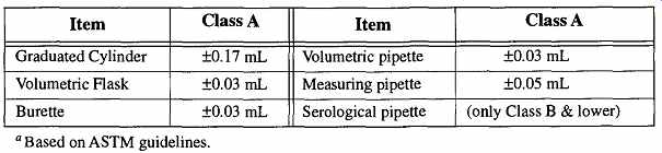
Table 6 Cross Comparison of Class A Volumetric Ware (25 mL)
Occasionally you may see references to Federal Specification numbers. For example, the Federal Specification number NNN - C 940-C is for graduated cylinders. All Federal Specification numbers are no longer being updated, and these specifications are being superseded by those established by the ASTM. The pre ceding number for graduated cylinders is now under the specifications of ASTM 1272-89. All ASTM documents are identified by a designation number. If there are updates to any document, the number will be followed by the acceptance year of the update. For example, the preceding example ASTM document cited shows that it was accepted by the ASTM for publication in 1989. If there is a conflict in ASTM guidelines, the document with the later publication date takes precedence.
All manufacturers abide by the standards set by these organizations. Therefore with the exception of quality and control, one manufacturer's volumetric ware (of comparable type) should not be more accurate than another manufacturer's. It is important to keep these guidelines in mind so that ASTM standards are not allowed to be used as marketing hype.
Manufacturers refer to these standards in their catalogs, both to let you know what you are buying and to enhance importance that may not otherwise be there.
For instance, only glassware made to specific established tolerances can have the symbol of "A" or "Class A" on their sides, signifying highest production quality.
For example, for a standard tolerance graduated cylinder, you may see statements in catalogs like "... conforms to ASTM Type I, Style 1 specs for volumetric ware." This description translates to mean "the graduated cylinder is made out of borosilicate glass (Type I) and has a beaded lip with a pour spout (Style 1)." In reality, this enhanced description is harmless and is much safer than statements saying "the most accurate graduated cylinder in town." Do not let the designation Class A mean more than it was meant to. Class A can only mean that it is the best tolerance readily available for that specific type of volumetric ware. Class A volumetric ware is not consistent across volumetric ware type. For example, a Class A volumetric pipette does not have the same degree of tolerance as a Class A measuring pipette. Equally, a Class A graduated cylinder does not have the same degree of tolerance as a Class A volumetric flask.
See Table 6 for a representative cross comparison of Class A tolerances.
In addition, do not be misled by ASTM designations. The words "Class," "Style," and "Type" are constantly used to describe different attributes to different types of variables in ASTM literature. They seldom refer to the same attribute.
Thus it is important to know what the identifying word is attributed to before assuming that you know what it is signifying. An example of these differences are shown in Table 7. The ASTM always refers to itself in its own specifications for equipment when describing one of its own procedures for a given test. That is, when they are performing a test, they must ensure that their guidelines are used when their equipment is selected. However, when you see manufacturer statements in catalogs describing (for example) a graduated cylinder that "... meets specifications of ASTM E133 for use in tests D86, D216, D285, D447, and D 850 ...," all the manufacturer is saying is that if you are performing any of these particular ASTM tests, this graduated cylinder satisfies ASTM requirements for use.
However, if the graduated cylinder meets ASTM El 33 requirements, by definition it can be used for tests D86, D216, etc. These descriptive entries not only are con fusing if you are unfamiliar with the numbers, but also provide blah-blah for marketing.
3.3 Categories, Markings, and Tolerances of Volumetric Ware
There are four categories of containers used to measure volume: volumetric flasks, graduated cylinders, burettes, and pipettes. Of the four, volumetric flasks are used exclusively to measure how much has been put into them. This use is known as "to contain." Graduated cylinders and a few pipettes are used to mea sure how much has been put into them as well as how much they can dispense.
The latter measurement is known as "to deliver." Burettes and most pipettes are used solely to deliver.
The term to deliver is based on the concept that when you pour a liquid out of a glass container, some of that liquid will remain on the walls of that container.
Because not all of the measured liquid is completely transferred, the material left behind should not be considered part of the delivered sample. Pipettes have two different types of to deliver. One which requires you to "blow out" the remaining liquid, and one that does not. Some volumetric containers are made out of plastic which does not "wet" like glass. Because these containers drain completely, the to contain is the same as the to deliver. Because some materials (i.e., mercury) do not "wet" the walls of any container, they should be used with only to contain measuring devices.
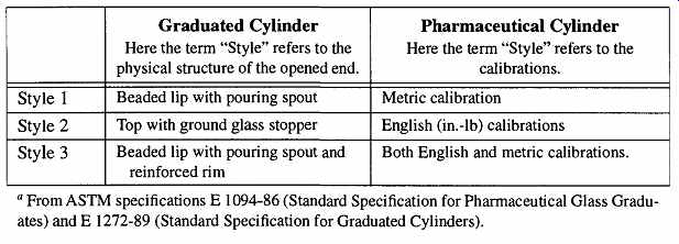
Table 7 "Style" Has Different Meanings'
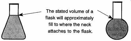
FIG. 13 The volume of flasks
The abbreviations TC and TD are commonly used to denote to contain and to deliver, respectively, in the United States. Old glassware might be labeled with a simple "C" or "D." The ISO (International Standards Organization) uses the abbreviations IN for to contain and EX for to deliver. These abbreviations come from the Latin root found in intra (within) and extra (out of). This classification has been accepted for use in the United States by the ASTM and is slowly being introduced by U.S. manufacturers. Because there have been no formal deadlines set, manufacturers are waiting for their current silkscreen printing setups to wear out by attrition and then replacing them using the new classification. Although some volumetric ware may be labeled with both English and metric calibrations, glassware is seldom labeled with both TD and TC calibrations. If you are ever using a volumetric container that is double-labeled, be careful that you are reading the scale relevant to what you are doing.
Other common laboratory containers such as beakers, round bottom flasks, and Erlenmeyer flasks often have a limited graduated volume designated on their sides. These markings provide an approximate volume and cannot be used for quantitative work. The required accuracy of these containers is only 5% of volume. When there are no calibration lines on a flask, it still is possible to obtain an approximate volume measurement based on the stated volume: In general, the stated volume will approximately fill any given non-volumetric container to the junction of the neck and container (see FIG. 13). Thus, if you need about 500 mL of water, it is safe to fill a 500-mL flask up to the neck and you will have approximately the needed volume.
The quality of any given volumetric ware is based on how accurate any given calibration line will deliver the amount it claims. For example, say that a one-liter flask is accurate to ±5%, meaning that the flask is likely to contain anywhere from 950 mL to 1050 mL of liquid. For comparison, a one-liter Class B volumetric flask is accurate to ±0.60 mL, or +0.06% accuracy, and a one-liter Class A is accurate to ±0.30 mL, or ±0.03% accuracy. Needless to say, it costs more for greater accuracy.
Precision volumetric glassware must be made following the standards set by ASTM Standards E542 and E694. These standards establish not only the degree of tolerance, but how the container is to be made, how the lines are engraved, the width and length of calibration lines, the type of glass used, the design and type of base (if any), the flow rate of liquids through tips, and many other limitations. In reality, if the manufacturers are properly following the ASTM guidelines, there is little room for any volumetric ware to be poorly made.
ASTM guidelines also establish that volumetric ware is to be calibrated at 20°C.
This (or any) constant is required because gases, liquids, and solids vary in size as temperature changes. Thus, any individual item is accurate only at one tempera ture. If manufacturers did not adhere to one temperature calibration, constant mathematical adjustments would have to be made as one switched from one brand of glassware to another.
There are four basic grades of volumetric ware:
1. Special Tolerance, also called Calibration Tolerance and Certified Ware. This glassware is calibrated not only to Class A tolerances, but to each mark on the glass. This calibration ensures high accuracy for every measurement. It needs to be specially ordered and calibrated.
2. Class A. This code is for the highest-class glassware that is production made. Some manufacturers refer to this grade as precision grade.
High-quality work can be performed using glassware that has this designation. The tolerance is the same as Special Tolerance, but in Class A it is based on a container's total capacity, not for each measurement division. Containers of Class A tolerance are always designated as such in writing on the side.
3. Class B. This classification is average grade glassware and can be used for general quality work. Some manufacturers refer to this quality as standard grade or standard purpose. By ASTM designation, Class B tolerances are twice those of Class A. The tolerance is based on a container's total capacity, not for each measurement division. Containers of Class B tolerance are seldom, if ever, designated as such in writing on their side.
4. General Purpose. This glassware is not accurate for any level of quality work. It is often referred to as student grade or economy grade.
Because the calibration is never verified, it is the most inexpensive volumetric glass available. The tolerance is limited to plus or minus the smallest subdivision of the container. Containers of general purpose tolerance are never specifically identified as such and therefore may be confused as Class B volumetric glassware. Such glassware made by Kimble is identified as "Tekk." Corning does not have a generic name for its student ware. General purpose glassware is often made out of soda-lime glass rather than borosilicate glass.
3.4 Materials of Volumetric Construction #1 Plastic
There are four types of plastic that are commonly used in volumetric ware:
polypropylene (PP), polymethylpentene (PMP or TPX), polycarbonate (PC), and polystyrene (PS). Plastic can be less expensive than glass, can be more difficult to break, and can be used equally well for to contain and to deliver measurements.
However, it cannot tolerate temperatures over 130° to 170°C (depending on the type of plastic), can be dissolved in some solvents, and the best quality available is Class B.
General Character of Each Type of Plastic.
Polypropylene is translucent and cannot be dissolved by most solvents at room temperature. It can crack or break if dropped from a desk.
Polymethylpentene is as transparent as glass and is almost as resistant to sol vents as polypropylene. It can withstand temperatures as high as 150°C on a temporary basis and 175°C on an intermittent basis. It can crack or break if dropped from a desk.
Polycarbonate is very strong and as transparent as glass. It is subject to reactions from bases and strong acids and can be dissolved in some solvents.
Polystyrene is as transparent as glass. It can be soluble to some solvents and because it is inexpensive, it is often used for disposable ware. It can crack or break if dropped from a desk.
Resistance to Chemicals. For a comprehensive list of plastic resistance to chemical attack.
Cleaning. Volumetric ware must be cleaned both to prevent contamination of other materials and to ensure accurate measurements. Because volumetric ware is often used as a temporary carrier for chemicals, it comes in contact with a variety of different materials which may be interreactive. Also, any particulate or greasy material left behind can alter a subsequent measurement.
Never use abrasive or scouring materials on plastic ware. Even though the bristles of a bottle brush are not likely to scratch plastic, the metal wire that they are wrapped on can! Scratches can alter volumetric quality, are more difficult to clean, increase the surface area open to attack by chemicals (that would otherwise be safe for short exposures), and can prevent complete draining from a to deliver container.
The following are some general cleaning guidelines for plastics:
1. Generally, mild detergents are safe with all plastic ware.
2. Do not use strong alkaline agents with polycarbonate.
3. Never leave plastic ware in oxidizing agents for an extended time because they will age the plasticizers and weaken the plastic. Chromic acid solutions are okay to use, but never soak longer than four hours.
4. Polystyrene should not go through laboratory dishwashers because of the high temperatures.
5. Polypropylene and polymethylpentene can be boiled in dilute sodium bicarbonate (NaHCO3), but not polycarbonate or polystyrene.
6. Sodium hypochlorite solutions can be used at room temperature.
7. Organic solvents can be used cautiously only with polypropylene. How ever, test each solvent before use for possible negative effects on the outside of the volumetric ware, away from a calibrated area.
Autoclaving. Polypropylene can be autoclaved, and polycarbonate can be auto claved for a limited time (<20 minutes) but can be weakened from repeated auto claving. The quality of volumetric measurements is likely to be eroded with repeated autoclaving. Polystyrene should never be autoclaved.
3.5 Materials of Volumetric Construction #2 Glass
Although glass is more likely to chip, crack, or break than plastic ware, it is safe to use with almost all chemicals. Type I glass can safely be put into a drying oven, and Type I and II glass can be autoclaved (glass types are explained below). No volumetric ware should ever be placed over a direct flame. Occasionally, tips and/ or ends of burettes or pipettes are tempered to provide additional strength. The tempering process typically used is heating followed by rapid cooling.
General Characteristics of Each Glass Type. Volumetric ware made of glass provides different properties depending on the type of glass used. The ASTM refers to the different glasses used in volumetric ware as Types. The use of the terms "Class A" and "Class B" in reference to types of glass have no relationship to volumetric quality.
1. Type I, Class A glass is usually Pyrex, Kimex, or Schott glass. It can be used for all classifications of volumetric ware. This glass is chemically inert, is repairable (in nonvolumetric regions away from calibration), can safely be placed in a drying oven, and can be fused onto other similar borosilicate laboratory glassware.
2. Type / , Class B glass is an aluminosilicate glass. It can be used for all classifications of volumetric ware. The trade names used are Corning's "Corex" glass or Kimble's "Kimex-51." They are more chemically resistant than standard borosilicate. However, they have larger coefficients of expansion and therefore cannot directly be fused onto other lab glass items made out of Pyrex or Kimex. An intermediary glass with a coefficient of expansion of about 40 x 10^-6 - 42 x 10^-6 is required for fusing Type I, Class B glass to Type I, Class A glass.
3. Type II glass is often identified as soda-lime, flint, or soft glass. Soda lime glass is not as chemically resistant as Type I glass, but short duration containment is acceptable (it is generally a good idea to not leave chemicals in soda-lime volumetric ware, particularly an alkaline chemical).
Type II volumetric ware cannot be repaired if cracked or chipped, nor can it be fused onto other laboratory ware. On the other hand, it is inexpensive and there fore commonly used for disposable ware and lower standard calibration ware.
Table 8 Effect of Heat Treatment on Volumetric Glassware
One type of Type II glass, Exax (from Kimble), has anti-static properties, which make it particularly suitable for powders.
Resistance to Chemicals. Exposure to all alkalines should be kept to a mini mum (minutes). Exposure to hydrofluoric and perchloric acid should be limited to seconds. Volumetric ware used once for these materials should be downgraded (glassware that was Class A should now be considered Class B) or not used at all.
If measurements of these acids or alkalines are required, use plastic ware because it is resistant to these chemicals.
Cleaning. All standard cleaning techniques used on glass are safe on volumetric ware. However, base baths and HF should never be used because they are glass stripping agents and because during the cleaning process they remove glass. This stripping would alter any calibrations, making the volumetric ware useless.
Contrary to common belief, it is safe to place borosilicate volumetric ware in a drying oven. While there has not been a study indicating the effects of heating on Type I, Class B or Type II glass, there was a study on Type I, Class A volumetric ware. The study was done by Burfield and Hefter, and the results (which are shown in Table 8) clearly indicate that any variations from the original volume are within tolerances even for Class A glassware.
The results of Table 8 notwithstanding, there still is the question of how to dry and/or store other types of volumetric glassware as well as plastic ware. First, plastic ware does not need oven drying because plastic does not absorb water.
Second, Type II glassware measurements will not be significantly affected by remaining distilled water (from the final rinse), so again there is no reason to dry this glassware. There is also no reason to dry to contain glassware between repeated measurements of the same solution. However, all other volumetric glass ware should be dried prior to use.
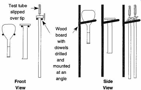
FIG. 14 Storage or drying of volumetric ware.
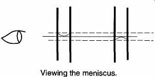
FIG. 15 Observe the center of the meniscus at eye level.
Because of contamination concerns, it is not recommended that you place volumetric ware on a standard drying rack because the pegs may introduce foreign materials into the container. It is also not safe to balance any volumetric ware on its end to drain or dry as it might be tipped over. Williams and Graves came up with an ingenious approach to drying and/or storage similar to how wine glasses are often stored. Although they limited their explanation to volumetric flasks, the idea can be expanded to any volumetric container with a bulge or protuberance at one end. Such volumetric ware items would include the base of a graduated cylinder or the stopcocks of a burette (see FIG. 14). This technique obviously will not work with pipettes.
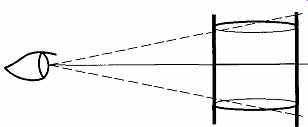
FIG. 16 By using the lines above and below the one you are sighting on,
you can avoid parallax.
FIG. 17 A piece of black flexible tube that facilitates seeing the meniscus.