AMAZON multi-meters discounts AMAZON oscilloscope discounts
<< cont. from part 1
3.6 Reading Volumetric Ware
The parallax problems of linear measurement are compounded with volumetric ware because there are two distinct lines to read. One line is where the liquid makes contact with the walls of the volumetric container, and the other is in the center of the volumetric tube (see FIG. 15).
The distortion of the liquid is caused by the surface tension of that liquid and the walls of the container. This distorted line is called the meniscus. When liquid wets the walls of a container, you read the bottom of the meniscus. When liquid does not wet a containers walls (such as mercury or any liquid in a plastic container), you read the top of the meniscus. Incidentally, if the glassware is dirty, a smooth meniscus cannot form and proper sighting is impossible; therefore, clean volumetric glassware is essential.
It may take a bit of practice to properly see the correct part of the meniscus line for accurate measurement. Fortunately, there are tricks and devices to facilitate the reading. For instance, if the graduation lines on the volumetric ware mostly encircle the tube, it is easy to line up your vision so that you can avoid parallax problems (see FIG. 16).
If the meniscus is difficult to see, you can make it stand out by placing a piece of black paper behind the glass tube, below the liquid line. The liquid picks up the dark color and, like a light pipe, the end of the liquid column will have a dark line.
Alternatively, the paper can be folded around the tube and can be held by a paper clip (like a French cuff). This "paper cuff' can be raised or lowered easily, and it frees both hands. Black paper is inexpensive and easy to use, but if the paper gets wet it will need to be replaced. This problem is not major, but if it occurs mid experiment, it can be an inconvenience.
Another technique that does not require paper uses a black ring cut from flexible tubing. These rings can be purchased to fit a variety of tube sizes, but if you have a hose of the right size available, they are easy to make by cutting out a disk from black tubing or by slicing a disk from a black rubber stopper (and a hole) and then cutting a wedge out of either disk (see FIG. 17). By sliding this ring up or down so that it is below the top of the liquid column, the meniscus can be easily seen.
3.7 General Practices of Volumetric Ware Use
After using volumetric ware, wash if necessary and always rinse thoroughly, first with water and then with distilled water. Although it is not necessary to dry to deliver volumetric ware between measurements (if the same chemical is being measured), it is necessary to dry the insides of to contain containers before use.
Reagent grade acetone or methyl alcohol may be used to facilitate drying.
If using volumetric ware for gravimetric calibration, unintended weight (i.e., dirt or fingerprint oils) may alter the results of any weighing. Therefore, be very careful where you place volumetric ware on a bench and how you hold it. You may choose to use cotton gloves to prevent fingerprint marks or handle all glass ware with tweezers or tongs.
Excess solution on the walls (inside or out) of volumetric ware adds weight to measurement, but are not considered part of the volume. Therefore, be careful not to splash your solution into the container. Such splashing can cause drops to settle on the side walls. To prevent splashing, place the tip of a burette or pipette against the walls of the receiving container so the liquid slides down the walls. This procedure should always be done above the calibration line. Wait a few minutes for any residual fluid along the walls to settle before making any final volume determination. Because fluids may cling to the walls of the container, it may take a few moments for everything to drain to its lowest level (for an exaggeration, think of honey). During the settling period, cap the container to limit the amount of fluid that would otherwise evaporate.
Do not leave alkaline materials in glass volumetric ware. Aside from the dam age they may do to the volumetric ware, dissolved glass can affect the pH of your solution. In addition, a glass plug or stopcock may freeze (stick) in place if left in contact with an alkaline solution. This freezing prevents the stopcock or plug from being turned or removed. A long-standing alkaline solution can roughen a surface of the glass barrel even in a Teflon stopcock. The rough surface can later scratch the surface of the Teflon plug when it is rotated.
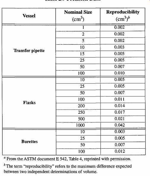
Table 9 Precision Data
3.8 Calibrations, Calibration, and Accuracy
The volumetric marks on volumetric ware are called calibrations. How they were located on the volumetric ware is called calibration. All volumetric ware is calibrated to provide its stated volume at 20°C. The International Standards Organization has recommended that the standard volumetric temperature should be changed to 27°C. However, so far there has not been any significant movement toward this goal. The ASTM recommends that those labs in temperate climates that are unable to maintain an environment at 20°C should maintain one at 27°C.
There are many labs that not only are unable to maintain a 20 °C temperature, but cannot maintain any temperature consistently. Temperature variations can create problems if you are attempting to do accurate work. The more accurate the work, the greater the need to maintain room temperature at 20°C. Alternatively, include the temperature of the liquid at the time of measurement in your experiment log. Then, at a later time, apply corrections to all measurements made to conform to ASTM 20°C measurements. However, do not waste your time doing unnecessary work. The correction for any given measurement may be irrelevant if either (1) its result is smaller than the tolerances of your equipment (2) it involves more significant figures than can be supported by other aspects of your work, or (3) you do not require that level of accuracy.
Another concern for accuracy is based on how accurately the user can read calibrations on the volumetric ware. The reproducibility of an individual user will be more consistent than the reading made by a variety of users. Therefore, if there will be a variety of users on any given apparatus, all who are likely to use it should make a series of measurements. This way, the individual errors can be calculated.
The ASTM has analyzed the range of errors made by trained personnel, and the reproducibility of these results are shown in Table 9.
For example, suppose you are calculating your car's "miles per gallon." It is a waste of time to mea sure the gas to hundredths of a gallon if your odometer can only read tenths of a mile.
3.9 Correcting Volumetric Readings

Table 10 Temperature Corrections for Water in Borosilicate Glass

Table 11 % Volume Corrections for Various Solutions"

Table 12 Corrections for Water Weight Determinations for Borosilicate
Glass Using a One Pan Balance (Nominal capacity 100 mL)
Volumetric readings can be made two ways. The easiest and most common is simply reading the volume directly from a piece of volumetric ware. Alternatively, you can weigh a sample and, if you know the molecular weight of the material, you can calculate the volume. Each approach can be affected by barometric pres sure, humidity, and temperature. The calculations and tables needed to obtain true volume from observed volume or calculated weight are not difficult to use but should only be used when necessary-that is, when accuracy or precision demand their use.
There are two different approaches for properly correcting volumetric readings caused by environmental variations because there are two approaches to making volumetric readings: those done by reading volume directly from volumetric ware, and those made indirectly by weight.
The simplest corrections are made when reading directly from volumetric ware.
As the volumetric container (and the liquid contained) expands and contracts by temperature variations from 20°C, volumetric corrections are required. These corrections can be found on Table 10.
For example, say you had a 100-mL borosilicate volumetric pipette whose liquid was measured at 24°C. Table 10 shows "-0.09" for these conditions, which means that you must subtract 0.09 mL from the stated volume to compensate for water and glass expansion. Thus you actually delivered only 99.91 mL of liquid.
You may occasionally see a soda-lime glass equivalent for Table 10, but I have not included it in this guide. Although soda-lime glass volumetric ware was common many years ago, it is not used for any accurate volumetric purposes today. It is unnecessary to provide highly accurate corrections for non-accurate glassware.
The corrections shown in Table 10 are only valid for distilled water. Different liquids will have different coefficients of expansions and therefore will require different corrections. Table 11 provides a few representative solutions at different normalities and a factor to correct Table 10 for volumetric discrepancies.
Corrections required when weighing volumetric flasks are somewhat different than straight volumetric readings. Both single- and double-pan balances have four common parameters which can affect the accurate weighing of liquids, but the single-pan balance has one separate parameter of its own. The common parameters are water density, glass expansion, and the buoyancy effect.
Water density varies because as materials get hot, they expand and take up more space. Despite their taking up more space, they still have the same mass and are thus less dense. One liter of hot water would therefore weigh less than one liter of cold water.
Glass expands as it gets hot. The effects of expansion of solid materials are well demonstrated with the ring-and-ball demonstration. In this demonstration, a ring is unable to get past a ball on the end of a rod. If the ring is heated just a small amount, it expands sufficiently to easily slide past the ball. In a similar fashion, a warm glass container holds more liquid than a cool glass container.
The differences in the buoyancy effect (based on Archimedes' principle) of materials in air at different barometric pressures is not as great as the buoyancy differences in water versus air, but it still exists and can affect accurate weighings.
The actual effect of these parameters on any measurement can be calculated by volumetric measurements. Then, their relative significance can be properly considered. The ASTM calculated the values shown in Table 13.
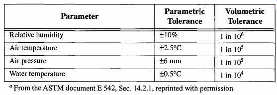
Table 13 Relative Significance of Environmental Parameters on Volume Measurements.
As Table 13 shows, for most laboratory work, the parameter that is likely to have the greatest effect on measurements when using a two-pan balance is water temperature. Any weight measurements made when the liquid temperature is not 20°C can be corrected by using Table 12. This table is used when the volumetric flask is Type I, Class A (borosilicate glass). It may also be used for Type I, Class B (aluminosilicate glass) by adding 0.0006 degree for every degree below 20°C.
Likewise, subtract 0.0006 degree for every degree above 20°C.
A sample calculation (using Table 12) for Type I, Class A glass is as follows:
Nominal capacity of vessel = 25.0 mL Temperature of weighing = 22.5°C Weight on pan before filling receiver = 24.964 g Weight on pan after filling receiver = 0.044 g Apparent weight of water at 22.5°C = 24.920 g Correction for 25 mL at 22.5°C (0.25 times* value in Table 2-13) = 0.083 Volume of vessel at 20°C = 25.003 mL As can be seen from this example, the correction is 10 times smaller than the tolerances capable from the flask itself (0.03 mL). Thus, to make the time spent on any such correction worthwhile, you need to see that any changes caused by temperature are at least equal to, or greater than, inaccuracies of the container. Other wise, do not bother with any correction.
It is interesting to note that for both Table 12 and Table 14, there are corrections for 20°C and 760 mm of atmospheric pressure. Because the glassware is calibrated for this temperature and pressure, one may wonder why a correction is necessary. The reason goes back to Archimedes' principle which cannot be accounted for when the glass is calibrated. The only way to avoid use of these tables at STP is to do all weighing in a vacuum to avoid the effects of air's weight.
Corrections for single-pan balances include the preceding parameters, plus a fourth one: the apparent mass of the built-in weights. The apparent mass of weights can vary somewhat from their true mass because the weights in a single pan balance were calibrated at a specific temperature and barometric pressure.
However, in a lab of different temperature and barometric pressure, you are weighing against their apparent mass.
Thus, when making accurate weighings with a single-pan balance, you must keep track of the temperature and barometric pressure of the room in which you are working.
[The figures in the tables are based on 100-mL sample sizes. The sample calculation is made with a 25-mL flask, therefore the calculations need to be multiplied by 0.25.
Old single-pan balances used brass weights with a specified density (at 20°C) of 8.3909 g/cm^3.
Now, stainless steel weights are used with a specified density of 8.0 g/cm^3. Fortunately, the differences of this change are too small for most purposes to be concerned about requiring any further calibration between the two.]

Table 14 Corrections for Water Weight Determinations for Borosilicate
Glass Using a One Pan Balance (Nominal capacity 100 mL)
Calibration correction tables for single-pan balances are provided in Table 14, which is used in the same manner as the previous example. Like Table 12, this table is used when a volumetric flask is Type I, Class A (borosilicate glass). It may also be used for Type I, Class B (aluminosilicate glass) by adding 0.0006 for every degree below 20°C. Likewise, subtract 0.0006 for every degree above 20°C.
[There are specialized volumetric flasks with calibration lines up the neck.]
3.10 Volumetric Flasks
Volumetric flasks are used to measure very precise volumes of liquids for making standard solutions or weighing for density calibrations. Each flask has one measurement line for the specific volume of the flask (see FIG. 18). Volumetric flasks are of either Class A or Class B quality; the tolerances for Class B are twice those for Class A. There are no general purpose volumetric flasks. The tolerances for the standard sizes of volumetric flasks are listed in Table 15. Volume calibrations were made at 20°C.
All volumetric flasks can be capped, thus preventing material in the flask from evaporating as well as maintaining the material's purity. There are three ways to close the top of a volumetric flask. Each type of cap can only be used with the proper corresponding volumetric flask. For example, a volumetric flask designed for a screw cap cannot use a snap-on cap or standard taper stopper. Each following type of cap is available for Class A and Class B flasks:
1. Plastic caps that snap on
2. Plastic caps that screw on
3. Standard taper stoppers made out of plastic or glass
The advantage of snap-on caps is that they are inexpensively replaced. They can also provide a small amount of protection against leakage if a flask is knocked over or is being agitated to mix the contents. The major disadvantage of a snap-on cap is that you need both hands to remove the cap. Screw-on plastic caps provide the best protection against spillage, but are more expensive. They also require both hands for removal.
Standard taper stoppers will prevent spillage only so long as the stopper is firmly in place, but they can be removed with only one hand. Plastic standard taper stoppers do not require grease, but may be chemically attacked by materials within the flask. Glass plugs placed over alkaline solutions without grease are likely to be frozen in place. On the other hand, the contents of the flask may dissolve any grease used.
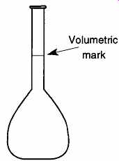
FIG. 18 The volumetric flask.

Table 15 Capacity Tolerances of Volumetric Flasks
From ASTM document E 288, Table 1. Omitted were columns entitled "Inside Diameter of Neck at Capacity Line (mm)," all information on the "Position of Capacity Line," and "Stopper Size," reprinted with permission
The proper procedure for filling a volumetric flask is as follows:
1. Carefully place the liquid to be measured into the flask using a pipette, burette, or any other device that can supply a steady stream against a wall, about a centimeter above the calibration line. Be careful not to splash. The tip may touch the wall.
2. When the level is just below the calibration line, cap the container and let it sit for a few minutes to let the liquid drain from the walls of the container.
3. Complete the filling process using Steps 1 and 2 again. If you overshoot the calibration line, a pasture pipette can be used to draw out excess fluid. The surface tension in the tip of the pipette should be sufficient to draw out the fluid. Once completed, cap the container.
The proper procedure for using a volumetric flask for gravimetric purposes is as follows:
1. Clean and dry (if necessary).
2. Weigh the flask, its cap, and any other materials that may be included in the final weighing.
3. If very accurate measurements are required, note the liquid's tempera ture and the room's barometric pressure and humidity.
4. Carefully place the liquid to be measured into the flask using a pipette, burette, or any other device that can supply a steady stream against a wall, about a centimeter above the calibration line. Be careful not to splash. The tip may touch the wall.
5. When the level is just below the calibration line, cap the container and let it sit for a few minutes to let the liquid drain from the walls of the container.
6. Complete the filling process using Steps 4 and 5 again. If you overshoot the calibration line, a pasture pipette can be used to draw out excess fluid. The surface tension in the tip of the pipette should be sufficient to draw out the fluid. Once completed, cap the container.
7. Weigh the filled flask.
8. If Step 3 was performed, repeat it to verify the readings.
9. Subtract the weighed flask by the empty flask weight.
10. If Steps 3 and 8 were performed, use the appropriate table and make any necessary corrections.
The procedure for using a volumetric flask for making a solution of a definite strength is:
1. Clean and dry (if necessary).
2. Carefully place the precalculated concentrated liquid into the flask using a pipette, burette, or any other device that can supply a steady stream against a wall about a centimeter above the calibration line. Be careful not to splash. The tip may touch the wall.
3. Follow this by adding to the flask distilled water up to the calibration line using a pipette, burette, or any other device that can supply a steady stream against a wall about a centimeter above the calibration line trying to rinse any of the concentrated liquid remaining on the flask's neck. Be careful not to splash. The tip may touch the wall.
When the level is just below the calibration line, cap the container and stop for a few minutes to let the liquid drain from the walls of the container.
4. Complete the filling process using Step 3 again. Try not to overshoot because any excess liquid will dilute the intended concentration.
For emptying a volumetric flask, the following procedure should be followed:
1. Slowly incline the flask to provide a steady stream of liquid from the spout. Be careful not to splash.
2. Continue inclining the flask until it is vertical and hold for about half a minute.
3. Touch the drop at the tip of the neck to the wall of the receiving container.
4. Remove the flask horizontally from the wall of the receiving container with no vertical motion.
3.11 Graduated Cylinders
Graduated cylinders are generally not used for high-quality volumetric work.
Although they are available in Class A, Class B, and Student Grade, the accept able tolerance of graduated cylinders is considerably greater than volumetric flasks (compare Table 15 to Table 0.1). Following standard practice, Class B tolerances are twice those of Class A. For specific capacities, graduations, and tolerances, see Table 0.1. Earlier federal specifications required more accurate tolerances on to contain than to deliver containers, but this case no longer applies and now both have the same tolerances.
There are three styles of graduated cylinders: Style 1 has a beaded lip and a pour spout, Style 2 has a ground standard taper joint on the top,* and Style 3 is just like Style 1 but has a heavy glass reinforcing bead just below the top for strength.
Graduated cylinders of Style 1 are manufactured in both to contain and to deliver designs. Graduated cylinders of Styles 2 and 3 are manufactured in to contain designs only. Often, graduated cylinders come with plastic or foam rubber cylinder guards to protect their tops if they are accidentally tipped. Use of these guards is highly encouraged.
Because liquids cannot wet plastic walls, plastic cylinders can provide constant volume for both to deliver and to contain. However, they are only accurate to Class B tolerances and susceptible to chemical attack from organic solvents.
Regardless of the quality, or construction design, graduated cylinders have no calibration lines at the section closest to the base because when the body is fused onto the base, the overall shape of the tube is distorted and accurate calibration on a production basis is not possible. This feature is equally applicable to graduated cylinders that use a plastic press-on foot.
[To receive standard taper stoppers.
Those smaller than 15 mL have vertical walls.]
Table 0.1 Dimensions and Tolerances of Graduated Cylinders
Pharmaceutical graduated cylinders, which can be identified by their non-vertical walls,* have poor accuracy. Their accuracy varies at any given inside wall diameter, even on the same flask. For instance, at regions where the inside diameter is between 21 and 25 mm, the accuracy is +0.4mL. However, at regions where the inside diameter is between 46 and 50 mm, the accuracy is ±1.8 mL.
To fill a to contain cylinder (Style 1, 2, or 3), the following procedure should be followed:
1. Clean and dry (if necessary).
2. Carefully place the liquid to be measured into the flask using a pipette, burette, or any other device that can supply a steady stream against a wall about a centimeter above the calibration line, being careful not to splash. The tip may touch the wall.
3. When the level is just below the calibration line, stop for a few minutes to let the liquid drain from the walls of the container.
4. Finish the fill using Steps 2 and 3 again. If you overshoot the calibration line, a pasture pipette can be used to draw out excess fluid. The surface tension in the tip of the pipette should be sufficient to draw out the fluid. If you are using a Style 2 cylinder, be sure not to get the ground joint wet with fluid. If the cylinder is a Style 2, cap the container to prevent evaporation or contamination.
For filling a to deliver cylinder (Style 1 only), the following procedure should be followed:
1. Clean (if necessary) for the first filling. If there is a water film, you may wish to rinse the cylinder with the liquid about to be measured to stabilize the molarity. Subsequent fillings do not require the rinse nor will they need a dry container.
2. Carefully place the liquid to be measured into the flask using a pipette, burette, or any other device that can supply a steady stream against a wall about a centimeter above the calibration line, being careful not to splash. The tip may touch the wall.
3. When the level is just below the calibration line, stop for a few minutes to let the liquid drain from the walls of the container.
4. Finish the fill using Steps 2 and 3 again. If you overshoot the calibration line, a pasture pipette can be used to draw out excess fluid. The surface tension in the tip of the pipette should be sufficient to draw out the fluid.
For emptying a to deliver cylinder (Style 1 only), the following procedure should be followed:
1. Slowly incline the cylinder to provide a steady stream of liquid from the spout. Be careful not to splash.
2. Continue inclining the cylinder until it is vertical and hold for about half a minute.
3. Touch the drop at the tip of the spout to the wall of the receiving container.
4. Remove the cylinder horizontally from the wall of the receiving container with no vertical motion.
3.12 Pipettes
There are three types of volumetric pipettes: volumetric transfer, measuring, and serological. The differences are based on whether the volume within the pipette is subdivided and if the volume in the tip is included in the calibration (see FIG. 19).
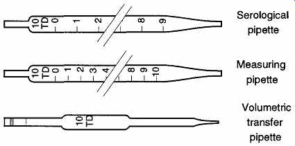
FIG. 19 The three types of pipettes.
The serological pipette is used to dispense varying volumes of liquid similar to the burette. Like a burette, the serological pipette is calibrated volume does not include the tip region. Volumetric pipettes are designed to dispense one volume of liquid, whereas the measuring pipette is calibrated to dispense varying volumes.
Both of these pipettes are designed to include the tip region in their entire dispensed volumes.
There are two different methods for completely draining a volumetric transfer or measuring pipette, and each method requires a different pipette design. One method is to leave the tip against the side of the receiving vessel and let the material drain into the vessel. This method leaves a small amount of solution remaining at the tip. The difference between this remaining portion and what has been transferred has been accounted for in the pipette's calibration. The other method of pipette draining requires the user to blow out the remaining liquid in the pipette; after all the liquid has drained out naturally, an extra burst of air is applied to the end of the pipette to expel any remaining fluid out of the tip. All blow-out pipettes are identified by either (a) an opaque band one-quarter of an inch wide or (b) two bands one-quarter inch apart at the end of the pipette.
There are pros and cons to both types of pipettes. The decision to use one or the other depends on the reliability, and repeatability, of your laboratory technique as well as the nature of the liquid you are pipetting. All non-blow-out pipettes are calibrated with water. Thus if your liquid has different surface tension or viscosity characteristics than water, your measurements will not be accurate. On the other hand, not everyone will exert an equal amount of blow-out force. Thus different people may deliver different volumes using the same equipment.
Pipettes often have color-coding bands on their ends to help identify them.
Although the colors are designated by the ASTM, they do not necessarily specify a specific volume. Their volumes do not necessarily correspond to any other pipette design. In fact, a given color may identify two volumes for any given type of pipette: however, pipettes with the same color band are always distinctively different in volume.
Traditionally, pipettes were filled by sucking fluid into the tube with the mouth.
This procedure, however, carries the risk of getting chemicals in the mouth. To protect the user, some pipette ends are designed to receive a cotton plug (see FIG. 20).
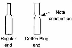
FIG. 20 Regular and cotton plug ends for pipettes.
The cotton plug allows gases past, but inhibits the flow of liquids. Thus, if a user sucked too hard, the liquid would clog the cotton plug and prevent the liquid from reaching the user's mouth. Although people still suck liquids into pipettes, the use of pipette fillers, or even rubber bulbs, are strongly recommended.
Volumetric Transfer. These pipettes are used to deliver a (single) specified volume. They are characterized by a bulb mid-span on the tube (see FIG. 19). The bulb is used to achieve greater capacity in the pipette and maintain the general length throughout the different volumes.
Volumetric pipettes are used solely to deliver in both drain and blow-out models. They are calibrated in both Class A and Class B tolerances based on guide lines established in the ASTM Designation E 969 - 83. Tolerances are provided in Table 16.

Table 16 Requirements for Volumetric Transfer Pipettes*

Table 17 Requirements for Measuring Pipettes"
The color-coding band(s) on the end of the volumetric pipette are used for quick identification purposes only. The repetition of the colors is sufficiently separated by the size of the pipette to not confuse (for instance) the 10-mL and 50-mL sizes.
To fill a volumetric measuring pipette, draw the solution to just above the volumetric level, then let the solution fall to the calibration mark. Remove the pipette from where you drew the fluid, and wipe the tip of the pipette with a laboratory tissue to remove any solution on the outside of the tip so it is not included with the dispensed liquid from the inside of the pipette. When draining a volumetric pipette, let the tip touch the side of the receiving container and let the fluid flow.
After emptying the pipette, count to two (to allow for any remaining fluid to flow to the bottom), and remove the tip sideways away from the receiving wall. Do not remove the tip with an upward or downward motion.
If the end of the pipette indicates the pipette is of blow-out design, gently (but firmly) provide (by lips or by the pipette filler) extra air pressure to "blow out" the last drop of liquid. Do not maintain a long continuous blow, especially if you are using the mouth to blow out the excess because you may contaminate your solution.
Measuring and Serological Pipettes. These pipettes have graduations along their sides. The difference is that the graduations on measuring pipettes stop before reaching the taper of the tip while the stated volumes of serological pipettes include the contents of the tip (see FIG. 19). Measuring pipettes should never be drained or blown out when delivering solution because the extra volume in the tip is not part of the pipette's calculated volume. Some serological pipettes are blow-outs, and others are not. You need to examine the end for the one-quarter-inch opaque mark Measuring pipettes come in both Class A and Class B and are available in two styles: Style 1 is a standard taper tip, and Style 2 is a long taper tip (Class B only).
Serological pipettes are only made to Class B tolerances and have no special styles. Volumes, tolerances, and other data of measuring pipettes are provided in Table 17. Information for serological pipettes is provided in Table 18. All calibrations were made at 20°C.

Table 18 Requirements for Serological Pipettes" Table 19 Tolerances
of Disposable (Serological) Pipettes
Class A pipettes have slower outflow times than Class B pipettes. This slowness provides the user with more reaction time to control liquid flow and thereby achieve better accuracy. It also allows the fluid draining from the walls to keep up with the fluid being dispensed from the tip. Otherwise you may dispense what you thought was 5 mL of liquid from a pipette, but after the liquid in the pipette settled, you discover only 4.9 mL of solution had been dispensed.
To fill a measuring or serological pipette, draw the solution to just above the volumetric level, then let the solution fall to the calibration mark. Remove the pipette from where you drew the fluid, and wipe the tip with a laboratory tissue to remove any excess solution from the outside of the pipette so that it is not included with the calibrated liquid.
When dispensing fluid from a measuring pipette, let the tip touch the side of the receiving container and let the fluid flow. If you are dispensing the liquid by hand, you need to control the flow rate by placing your thumb on the end of the pipette.
However, never let your thumb wander away from the end of the pipette because you will need it to stop the fluid flow. If you completely drain the pipette, count to two (to allow for any remaining fluid to flow to the bottom), and remove the tip sideways away from the receiving wall. Do not remove the tip with an upward or downward motion.
There are three different styles of serological pipettes. Style I has a standard end piece. Style II has an end that can receive a cotton plug (see FIG. 20). Style III has the same type of end as Style II, but also has a larger tip opening to speed the emptying process.
Pipettes are also made as disposable serological pipettes. They are just as easy to use as regular pipettes and are typically made out of plastics or soda-lime glass.
They have very low-quality standards, and their calibrations are not required to have the same permanency as regular pipettes. Thus, if you try to wash them, the calibrations may wash off with the dirt. The tolerances of disposable pipettes are shown in Table 19.
The biggest problem with disposable pipettes (or any disposable labware) is that they are wasteful and not environmentally sound. The concept of a disposable lab is not practical in the long run for either the individual or the earth.
An alternate approach to measurement is to use a syringe rather than a pipette.
Although tolerances of syringes are not very good, syringes are particularly useful when adding materials to labware through a stopcock (see FIG. 21), and they are essential when delivering material past a septum.
Syringes are made of plastic or glass. Like other plastic ware, you must be on guard that solvents do not dissolve the item. Glass, on the other hand, is more likely to break, have the piston stick, or have the fluid leak past the piston plunger.
The latter problem can be a greater danger than just a nuisance if the material is toxic and/or is likely to dissolve any protective gloves you should be wearing.
3.13 Burettes
Burettes are a specialized form of measuring pipette. To control the rate and amount of material flow from the tip, a pinch clamp, stopcock, or valve is attached to the bottom of a burette, thus providing control on the liquid outflow and allowing accurate dispensing. Burettes are made with Class A, Class B, and Student Grade tolerances and are calibrated at 20°C. Class A are marked as such, and other grades are not required to identify their volumetric tolerances. As opposed to pipettes, burettes are made out of standard tolerances laboratory borosilicate glass. This means that they can easily be added to other apparatus by a glass blower. The tolerances and general characteristics of burettes are listed in Table 20.
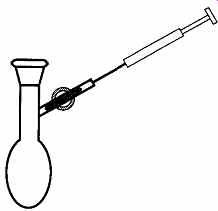
FIG. 21 I f the plug is opened, a syringe may be inserted into the stopcock
to dispense liquid.

Table 20 Requirements for Burettes
Like pipettes, Class A burettes have slower outflows than Class B burettes. They allow the user to better control the dispensing fluid. The slower speed also allows the liquid in the burette ample time to flow from the walls at the rate of the dispensing liquid. Thus the user does not need to wait before making a reading.
A burette should be mounted securely in a vertical position with a burette clamp or several three-fingered clamps. A single three-fingered clamp is likely to wobble and swing off vertically. If the accuracy of your work is critical, a plumb is recommended to achieve a true vertical orientation.
A burette can be filled from a side tube or three-way stopcock on the bottom. If there is no bottom-filling capability, the liquid can be poured into the top of the burette with a funnel. If any liquid spills on the outside of a burette, wipe the burette dry with a laboratory tissue.
Unless a burette is automatic and one wishes to fill to the 0.00 mL mark, overfill the burette about 10 mm past the zero line. Let the liquid settle a minute, then release some of the liquid into a beaker or some other receptacle by slightly opening the stopcock. Let the fluid lower to the zero line. Wait another minute to allow the fluid to settle to the new level, and re-check the level of the meniscus at the zero line. Release or add more liquid as necessary.
To make a burette reading, first read and record the liquid volume in the burette, dispense the required amount, and reread the liquid volume in the burette. Then subtract the first reading from the second reading to calculate the amount of fluid delivered. Self-zeroing burettes do not require a first and second reading, because all readings start from 0.00 mL.
3.14 Types of Burettes
There are four types of burette designs. Not every type of burette design is made in all tolerances, and some burettes have limited use.
Some burettes have a tube for easier filling attached between the calibration lines and above the tip. Flexible tubing is attached to the tube used for filling the burette. There are two methods to stop liquid flow. One technique uses a pinch clamp on the flexible tubing, and the other has a stopcock on the side tube. The pinch clamp can lead to inherent errors as the pressure from the weight of the liquid in the burette causes a small expansion of the flexible tube. As the burette is emptied, this pressure decreases, and the amount of error decreases as well. If your work requires limited accuracy, these changes are well within tolerance.
Alternatively, a stopcock can be used instead of a pinch clamp. There are no hydrostatic complications with the stopcock.
[The three-way stopcock receives its name because it has three arms leading to the barrel. A two way stopcock has two arms leading to the barrel.]
The least accurate burettes are Mohr burettes (see FIG. 22). Mohr burettes do not have stopcocks at their tips and therefore require flexible tubes with pinch clamps to control dispensing liquid.
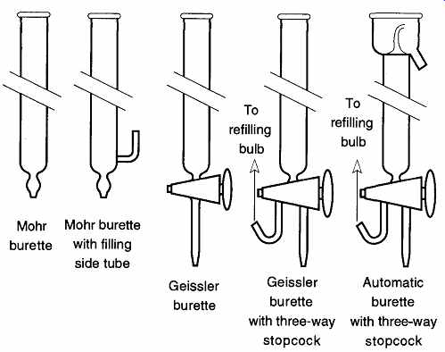
FIG. 22 Different types of burettes.
The standard lab burette is the Geissler, which can be identified by the stopcock at the bottom. It can be refilled by pouring liquid in at the top or by a filling tube from the side. Some Geissler burettes provide three-way stopcocks for easier filling (see FIG. 22). If the stopcock is turned one way, the burette fills, if it is turned 180°, the burette empties.
A third type of burette is the automatic, or self-zeroing, burette. It can repeatedly be filled quickly and easily to exactly 0.00 mL, meaning that to make a measurement, no arithmetic is required to determine the amount dispersed. This method of dispersing liquid is not only a valuable time-saver, it can help avoid errors due to poor arithmetic. The self-zeroing burette is filled by intentionally overfilling the top which is enclosed and has a drainage for collecting the overflow (see FIG. 22). The top portion of a self-zeroing burette is not calibrated, so if you dispense less liquid than is contained in this region, there is no way to determine the amount removed.
The last type of common burette is the dispensing burette. It is easy to recognize by its size. It can carry up to one liter of liquid and is capable of fast, effective liquid dispensing. Its accuracy is about ±0.5% of total volume.
3.15 Care and Use of Burettes
Burettes are very seldom tip- or end-heat strengthened as are pipettes, and they are therefore more prone to chipping or cracking. Burettes with removable tips and/or stopcocks can be useful for salvaging burettes that otherwise would be thrown away. Because the burette's calibration is exclusively on the column, removable tips and stopcocks have no effect on the buret's tolerance quality, nor should they imply the level of quality.
In addition to tip care, the care of stopcocks on a burette is equally important.
They should not jam, leak, or provide inconsistent release of fluids.
Glass stopcocks on burettes are prone to more wear than stopcocks on other lab oratory apparatus due to the conditions under which burettes are used. Therefore, it is important to periodically remove the glass plug of a burette's stopcock, clean the plug and the barrel, and re-grease it. The removal of the old grease is critical because it may carry particulate matter that can scratch a stopcock plug.
It is common for an old burette (that was working well) to leak if the original plug is lost or broken and is replaced with a new plug. This leakage is because the old plug and barrel wore together and evenly. The new plug is not worn with depressions that match the depressions on the old plug. Regrettably, the best recourse may be to replace the entire stopcock or to discard the entire burette.
Regrinding can be done by a trained person, but ultimately, you once again will have a matched plug and barrel.
It is not always possible to successfully take the plug out of one glass stopcock and place it in the barrel of another burette made by the same company. However, it is just about impossible to do such a switch if the brands are different. Although either plug will fit in the barrel, it is unlikely that the holes will line up and fluid will be unable to pass by the plug. Anytime you place a plug into the stopcock barrel of a burette, sight down the burette tube and see if you can see the hole of the plug (see Fig. 3.17). If the hole is offset, or not in sight, try a different plug until a good match is found.
If you suspect that a stopcock is leaking, remove all grease (if present) from the stopcock, and replace the plug (which should be wet with water) ungreased into the barrel in the closed position. Push the plug in firmly, but do not rotate the plug (if the plug is glass, rotation without grease may jam the plug in the barrel). Next, fill the burette with water and see the rate of water loss over a period of about a half-hour. If the water drops more than 3 mm in length, the stopcock can be considered poor. If there is no significant loss, pull the stopcock out, rotate 180°, replace, and retest. Any loss of water less than 3 mm will easily be assisted by the application of grease. However, any attempts to repair a leaky stopcock by extra grease will be doomed to failure. Adding excess grease to repair imperfections in a stopcock is like adding extra lacquer to fill up the rough surface of unsanded wood: It just does not work. Regardless, the excess grease is likely to fill the plug hole, resolving the leaking problem in an unacceptable manner.
How often you need to clean and re-grease a stopcock depends on the quality and type of grease you are using, how often the burette is being used, and the nature of the fluids within the burette. It is safe to say that an inexpensive grease will require cleaning and replacement more often than a grease of higher quality.
Do not use silicon-based stopcock grease on burettes unless the nature of your chemicals absolutely requires it. The reason is that silicon-based greases require constant cleaning and replacement to maintain their slippery nature. Also, the most effective way to clean silicon grease is with a base bath. However, the base bath is considered one of the two worst cleaning methods for use on volumetric ware. Silicon grease may be inexpensive in the short run, but it can prove to have many hidden costs. If the chemicals in your work require you to use silicon grease, it would be better to use a Teflon stopcock or rotary valve as a substitute.
They are a much better choice because they do not require any grease and require very little maintenance.
The plugs from Teflon stopcocks and rotary valves must be protected from scratches. So, when a stopcock is disassembled for cleaning, lay the plug down where it is not likely to be scratched or pick up paniculate matter. Wipe the plug with some methanol (or acetone) on a Kimwipe before reinserting it into the stop cock or valve barrel. Be sure to follow the correct sequence of end pieces when reassembling the stopcock: The sequence is (white) washer, (black) O-ring lock washer, and (colored) plastic nut (see Fig. 3.21). If the washer and lock washer are reversed on a Teflon stopcock, the plug will tighten as you rotate it clockwise (CW), and loosen (and probably leak) as you rotate it counterclockwise (CCW).
When storing burettes with stopcocks, leave the locking nut on a Teflon stop cock loose. Then, if the stopcock gets warm, the swelling Teflon plug is less likely to swell and stick, or split the walls of the barrel.
Do not store solutions in a burette, and never store alkaline solutions in a burette. Alkaline solutions will react with the glass and cause a glass stopcock to freeze. Also, an alkaline solution will react with the glass, creating a rough surface which can scratch a Teflon plug.
The procedure for cleaning burettes is similar to general glass cleaning already discussed. Because burettes are only used to deliver, it is never necessary to dry a burette before use. However, a wet burette can change the concentration of the solution being placed within it. To avoid changing concentrations, shake the burette dry and pour a small amount of the solution you will be working with into the burette. Swirl and/or rotate it around the burette, and pour it out. If you have a very low molarity solution, you may want to repeat this process again. The pre rinse (with the solution to be used) will reduce, and should eliminate, any change in concentration caused by standing water in the burette.
When first filling a burette, any air bubbles in the tip region (below the stop cock) should be removed. If a bubble remained where it originally was, there would be no problem. However, if a bubble comes out while making a measurement, it takes the place of fluid that was recorded, but never left the burette. The standard practice for removing bubbles is to overfill the burette, and open the stopcock fully to try and force the bubble out. This technique often works, but it can also be wasteful of material.
An alternate method of tip bubble removal was reported by Austin.
First, pour about 1 mL of fluid into the burette, open the stopcock to let the fluid into the tip region and close the stopcock. Now observe the tip and see if a bubble is trapped within the liquid of the tip. If there is no bubble, fill the burette to the top and proceed with your work. If there is a bubble, turn the burette so the stopcock is on top and quickly rotate the stopcock plug 180°. This procedure will lower the liquid in the tip of the burette, but if done quickly enough, it should not empty the tip. It should, however, remove the bubble from the tip region. The advantage of this approach is that it uses less solution.
4. Weight and Mass
4.1 Tools for Weighing
We weigh things by comparing the unknown weight (or force) of an object with a known weight (or force). The device used to weigh things is called a balance. The word comes from the Latin bilancis, or two dishes. The word balance is still used despite the fact that two-dish (or two-pan) balances are seldom (if ever) used nowadays. In lieu of a second pan, the counter (opposing) force now may be springs, built-in calibrated weights, or a magnetic device called a servomotor.
There are four classes of balances, each based on their ability to split hairs as it were, or, more specifically, based on the number of intervals used within the scale capacity. For example, if a laboratory balance has a capacity of 200.00 grams and it reads to two decimals, it would have 20,000 scale intervals. The formal identification of four classes was devised by the International Organization of Legal Metrology (OIML), and they are shown in Table 21.
Balances can be calibrated or verified for accuracy with special weights, called calibrated weights, whose specific mass is known. Calibrated weights* vary in quality and tolerance. They are classified by type, grade, and tolerance. All calibrated weights are compared directly or indirectly to the international prototype one-kilogram mass to verify their accuracy.
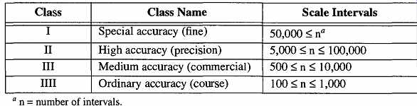
Table 21 Classifications of Weighing Equipment
4.2 Weight Versus Mass Versus Density
It is fair to say that an object weighing a ton is heavy and that few, if any, people could move or lift it. However, on the moon the same object would weigh only a bit over 300 lb-although the average person would still be unable to move the object. If we were on the space shuttle in a free-fall environment, anyone could move the object around with relative ease. When we weigh an object, we are measuring its inertia to Earth's gravitational pull. That measurement is its weight, not its mass. The weight of an object, not its mass, will change depending upon its inertia.
Unlike weight, which varies relative to its inertia (such as gravity), mass is an inherent and constant characteristic of any object. In any given gravitational environment, an object with a lot of material (mass) will weigh more than an object of the same type, but less material. Because of this quality, we can make calculations of, and about, an object's mass from its gravitational weighing.
[Calibrated weights are verified to weigh what they say they do within a given tolerance. The smaller the tolerance of a calibrated weight, the better the quality and the more expensive it will be.
These parameters are discussed further in the section on calibrated weights .]
Density is not directly related to mass or weight, but is calculated from an object's weight divided by its volume (g/m^3). For example, a large object of little mass (such as foam rubber) is considered to have little density. On the other hand, a small object of tremendous mass (such as a neutron star) has tremendous density. Density refers to the amount of space ("volume") a given amount of mass occupies. Mass refers to the amount of material in an object, not to the amount of space it occupies.
In everyday parlance, we imply an object's mass when we speak of its weight.
However, because we weigh an object based on its attraction to Earth, we are, in effect, measuring its force. In a nutshell, we measure an object's force to obtain its weight, from which we can calculate its mass. The validity of this approach holds despite the fact that the force of gravity varies over the earth's surface by over 5% in addition to changes in elevation.
4.3 Air Buoyancy
The fact that weights occupy space creates an interesting problem. The space occupied by a weight is normally occupied by air, and because air has weight, it provides a buoyancy effect (known as Archimedes' principle) against the real weight of the object. This effect influences the measured weight of an object.

Table 22 Variation in Weight with Atmospheric Density
The problem is more easily explained by examining what happens when you place something in water (because water weighs more than air and provides a greater buoyancy effect, its effects are more dramatic). If you put a cube of metal in water, it sinks to the bottom of the container. That cube weighs less in the water than it did in air, by an amount equal to the weight of the water it displaced. On the other hand, if you put a similar-sized block of wood in the water, it would float because the amount of water that the wood displaces weighs more than the wood, preventing the wood from sinking. The same phenomena occurs in air, which is why helium balloons rise and wood balloons fall.
Even if an object's density and size change, its mass does not. Thus, it is possible for two objects to have the same mass but weigh different amounts due to the effects of air buoyancy caused by the weight of air. This principle can be demonstrated by taking a calibrated weight whose density is 8.0 g/cm^3 and weight (in air) is 100.000 g, then using it to weigh an equal weight of pure water whose density is 1.0 g/cm^3. Because their densities are different, they will occupy different volumes of air: Their volumes are 12.5 cm3
and 100 cm3 , respectively. If you were to weigh each object in a vacuum to eliminate the air buoyancy factor, the calibrated weight would now weigh 100.015 g and the pure water would now weigh 100.120 g.
Factors that affect buoyancy are the density of a sample, ambient air pressure, and relative humidity. Thus, a barometer and humidity indicator should be located within any balance room where highly accurate readings are required. The counterbalance weights within single-pan balances are also affected by air buoyancy, but in equal amounts to the sample, so they should cancel each other out. The exact amount of the buoyancy effect varies depending on the density of the material being weighed and the density of the air at the time of weighing. This phenomenon was studied in detail by Schoonover and Jones, and by Kupper.
The formula for converting a weighing result to true mass is given in Eq. (eqn. 1):
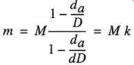
(eqn. 1)
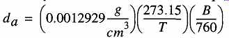
(eqn. 2)
There are only two occasions where measured weight equals true mass, when it = 1. This occasion occurs when measurements are made in a vacuum or the density of a sample is equal to the density of the mass standard. Fortunately, the greatest differences only occur when an object's density is particularly low (0.1% for density =1.0 g/cm^3 and about 0.3% for density 0.4 g/cm^3). In most situations, the effect of air buoyancy is significantly smaller than the tolerance of the analytical balance. The effects of varying densities (of objects being weighed) and varying air densities are shown in Table 22.
One approach to avoiding the problem of air buoyancy is to weigh an object in a vacuum (known as "weight in vacuo"). Such readings provide an object's true mass as opposed to its apparent mass. There are a variety of vacuum balances made precisely for this purpose. However, vacuum balances are expensive, require expensive peripheral equipment (such as vacuum systems), and are neither fast nor efficient to use.
4.4 Accuracy, Precision, and Other Balance Limitations
The amount of accuracy required in a balance, like most things in the lab, depends the balancing of your needs versus the capacities of your pocketbook. You do not need great accuracy if all you are doing is weighing letters. On the other hand, weighing volumetric flasks to calibrate volume requires tremendous accuracy. Not only is the cost greater for a more accurate balance, but the support equipment and personnel for the maintenance of such equipment are also greater. When analyzing the different attributes and characteristics that help to define the quality and capabilities of balances, many different terms are used. The following terms (and concepts) are used to describe various features of all balances:
The greater the accuracy of a balance, the closer the balance will read the nominal weight* of a calibration weight. If the calibration weight reads 10 mg, the balance should read 10 mg. If, for example, the balance reads 10.5 mg, it has less than desirable accuracy, and if it reads 12 mg, it has poor accuracy.
The precision of a balance is related to how well it can repeatedly indicate the same weight over a series of identical weighings under similar environmental conditions. Precision is not a measure of how accurately a scale can make a single weight reading. The index of precision is the standard deviation for a collection of readings. If the index of precision is greater than the readability of the balance, accuracy is significantly jeopardized.
[The nominal weight of a calibrated mass is the calibration that is printed on, or stamped into, its surface.]
Readability refers to the smallest measurement that a balance can indicate and that can be read by an operator when the balance is being used as intended. Generally, triple-beam balances have a readability of ±0.1 g, centigram balances have a readability of ±0.01 g, and analytical balances have a readability of ±0.0001 g.
Neglect or abuse can damage a balance resulting in no deflection for the original smallest units. The result is a change in the readability for the damaged balance to a new, and larger, value.
Linearity is the ability of a balance to accurately read the entire range of weights that it was designed to weigh. A balance which accurately weighs 10 mg, but poorly weighs 100 mg, but again accurately weighs 200 mg on up to its full-scale calibration, is said to have poor linearity.
Off-center errors are problems specifically associated with top-loading balances. Placing a balance pan above the fulcrum places different torques and friction on balance pieces that do not exist when a balance pan hangs. The problem is exhibited if an object has different weight readings when moved to various locations across the surface of a top-loading balance pan.
Accuracy is the ability of a balance to precisely and repeatedly read a weight.
The ability for a balance to read a particular weight is based not only on the above attributes and characteristics, but also on three other factors:
1. The quality of the machine
2. The quality of the weighing process conditions [typically dependent upon the balance's location]
3. The skill of the person operating the balance Each of these factors is dependent on the other two, and the failure of any one of them can affect the accuracy of a weighing. For example, do not expect great accuracy from a balance that is located above a radiator. Likewise, do not expect accuracy from a balance which has just demonstrated poor precision. Finding the source of errors in weighing is a step-by-step process. You must rule out each problem before moving on to the next level.
4.5 Balance Location
By their nature, balances are fragile pieces of equipment. The more sensitive a balance is, the more susceptible it is to environmental influences. The following should be considered before placing permanently in any location:
1. Balances should be away from sources of vibration. Rooms used for balance work should be away from elevators and ventilation motors.
They should be located near support walls (as opposed to walls that just separate rooms), which can help dampen vibration. To observe the amount of vibration your balance is receiving, lay small dishes of water at several locations on the supporting table you plan to use and float microscope cover slips on the surface of the water in each dish.
Shine a light on each cover slip in turn, such that the light is reflected onto an adjacent wall. Make observations over several times during the day. Have someone walk around the room, close or open the door, and perform other activities that may cause vibrations. The more stable the light's reflection, the better the table (and location) will be for weighing purposes.
2. Balances should be away from winds and drafts. Many buildings have sealed windows, but vents can generate drafts as well. Although fume hoods generally do not create a significant draft, opening and closing doors can.
3. Balances should be placed away from sources of varying temperature, including direct sunlight, windows, heaters, vents, drying ovens, refrigerators, doors, and rooms on the south side of buildings.
4. Balances should be kept away from rapid changes in humidity such as those that occur when steam heaters are used. Not only will steam heaters affect temperature, the change in humidity can affect the workings of the balance.
5. Balances should be kept away from stored chemicals, especially those with low vapor pressures. Because most of the internal workings of modern balances are not in plain sight, you will not be aware of any corrosion until the balance begins to malfunction. At that point, it may be too late to remedy the situation.
6. Hanging balance pans should be removed before balances are moved from one location to another to take the strain off the beam balance points as well as to prevent a swinging pan from damaging the balance.
7. Balances should be recalibrated after they have been moved.
8. Balance rooms should be maintained free of dust. Dust can affect both mechanical and electronic balances.
9. Balances should be placed on nonmagnetic, nonferrous surfaces.
Cement, stone, and wood are all acceptable.
If, after reading these rules, you conclude that the best place for a balance is in a special room by itself, you are right. Such a room ideally should be windowless, with one separate, shielded entry and filtered, baffled vents. The room should be small, with support beam walls and very heavy benchtops, and should be maintained consistently at 20°C.
In lieu of a perfect room, the specific problems your room presents should be known to protect the validity of your weighing as much as possible. For example, if you are having problems limiting your vibration sources, make your weighings at odd hours when elevators are not in use or when people are unlikely to enter the room. For drafts, baffle vents, place screens around the balance, or use other similar stop-gap measures.