AMAZON multi-meters discounts AMAZON oscilloscope discounts
<< cont. from part 2
1.14 Storing Glass
When not in use, glassware should be cleaned and put away. Glassware that is scattered on benchtops and out in the open clutters working areas, is easily broken, will not stay clean, and, if dirty, may be confused for clean glassware. In other words, glassware that is not cleaned and put away is a toxic and/or physical danger that is likely to undermine and potentially negate any viable research.
There is a phenomenal amount of wasted glassware and research solely due to glassware that was not cleaned and put away. The techniques of cleaning glassware are discussed in Section 4.
Once cleaned, glassware should be dried before it is placed in storage. If possible, a section in your lab should be reserved for cleaning and drying glassware so that you (1) do not contaminate glassware with cleaning materials, and (2) do not have glassware that is drying be in your way.
The best place to store laboratory glassware and equipment is in covered or enclosed storage areas. Open shelving and other areas where dust can settle on (and in) apparatus should be avoided. Glass enclosed storage cabinets are excel lent as they provide opportunity for visual inspection of available items and reduce unnecessary door opening. Place strips of tape across large glass doors to prevent accidents by people who may not see the glass.
The most common place for glassware to be stored is in a drawer. Drawers pro vide many of the recommended requirements for glassware and equipment storage except visibility. In fact, a drawer's biggest liability is that it can be opened and closed quickly by someone trying to locate a particular item. The rattling of glassware rolling into other glassware or apparatus portends glass repair.
There are several ways to protect glassware stored in drawers:
1. Label all drawers. Self-sticking labels are sufficient for most labs. How ever, if the contents of the drawers are constantly being transferred, metal or plastic card holders may be more practical.
2. Encourage users of the lab not to jerk drawers open or slam them shut. I do not know of any way to prevent these actions, but continued abuse may be thwarted by demanding financial remuneration of broken glassware (if the culprit is caught).
3. Limit free movement of glass items, (a) Small items should be kept in small boxes with cut-off tops (to facilitate observation of the con tents), (b) Line drawers with plastic mesh or plastic bubble packing material to limit movement as well as cushion impact against the walls of the drawer, (c) Be sure to prevent items from twisting or tilting within the drawer. Such movement may cause part of an apparatus to stick up and either prevent the drawer from opening or be broken off (if the drawer opener is strong and persistent).
Nesting glassware is a good space saver, but be sure there is adequate room for the glassware to nest. Evaporation dishes are not a problem, but the pour spouts of small beakers tend to wedge within larger beakers.
Obviously the best solution to prevent this situation from happening is to ensure adequate room for smaller beakers. A simple technique may be used to separate beakers. Squeeze the larger beaker at right angles to the jammed unit (see FIG. 9). It does not take a great amount of pressure, but you must remove the smaller beaker as you squeeze. For safety's sake, wear leather or Kevlar® gloves when squeezing glassware. Although the amount of flexure needed is very small, if there is a flaw in the right place, a piece could break in your hand.
Limit dust within glass items such as pipettes by plugging the hole with a Kim wipe or wrapping the ends in a Kimwipe held by a rubber band or tape. Do not tape directly on the glassware because it may be difficult to remove after the tape has aged.
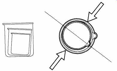
FIG. 9 Nesting beakers and removing stuck nested beakers.
1.15 Marking Glass
The permanent marks on glassware are made of a special type of a glass-ceramic that fuses onto glass surfaces above 500°C. They are applied either by a silk screening process or by decal. Ceramic decals are permanent and will resist most chemical attack. They are susceptible to chemical attack by alkalis and hydrofluoric and perchloric acid, all of which can remove the markings.
Old glassware is used to provide a frosted circular spot for marking the glass.
This frosted zone was easier to write on than the ceramic spot, but cost more to manufacture than simply adding a ceramic decal spot as part of the ceramic numbering that is placed on already. The frosting added one more step to the manufacturing process, and therefore it was phased out.
The ceramic white dot on most glassware can be written on by pencils for identification. Although it is not easy to write on glass, there are five techniques that allow one to identify and mark on glass:
1. Alcohol-based pens. These pens, usually fiber-tipped, can write on most surfaces and are water-resistant. They can be removed with any hydrocarbon solvent and will burn off in a drying oven. Although they are not likely to smear from the glass onto fingers, they may. These pens can quickly dry out if not recapped after use. They are available in a variety of colors.
2. Waxed pencil. Like a crayon, waxed pencils can easily write on glass and are subject to the same removal techniques as alcohol pens. They are likely to smear onto fingers and other equipment. They are avail able in a variety of colors.
3. Soft pencil. The company Schwan - STABILO GERMANY makes a line of pencils that are identified as "All-STABILO." These pencils are so soft they can easily write on glassware. The markings from these pencils can withstand high heat (600 to 700°C) but can be wiped off by the rub of a finger.
4. Titanium writing. Titanium dipped in water (or writing on wet glass) will leave a permanent marking on glass. Although admittedly the markings are not easy to see (only ~ 0.25 mm wide*), they are impervious to hydrocarbon solvents and can resist temperatures up to 1500°C. The markings can be removed with nitric acid.
5. Self-adhesive labels. This method is sort of cheating because you are not writing on glass. Rather you are writing on labels stuck to the glass. The labels can be written on by standard pens and pencils, then placed on any type of glassware. Because they are available in different colors, the labels can assist in separating glassware by type, then specific identifying information can be written on the labels. It is possible to remove these labels by lifting them off, but sticky residue may remain. The residue may be removed by acetone. If you write on the label with an ink pen, the ink may smear or bleed if chemicals leak onto the label.
[*The width is related to the amount of contact surface the titanium has with the glass. ]
1.16 Consumer's Guide to Purchasing Laboratory Glassware
Laboratory glassware can be expensive. As far as the user is concerned, the chemistry of the glass by the three major companies is equally good. However, considerable ranges of quality can be exhibited in glass quality and items made out of a particular glass. If a glass or the products made from that glass are not acceptable, do not accept the item(s).
Glass companies do not try to make poor-quality glassware, nor are they intent on selling their mistakes. However, mistakes happen and sometimes the mistakes get by quality control. Regardless, the final quality control person is the customer.
If you receive poor-quality glassware, by working with your supplier and/or the glassware manufacturer, the problem can be resolved.
Faults in glass can include the following:
1. Seeds* are like specs of sand in a glass that did not properly melt. They are particularly susceptible to thermal strain that would not affect regular glass.
2. Bubbles are trapped air within glass. These are more visual than structural problems.
3. Airlines are bubbles that got stretched during the manufacturing pro cess. These are more visual than structural problems.
4. Blisters are bubbles that are very close to the surface and are likely to break open. If they partially break open, they may hold liquids or particulate material that can contaminate current or future work.
5. Cords are glass inclusions of a bad melt. They may appear like sections or spots of glass that did not properly melt.
6. Chill mark is a wrinkled surface caused by poor forming in a construction technique called "mold pressing." The bases of graduated cylinders and the bodies of funnels are typically made with this process.
This is more of a visual imperfection and does not imply poor manufacture.
There are more companies that make glassware than make glass. Each is dependent upon the glass manufacturing companies to provide glass with a minimum of the problems mentioned above. Ideally, such glass flaws are sorted out before or during the manufacturing process. In addition, there are flaws that can be created during the manufacturing or shipping of glass items. Ideally these problems should be caught before reaching the consumer. However, because a number of manufacturing processes are automated, errors in production may not be caught until complaints start to come in from the field (i.e., you).
[*This flaw can become a focal point for fracture.]
No manufacturer can be considered totally dependable. Some manufacturers make some products better than other manufacturers, and they make some items better than other items. Therefore, in addition to the flaws that can be found in glass as just listed, do not accept the following flaws in manufactured glass items:
1. Chipped, scratched, or cracked glass out of the box. There are ample opportunities for these flaws to happen in any lab, so you do not need an early assist from the manufacturer, the warehouse, or the shipper.
Because any of these three may be equally culpable in causing physical damage, it is best to not assume who might be to blame. Let the supplier worry about it.
2. New stopcocks or joints that leak. Do not "repair" them by adding more stopcock grease than should normally be required. Such practice can easily exacerbate the problem and cause other problems as well. However, before you complain, be sure that pieces are assembled correctly and that matching parts are assembled with their correct pairs.
3. Seals with folds and/or large quantities of internal bubbles. When glass is first attached to other glass, it will show folds, or ripples, that need to be worked smooth. Sometimes in production, speed overtakes quality and these flaws are not adequately worked out. These folds can be weak spots requiring little stress for fracture. One approach a glassblower may use to speed the "working out" of these folds is to use a hotter-than-necessary flame. If the glass is inadequately cleaned (another victim of production speed), the intense heat will cause the glass in the region of the seal to develop many bubbles. These bubbles contribute to (and are an indication of) weak glass. Although many seals may have bubbles, it is the overabundance of bubbles that should elicit concern.
4. "Burnt" glass. The "burning" of glass is caused by severe overheating of glass during glassblowing operations. This process removes some of the component materials. Because this new glass has a different chemical composition than the glass it was made from, it cannot flow or mix properly with the surrounding glass. It can be identified by a spot of glass that does not look as though it has properly fused with the surrounding glass and may be confused with a fold.
2. Flexible Tubing
2.1 Introduction
There is an enormous variety of flexible tubing available for use in the laboratory because no single tubing type or size is right for all purposes. Within most laboratories, flexible tubing is used for such purposes as connecting vacuum systems to mechanical pumps and manometers, transferring nitrogen or argon gas around the lab, and connecting water lines to condensers, coolers, and constant temperature baths. In addition, you may connect a source for natural gas (or propane) and oxy gen to a torch and even temporarily connect a mechanical pump to drain used pump oil.
Comparing the various brands and types of flexible tubing is not unlike comparing a variety of stereos at competing stores. Because of the many different brands and models of tubing available, and because not every manufacturer uses the same analysis parameters, a cross comparison of features (or prices) from one type of flexible tubing to another is very difficult.
Purchasing flexible tubing has a few other complications. First, few laboratory supply house catalogs identify the manufacturers of the tubings listed. Further more, just as stereo stores do not carry all brands of stereos, no single laboratory supply company carries all manufacturers' tubing. Therefore, if a particular type of tubing has features that you require, you may need to ask your laboratory sup ply house if it carries (or can obtain) a particular manufacturer's product. This section will detail the differences and similarities between the types of tubing that may be used in the chemical laboratory.
Flexible tubing is identified by its inside diameter and wall thickness (see FIG. 10). This identification is unlike glass tubing, which is identified by its out side diameter and wall thickness. When ordering flexible tubing, specify the inside diameter and the wall thickness.
When ordering tubing, size is only one of several variables to consider. Two others are the tubing's physical characteristics (see Table 4) and its chemical resistance properties (see Table 5). Table 6 compares some of the advantages and disadvantages of the various types of flexible tubing.
IMPORTANT NOTICE
Unless otherwise stated, all data in this section (test conditions) are based on tubing that has 1/4" I.D. and 1/16" wall thickness.
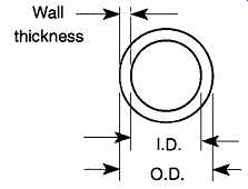
FIG. 10 The measurements of flexible tubing.
2.2 Physical Properties of Flexible Tubing
The following physical characteristics may be important in your selection of flexible tubing (see Table 4).
1. Color and/or Transparency. If it is important to see a solution flowing through tubing, then transparency or translucency of the tubing is important. Color cannot be used as an indicator of physical properties or chemical resistance. Color can be used by manufacturers to distinguish between various tubing types however. For example, the manufacturer of Nalgene® tubing uses blue imprinting on its clear tubing to designate its 8000 line of tubing, red imprinting to designate its 8000 vacuum line, and black imprinting to designate its 8007 line of tubing. Color can also aid in laboratory setup. For example, labs that use color to identify operations may use orange tubing for natural gas, green tubing for oxygen, blue tubing for water going into a con denser, and red tubing for water leaving a condenser.
2. Durometer Range. The durometer range is a measure of a tubing's physical hardness, which is indirectly related to the tubing's flexibility and resilience. The harder a tubing's composition, the less flexible and resilient it is likely to be. The hardness of tubing material is calibrated with an instrument called a durometer. The durometer is a device that measures the amount of reflected bounce by a special hammer off the material being tested. Most tubing is tested using what is called the Shore A technique. When very firm tubing is tested, the Shore D technique is used. Shore D measurements can be interpolated to provide approximate Shore A measurements for comparison.
For simplicity's sake, I have chosen to interpolate all Shore D measurements to Shore A. Except where advised to the contrary, please assume that all durometer readings preceded with a "=" symbol are Shore D measurements that have been interpolated to Shore A.
3. Flame Resistance. Some tubing materials are naturally resistant to flames, while others are flammable to various degrees. This quality must be considered if the tubing may be exposed to a high, or direct, heat source. Unfortunately, although we know that a given tubing may be flammable, flame-resistant, or nonflammable, there is no information currently available by which one can quantitatively com pare the flammability of tubing.
4. Flexibility. Is the tubing flexible or stiff? Is the tubing prone to kinking? Transport of gases or fluids may be impaired by nonflexible tubing.
5. Gas Impermeability. The permeability of tubing depends on the gas being used: Tubing that is fine for nitrogen may be totally unacceptable for helium. Unfortunately, comprehensive data on the permeability of various gases through tubing are not readily available. In most cases, it is necessary to contact the manufacturer for information.
6. Resilience (Memory). Over time, some tubings mold themselves to new shapes, whereas others will always return to their original shape. For example, rubber has the best resiliency of any tubing, and thus can maintain a constant grip on a hose connection. On the other hand, Tygon® tubing, which is not very resilient, will "learn" the new shape of a hose connection and will eventually lose its grip on the nipple.
Internal pressure (i.e., water pressure) on a non-resilient hose can cause it to slip off its connection. Low-resilience tubing should be attached with screw clips (see FIG. 11), for a more secure attachment.
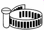
FIG. 11 A typical screw clamp.
7. Temperature Range. As temperature increases, a tubing's ability to withstand internal pressure decreases. Conversely, if the temperature drops below the recommended temperature range, a normally flexible tubing may crack when flexed.
8. Vacuum. Under vacuum conditions, thin wall tubing will collapse. In general, it is safe to use tubing for vacuum work if the tubing satisfies Eq. (eqn. 6). However, heat may cause this equation not to hold up:
ID. < 2 x wall thickness (eqn. 6)
In many labs it is standard to use red heavy-wall rubber tubing to connect mechanical pumps to vacuum systems. However, there is no technical reason for using red (colored) tubing. Any tubing that meets the qualifications for vacuum work (or your specific vacuum work) should suffice, regardless of color.
Pressure. There are many variables that interact to affect the maximum potential pressure tolerance of any given tubing. These include:
1. Inside Diameter: The smaller the I.D., the greater the potential pressure tolerance.
2. Wall Thickness: The greater the wall thickness, the greater the tolerable pressure.
3. Temperature: The higher the temperature, the less the tolerable pres sure.
This statement does not necessarily mean that the lower the temperature, the greater the tolerable pressure because at very low temperatures, tubing becomes brittle and prone to failure.
4. Time: If you are working over the recommended pressure, it is only a matter of time before the tube will burst.
5. Material Transmitted: Most types of tubing can handle most materials for at least a short time. However, if tubing is undergoing chemical attack, the tubing will eventually fail.
6. Braiding: Internal or external braiding provides extra strength for pres sure systems.
7. External Surface. If you wear gloves and/or work in a glove box, you may want a tubing with friction rather than a smooth and/or slippery surface. To improve its handling capabilities, natural rubber tubing is sometimes cloth-wrapped during the curing process. Once the curing process is completed and the cloth is removed, the cloth impression remains on the tubing, providing a better grip.
2.3 Chemical Resistance Properties of Flexible Tubing
A tubing's resistance to chemical attack depends on the nature, quantities, and length of time it is exposed to particular liquids or gases. Some tubing manufacturers have tested their tubings against a variety of chemicals and gases. Some manufacturers have even made these studies at various temperatures. The Nalgene Corporation has listed the effects of many chemicals on a variety of its polymers, and this list is included in Section B. If you have a question about the resistance of a particular type of tubing to a given material, contact the manufacturer. How ever, remember that there are many possible combinations and permutations of chemicals. Unless you are sure that a given chemical is not likely to affect your tubing, it is best to test the tubing with the chemical in an environment that duplicates your conditions. Then you can properly determine if your system, setup, and/or chemicals will affect your tubing (or vice versa).
If in doubt, test it!
In general, the following materials are those you should consider to be potential reactants with flexible tubing:
- Acids (weak) Oils
- Acids (strong) Organic solvents
- Bases (weak) Oxygen
- Bases (strong) Salt solution
Table 4 Physical Characteristics of Flexible Tubing

Table 5 Chemical Resistance Characteristics of Flexible Tubing

Table 6 Comparison of Flexible Tubing Characteristics
3. Corks, Rubber Stoppers, and Enclosures
3.1 Corks
Cork, a thick, lightweight product from a Mediterranean oak, has been used in the laboratory for years in many ways. Typically, it is used as seals for glassware, as rings for supporting round-bottom flasks, and as sheets to protect surfaces from impact shock. Despite the incredible variety of plastics and other elastomers avail able, cork is still the material of choice for many operations in the laboratory.
Corks (stoppers made from cork) are still widely used to cap many materials within glassware. They are essential when storing organic solvents or other materials that could react with rubber stoppers. Each cork typically fits several different size tubes. An examination of various cork sizes is displayed in Table 7.
Corks are graded into five levels of quality: X, XX, XXX, XXXX, and Select.
The grades are an assessment of the number and degree of irregular cavities and cracks on the walls of the cork. Grade X is the lowest quality and Select is the highest. As would be expected, the better the quality, the more expensive the cork.
Regardless of the stated quality, always examine the integrity of the cork before assuming that it will contain your solution. Cork quality can vary significantly, even in better grades.
3.2 Rubber Stoppers
Rubber stoppers* are also efficient, simple, temporary system closures. Properly drilled, stoppers can support thermometers or funnels. Because new stoppers have no surface cavities or cracks, there is no risk of leaks as with corks. Like corks, stoppers are used to keep things in (or out) of container. Table 7 includes a list of rubber stopper sizes.
Stoppers, as opposed to corks, can react with a number of organic chemicals used in the laboratory. Likewise, a concern when using stoppers is that the closure not adversely affect the contained sample. For this reason, cork stoppers are often preferred when containing organic solvents. If you do not have any corks, you may use a rubber stopper that has been enclosed with an aluminum foil cover.
This technique has a few limitations: The covered rubber stopper will not grip into the seal (there is no friction to hold it in), and the crevices of the foil provide many potential small leaks.
Although rubber stoppers are normally intended for use with water-based solutions, do not use the aluminum foil technique with an acid or strong base solution because it will destroy the foil.
[Not all rubber stoppers are made of rubber. For simplicity, all elastomeric stoppers are simply being grouped into the catchall identification of "rubber stoppers."]
If you look in the average laboratory supply catalog, you may see listings for amber (or natural rubber), white, black, green, red, and/or clear stoppers. Ignoring the stoppers with premade single or double holes, there is not much difference between the first three-colored stoppers. The green and red/clear do provide some special characteristics.
1. Amber or Natural Rubber. These colored rubber stoppers are, simply, pure rubber. They are the most flexible of all the stoppers. There once was concern that sulfur in the stopper would affect catalytic reactions.
This concern is now unlikely because most stoppers should be peroxide-cured. If there is any question, check with the manufacturer.
2. White. These colored stoppers are essentially natural rubber stoppers dyed white.
3. Black. These colored stoppers are natural rubber stoppers with a mix ture of chemical agents and dyes to give black color. Black stoppers are somewhat more durable than natural rubber stoppers.
4. Green. These colored stoppers are made of neoprene (a synthetic rubber) and resist the deteriorating effects of oils better than natural rubber. Neoprene also has a wider temperature range than natural rubber.
These advantages come at a price, as neoprene stoppers are somewhat more expensive than the other stoppers.
5. Red or Clear. These are silicone stoppers and are somewhat harder than natural rubber stoppers. They are excel at high-temperature environments and meet FDA requirements. They are resistant to high-aniline point oils and chlorinated di-phenyls but are not recommended for most petroleum fluids, ketones, or water and steam.
3.3 Pre-holed Stoppers
Stoppers can be ordered with none, one, or two holes. As can be seen in Table 8, holes are sized according to the size of the stopper. One brand of white stoppers (Twistit®, made by the J.P. Stevens Co.) has three "pre-holes." You simply twist/ tear off small nipples on the bottom of the stopper to make the holes as needed.
Obviously, a hole of 3 to 5 mm cannot take a very large tube. In general, it is safe to insert a tube which is about 1 to 2 mm in diameter larger than the original hole size. As can be seen in Table 8, you can only insert 6- to 8-mm-diameter tubes or rods into the holes of size 2 or greater stoppers (about the diameter of the average glass thermometer).
If you find that the holes in your "pre-holed" stopper are the wrong size or in the wrong location, you can take a solid stopper and custom drill holes which meet your specific requirements. There are several techniques for drilling holes in stoppers, but regardless of the technique used, always start with a solid stopper.
Because rubber distorts with pressure, it is more difficult to alter a holed stopper than to drill a new hole. In addition, because elastomers distort and compress, drill hole(s) the same size (rather than slightly smaller) as the tubing you wish to insert.
This practice will allow easier insertion of the tube into the hole, yet will still pro vide a satisfactory leakproof seal. When the stopper is placed into its final location, compression from the container neck will further improve the seal.
Freezing and Drilling. Because of the flexibility and friction of rubber, it is essentially impossible to use a standard drill bit on a rubber stopper. However, if you freeze the rubber stopper in liquid nitrogen or pack it up in crushed dry ice, you can then drill a hole with a standard drill bit and drill press (or a machinist's lathe). Never hold the frozen rubber stopper with your hands while drilling. The stopper is extremely cold, and you will injure your fingers just by holding the rubber stopper. Furthermore, the rubber stopper may start to defrost during the drilling (the drilling friction will cause heat), or the rubber could grab the drill bit and spin out of your hand. It is equally recommended to use a drill press or machinist's lathe and not a hand-held drill. You cannot drill straight with a hand drill, and the potential for slipping is far too great. Be sure the drill bit is new or newly sharpened. Dull bits cause more friction, causing the stopper to heat up faster.
Drilling speed should be at the same slow speed used for plastics. Let the bit cut its way into the stopper by itself, and do not force the bit into the stopper while drilling.

Table 7 Comparisons of Cork and Rubber Stopper Sizes
When drilling rubber stoppers with a drill press, do not use a rag to hold the frozen rubber stopper. If the rubber grabs the drill bit, the rag could catch rings, watches, or other equipment. Leather gloves provide good protection and dexterity, and they should be used for all similar operations.

Table 8 Pre-drilled Stopper Dimensions
Using a Hand Cork Borer. A six-piece graduated set of hand cork borers (see FIG. 12) is relatively inexpensive, under $20.00 in brass and under $35 in steel.
If the bit is properly sharpened, a hand cork borer can make a fairly clean hole. If you are cutting into a rubber stopper, it is best to use a lubricant such as glycerin to keep the rubber from grabbing the borer. When selecting the proper bit to drill, use the cutting edge (the inside diameter), not the outside diameter, as a guide for selecting the proper boring bit.
Using a Motorized Cork Borer. See FIG. 13. Motorized cork borers can be relatively expensive (about $700) as compared to hand cork borers. However, if there is constant demand for custom-sized rubber stopper holes in your laboratory, it can be worth the expense. When selecting the proper bit with which to drill, use the cutting edge (inside diameter), not the outside diameter, as your guide for size.
Motorized cork boring requires a lubricant. There are two choices: glycerin, which is also used with a hand cork borer, and beeswax (or paraffin). To use bees wax, or paraffin, you must to momentarily press the cutting edge of the bit against the stopper so that the friction heats up the bit. Then, press a block of wax against the edge of the turning bit, allowing the melted wax to coat the drill. Now you can begin drilling the hole using an even, light to moderate pressure. After the bees wax cools and hardens, it can be easily picked off. Although it may seem like a bit more work to use paraffin than glycerin, it may be preferable because there is less to clean up afterward, the cleanup is easier, and the wax is less messy than glycerin. Glycerin can be wiped off with a rag, although some soap and water may be necessary for a more complete cleaning.
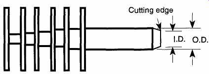
FIG. 12 A hand cork borer.
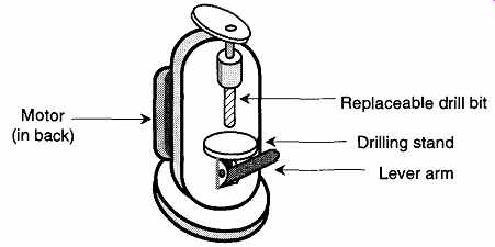
FIG. 13 Motorized cork borer.
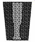
FIG. 14 An example of forced core drilling of a rubber stopper.
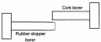
FIG. 15 Two different types of core bits.
Never force a bit through a stopper, but rather let a bit cut into a stopper on its own. It may be necessary to add more beeswax onto a bit while you drill. This addition can be made by extracting the bit from the stopper, pressing the block of beeswax against the bit, then continuing the drilling process. If you force the bit through the stopper, the resulting hole will lose its continuity and generally will decrease in diameter, as shown in FIG. 14.
When using a motorized borer machine on cork, use a cork bit that has an edge with saw blade teeth rather than a knife-edged rubber stopper bit (see FIG. 15).
This is especially true on small corks. A rubber stopper borer slices through the material, demanding that the stopper or cork expand to make room for the borer itself. Corks can't stretch (as can rubber stoppers) and tend to crack and split.
Larger corks are more likely to survive the stresses caused by a rubber stopper borer. On the other hand, cork borers chip away at the cork and remove the cork just as a saw removes pieces of wood as it cuts. The cork borer cuts its own path through the cork, allowing room for the borer, whereas the stopper borer requires the cork or stopper to squeeze around the borer. When selecting cork-boring bits, match the outside diameter of the bit to the piece you wish to insert. During the drilling operation, occasionally lift the blade up to help remove cork shards, other wise these shards will fill up the channel being cut and will make drilling difficult.
3.4 Inserting Glass Tubing into Stoppers
The most common reason to bore holes in rubber stoppers is to insert glass tubing.
Safe and proper techniques are simple and easy. Before inserting the glass, be sure that both ends of the glass tube are fire polished. Fire-polishing removes sharp ends or chipped edges. To fire-polish the end of a tube, place it in the flame of a gas-oxy torch (see the section on gas-oxy torches) and rotate the tube until the edge just starts to melt. Do not overdo it. If you let the tube remain in the flame too long, the end could close up. Because glass is a poor conductor of heat, the piece must be rotated while in the flame. Otherwise only one side will be softened and surface tension will cause it to sag in and distort. It may be possible to fire polish a small tube over a Bunsen burner, but it will take a long time for borosilicate glass to get sufficiently hot to melt. Tunneling (the transport of hot gases from the flame traveling down the tube, causing the tube to become excessively hot) can be prevented by placing a cork in the opposite end of the tube (see FIG. 16).
After fire-polishing a glass tube, let it cool before trying to place it in a stopper.
Do not try to speed up the cooling process by placing the tube under running water, because the rapid temperature change is likely to cause a crack on the newly prepared end.
Use some lubrication on the tube and rubber stopper. This lubrication can be glycerin, soapy water, or even plain water. Hold the glass rod close to the rubber stopper and keep the glass rod as short as possible. The preferable distance should be no greater than about three diameters of the tubing away from the rubber stop per (see FIG. 17). The longer the distance, the greater the torque that can be created. As the tensile forces increase, the chances increase that you will break the glass tubing. Use a rotating motion to guide (not force) the tubing into the stopper.
For safety's sake, wear leather gloves. Leather gloves are preferred because they provide a good amount of tactile control, a reasonable amount of friction, and excellent protection. A paper towel is not sufficient to meet any of these three criteria.
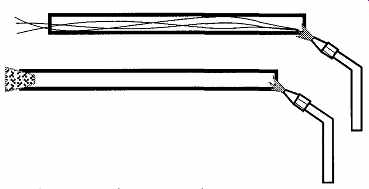
FIG. 16 Preventing hot gases from "tunneling" up a tube with
a cork in the end.
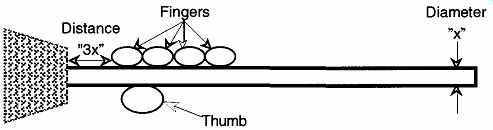
FIG. 17 Insertion of a tube into a rubber stopper.
3.5 Removing Glass from Stoppers and Flexible Tubing
After a glass tube has been left in flexible tubing or a rubber stopper for a period of time, it is typically hard to remove. The easiest and safest way to remove flexible tubing from a glass tube or rod is to cut it off with a razor blade and discard the destroyed end of the flexible tubing. This method is not always possible with a rubber stopper because the stopper is too big to cut through. However, whenever cutting tubing or a stopper is possible, it is the recommended and safest procedure.
The reason for cutting off flexible tubing or a rubber stopper is because the force to remove the tubing or stopper may be greater than the tensile strength of the glass. Generally, it is much more difficult and costly to repair and/or replace glass items than it is to replace a stopper or flexible tube. When the hazard of sharp glass is considered, the flexible tubing and rubber stopper become clearly expendable.
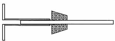
FIG. 18 A cork borer can remove (or insert) a stopper from a glass tube
or rod.
There is a trick for removing a stopper from glass tubing or a rod that uses a cork borer (see FIG. 18). Select a borer size that is just greater than the size of your glass rod or tube. Then prelubricate the outside of the borer with glycerin (preferred), or soap and water, and ease the borer between the stopper and glass.
When the borer is inserted all the way into the stopper, the glass tube or rod can be easily pulled out from the borer's hole. This trick can also be used to insert a tube or rod into a stopper by reversing the process.
3.6 Film Enclosures
Ground joint stoppers and snap-on plastic caps are commonplace, but many laboratory containers do not come with built in stoppers or seals. In the absence of a formal closure, or closures such as corks or rubber stoppers, there is the covering film, PARAFILM "M"®. ['PARAFILM "M"® is a product of American National Can, Greenwich, CT 06836.] PARAFILM "M"® is a thermoplastic film. Depending on its width, it can come in rolls of 50 to 250 feet in length. A portion of the plastic sheet is cut off the roll, laid over the clean dry top of a container, and stretched over and downward. The paper support film usually tears off during this process. The film forms a closure that can prevent spillage from the container during normal use.
PARAFILM is best used over water solutions, but may be used for short periods over polar-hydrocarbon solutions. Other organic solutions will dissolve the film. It is not designed to prevent spills from tipped-over containers, nor can it contain pressure. If you need to shake a container, do not depend on PARAFILM to maintain its seal. When agitating a container, leave a thumb, finger, or even the palm of your hand (depending on the size of the opening) over the seal to ensure against leakage.
PARAFILM is excellent for keeping air and dust out of containers, and it can be used to maintain containers clean when stored. Although PARAFILM does not wet (liquids run right off it), once used, it should be discarded to avoid contaminating other work. If it has been in contact with toxic materials, it should be thrown into a proper hazardous waste receptacle.
4. O-Rings
4.1 O-Rings in the Laboratory
O-rings are commonly found on mechanical vacuum pumps, rotary valves, and O ring joints. O-rings are used to separate environments. If an O-ring is attacked by the chemicals from one or both of these separated environments and fails, it will lose its protective sealing capabilities. Similarly, if an O-ring is left in a chemically destructive environment, it may become dysfunctional without ever having been used.
4.2 Chemical Resistance of O-Ring Material
When an O-ring needs replacement (such as in a mechanical vacuum pump), the manufacturer can provide, or recommend, an O-ring that will be resistant to the pump's vacuum fluid. On the other hand, when an O-ring is being used in varying conditions, you will be responsible for the selection of the proper O-ring material to maintain the integrity of your system and the health and safety of the operators.
As is typical for most polymers, the material composition of an O-ring may be suitable for one chemical environment and unsuitable for another. For example, ethylene propylene rubber is excellent in water conditions and exhibits essentially no swelling in these environments. However, if any lubrication is required, a petroleum-based lubricant will deteriorate the rubber. If needed, a silicone, glyc erin, or ethylene glycol lubricant is recommended.
An increase in size is a common reaction to O-ring materials in specific harsh environments. This is not necessarily bad if expansion enhances sealing. The worst that happens is that when the apparatus is taken apart, the O-ring is no longer able to fit where it came from and a new one must be used. Typically, how ever, the distorted O-ring tends to expand beyond its confines causing leaks and creating a mess.
There are seven primary materials from which O-rings are made. Table 9 catalogs these different materials, listing suitable and unsuitable chemical contacts and properties for each. Also included is a single O-ring price comparison (these 1991 prices are not meant to be absolute and are only offered to provide comparison).
By its design, an O-ring should not require stopcock grease to improve its seal, although the grease may provide peripheral assistance. For example, stopcock grease may be used on rotary valves to facilitate the axial movement of O-rings against the glass barrel. In addition, it may also be used as an extra protective barrier against solvents. For example, if you are using Viton O-rings in a ketone environment (i.e., acetone), you could lay a thin film of silicone grease on the O-ring to protect the surface. The easiest way to apply a thin film of grease is to rub a bit of grease on your fingertips, then rub it onto the O-ring. This method will limit the contact between the O-ring and the ketone, which in turn will increase the longevity of the O-ring. Do not, however, depend on this technique as a standard, or long-term, O-ring protection procedure.
[Be sure your hands are clean, to minimize contamination as much as possible.]
Incidentally, several companies cover one type of O-ring material (i.e., Buna-N) with a Teflon sheath. These O-rings have the resiliency of less expensive O-rings with the chemical inertness of Teflon.
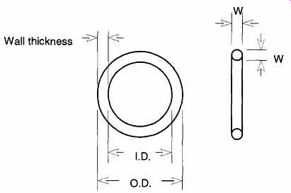
FIG. 19 The O-ring dimensions.
4.3 O-Ring Sizes
There are almost 400 standard-size O-rings. This number does not take into consideration military sizes, special orders, and unique shapes. Most standard-size O- rings are for use in reciprocating seals, static seals, and rotary seals, each of which makes contact on the inside or outside diameter of the O-ring.
O-ring dimensions are based on the ring's internal diameter (I.D.) and its wall thickness (W) (see FIG. 19), which are typically measured in English measurements (in thousandths of an inch). However, O-rings are not ordered by outside diameter or wall thickness. Rather, you order by a standardized size code called a dash number. O-ring sizes are grouped into common thicknesses, and the first number of the dash number represents a wall thickness group. All O-rings with the same first number have common wall thicknesses. Table 10 shows the dash number and sizes of metric dimensions of four commonly used O-ring thick nesses.

Table 9 Comparison of Primary O-ring Material
Occasionally, the outside diameter (O.D.) is also referred to, but such references are redundant.

Table 10 Representative Dash Numbers and Dimensions of O-Rings in Metric
Sizes
References
1. ASTM Designation C 162-85a, "Standard Definitions of Terms Relating to Glass and Glass Products," Annual Book of ASTM Standards, Vol. 15.02.
2. F.M. Ernsberger, Glass: Science and Technology, Vol. V, eds., D.R. Uhlmann and N.J. Dreidle, Academic Press, New York., 1980, Chapter 1.
3. G.W. McLellan and E.B. Shand, Glass Engineering Handbook, 3rd ed., McGraw Hill, New York., 1984, pp. 2-20.
4. R.C. Plumb, "Antique Windowpanes and the Flow of Supercooled Liquids," Journal of Chemical Education, 66, pp. 994-996 (1989).
5. "Practical Hints on Processing Duran®," prepared by Schott Glass.
6. G.W. McLellan and E.B. Shand, Glass Engineering Handbook, 3rd ed. McGraw Hill, New York, 1984, pp. 1-7
7. D.C. Holloway, The Physical Properties of Glass, Wykeham Publications LTD, London, 1973, p. 205.
8. J.E. Stanworth, Physical Properties of Glass, Oxford University Press, London, 1953, p. 209.
9. W.A. Weyl, "Chemical Composition and Constitution of Glasses," Proceedings of the Seventh Symposium of the American Scientific Glassblowers Society, pp. 16 23 (1962).
10. Ibid, Ref. 6, pp. 1-7.
11. C.S. Green, "The Art and Science of Glass Making," Proceedings of the Seventh Symposium of the American Scientific Glassblowers Society, pp. 7-15 (1962).
12. A.A. Smith, "Consumption of Base by Glassware," Journal of Chemical Education, 63, pp. 85-86(1986).
13. M.J. Souza, "Super Thin Windows for High Density 3 He Target Cells," Fusion, 42, pp 20-28 (1995).
14. V.O. Altemose, "Gas Permeation Through Glass," Proceedings of the Seventh Symposium of the American Scientific Glassblowers Society, pp. 61-70 (1962).
15. W.H. Kohl, Handbook of Materials and Techniques for Vacuum Devices, American Institute of Physics, Van Nostrand Reinhold, Woodbury, NY, 1967, p. 11.
16. G. Hetherington, K.H. Jack, and M.W. Ramsay, "The High Temperature Electrolysis of Vitreous Silica, Part I. Oxidation, Ultraviolet Induced Fluorescence, and Irradiation Colour," Physics and Chemistry of Glasses, 6, pp. 6-15 (1965).
17. R. Bruckner, "Properties and Structure of Vitreous Silica. I," Journal of Non-Crystal line Solids, 5, pp. 123-175 (1970).
18. R. Bruckner, "Properties and Structure of Vitreous Silica. I," Journal of Non-Crystal line Solids, 5, pp. 177-216 (1971).
19. Don Kempf, personal conversation, 1989.
20. W.H. Brown, "A Simple Method of Distinguishing Borosilicate and Soda Lime Glass," Journal of Chemical Education, 56, p. 692 (1979).
21. Kimble Glass Technical Data, Owens-Illinois Inc., Toledo, Ohio 43666, p. G-3, (1960).
22. Ibid, Ref. 6, p. 64.
23. T.C. Baker and F.W. Preston, "The Effect of Water on the Strength of Glass," Journal of Applied Physics, 17, pp. 179-188 (1946).
24. V.K. Moorthy and F.V. Tooley, "Effect of Certain Organic Liquids on Strength of Glass," Journal of the American Ceramic Society, 39, pp. 215-217 (1956).
25. T.A. Michalske and S.W. Freidman, "A Molecular Mechanism for Stress Corrosion in Vitreous Silica,: Journal of the American Ceramic Society, 66, pp. 284-288 (1983).
26. T. A. Michalske and B.C. Bunker, "Slow Fracture Model Based on Strained Silicate Structure," Journal of Applied Physics, 56, pp. 2686-2693, (1984).
27. E.B. Shand, Glass Engineering Handbook, 2nd Ed. McGraw-Hill Book Co., Inc., New York, 1958, p. 141.
28. Ibid Ref. 27, p. 143.
29. J. Walker, "What Causes the Color in Plastic Objects Stressed Between Polarizing Filters?," Scientific American., 246, pp. 146-52 (1983).
30. I.C.P. Smith, "Safety Letter; ref: Insertion or Removal of Glass Tubes in Rubber Bungs by Use of Cork Borers," Journal of the B.S.S.G., 12, p. 62 (1975).