AMAZON multi-meters discounts AMAZON oscilloscope discounts
<< cont. from part 3
4.11 The Top-Loading Balance
The advent of the servomotor brought new levels of accuracy to the top-loading balance. The servomotor gave top-loading balances the ability to weigh very small amounts quickly. Top-loading balances can generally measure as little as one-hundredth of a gram; more sensitive (and therefore more expensive) models can mea sure one-ten thousandth of a gram.
The operation of the servomotor is completely different from balance- beam balances because it does not require the use of counterbalancing weights. By their simplicity, servomotors have done to weighing what quartz crystals have done to timekeeping. This revolutionary device has allowed the removal of sluggish counterbalance weights and replaced them with electronics. Basically, the servomotor works by transferring linear motion to an electromagnetic force. The pan is established in a null position with an electronic light sensor. Any weight placed on the pan deflects the light sensor off its established position, and an electromagnetic current is initiated to return the pan to its original position. Because a greater weight requires a greater electric current to accomplish this task, the current can be directly read as a weight.
Because the neutral (or null) position can easily be established with a weight on the pan, recalibration and taring to the null position (before actual weighing) are accomplished by pressing a button.
Servomotors may be found in both single-pan balances and in top-loading balances. The operation of top-loading balances typically requires turning on the balance, pressing the null, or taring, button, and placing an object on the balance. The weight is calibrated and displayed on a screen within moments. Because the entire operation is electronic, the information can be sent to a printer for a permanent record, or to a computer for automatic processing. Computational capabilities (by software) can also be included to process such things as counting or statistical information about objects being weighed.
[Taring is the act of setting the scale to zero when a container is on the balance. Consequently, further weighings do not require subtracting the already-weighed container.]
Lest you think that the laboratory balance has been made perfect by the servo motor, realize that the servomotor is electronic and therefore is susceptible to various types of interference. Sources of interference include:
1. Weighing magnetic materials or placing the balance on a magnetic or ferrous table or surface. Magnetic objects cannot be weighed on a servomotor. To verify whether the magnetic or ferrous surface is affecting the readings, you can place the balance at various locations around the table and note any differences. In most circumstances, you do not need to bother trying to weigh with a servomotor on such a surface.
2. Electromagnetic interference. This interference can come from any electromagnetic-emitting field or source such as a CRT (from computer screens), RF generator, and radio transmitter. Using a hand-held radio transmitter, one can test the effects of electromagnetic interference on a balance. Erratic behavior of the balance's display may also be caused by interference on a floor above or below the balance location.
3. Dust contamination. Although it is easy to associate problems with dust on mechanical balances, it is less apparent why dust would affect an electronic apparatus. The answer is that because there is movement within the servomotor itself, dust collections between the magnet and electric coils is likely to cause erratic measurements. Additionally, if dust-sized ferrous particles find their way to the electromagnet, the servomotor could be shorted and rendered useless.
Analytical top-loading balances (those that can measure one-thousandth of a gram or smaller) have covers or doors to isolate the balances from drafts. These covers also provide limited protection from accidental spills. Typically, general use, top-loading balances do not have covers and are therefore subject to damage from accidents. Plexiglass covers may be obtained for many models of top-loading balances to protect them against such problems. Even a cardboard box placed over a balance will help reduce dust and limit accidental spills on the balance.
One problem inherent in top-loading balances is that the weight of objects to be weighed can vary when placed at different locations on the weighing pan.* Although this inconsistency should not apply, the problem is often complex and has to do with the geometry of how a top-loading balance is made and where the weight is distributed. Fortunately, testing for this problem is easy: Make several weighings of the same object at various locations on the balance pan. You may want to pre-mark the pan with some numbered geometric pattern (such as a star) to readily identify the location of any weight changes.
[Hanging pan balances, by their design, cannot have this problem.]
4.12 Balance Verification
If you have determined that your balance is making inaccurate measurements and you have eliminated human error, you not only cannot trust any future weighings, you must question all past weighings to the point of the last balance verification.
By maintaining written records of balance accuracy tests on a routine basis, the reliability of past measurements can be verified. Otherwise, every weighing made between the last verification and the first appearance of faulty readings is in doubt. If you find errors during equipment testing, you need to track their source and correct the problem. Otherwise, all future data will also be in doubt.
The tolerance of a given balance is based on the level of accuracy that the balance is designed to provide. The greater the tolerance, the less the precision. The less the tolerance, the greater the precision. The tolerance of a balance is a percentage of its last significant figure (in fact, tolerance is often defined by the last significant figure). If you have a balance which is accurate to ± 0.1 gram, you should not report a reading of 0.02 grams.
When we discuss a balance's quality, we generally are referring to its reliability and accuracy. A balance, no matter how sensitive, is not a quality balance unless it is reliable and accurate in its measurements. Because the accuracy of a balance can decrease from wear, dirt, or contamination, routine periodic verification is required. The manufacturer can provide suggested verification schedules that may have to be increased or decreased depending on the conditions in your lab.
All balances should be checked for:
1. Precision. Does the balance read the same weight over a series of measurements for the same object?
2. Accuracy and linearity. Does the balance read the same weight as that given for a calibration's nominal weight, and does the balance pro vide the same accurate weighings over the full weight range of the balance?
3. Readability. Is there accurate, repeatable deflection at the smallest unit of measurement that the balance is supposed to read, including any vernier or micrometer calibration (if present)?
4. Settling time. Does the balance take the same amount of time to settle at the final weighing as it did to null?
5. Response to temperature. Does the balance provide the same reading at 20°C as it does at 25°C?
6. Responses to other environmental disturbances. What are the effects on the balance of drafts, vibrations, electromagnetic fields, magnetic fields, and other conditions? Tests 4, 5, and 6 help identify under what conditions you should not bother making weighings. They should be reevaluated each time balance verification is made, because general wear and tear may exacerbate any environmental influence.
[If the amount of inaccuracy is less than your experimental limits, there is no reason to throw out any measurement.]
All electronic balances should also be checked for:
7. Warm-up variations. Some balances may indicate different weight values for the same object depending on how long the balance has remained in operation. See if any of the six previous tests is affected if the balance has just been turned on, left on for one-half hour, or left on for several hours.
Finally, top-loading balances should also be checked for:
8. Off-center errors. Does the balance make consistent weight measurements when an object is placed at different locations on the balance pan?
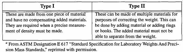
Table 25 Laboratory Weight Types

Table 26 Laboratory Weight Grades

Table 27 Tolerance by Class of Weights

Table 28 Tolerance by Class of Weights
4.13 Calibration Weights
Calibration weights should only be used to calibrate or verify the accuracy of a balance. Calibration weights should never be used to make weight determinations.
They should never be handled directly with hands, and they should be stored in safe locations away from environmental dangers.
A balance should be verified using the same calibrated weight each time.
Because calibrated weights have expected variations in tolerance, using different weights may yield varying test results and could lead you to believe your balance requires constant (minor) recalibration when, in fact, no such calibration is required.
The ASTM has categorized laboratory weights into the following divisions:
1. Types (I and II). Type refers to how the weights were constructed. Type I is of better quality than Type II. See Table 25.
2. Grades (S, O, P, and Q). Grade refers to how the surfaces of the weights are finished. S is better in quality than O and, likewise in turn, P and Q. See Table 26.
3. Classes (1,1.1, 2, 3, 4, 5, 6). Class refers to the amount of weight tolerance. The lower the Class number, the smaller the tolerance. Class 1.1 is a specialized class for calibrating low-capacity, high-sensitivity balances. See Table 27 & Table 28.
5. Temperature
5.1 The Nature of Temperature Measurement
Most of the measurements discussed in this section deal with physical properties, such as length, volume, or weight. Measurement of these properties can be made directly. Temperature is different because it is an energy property, and energy can not be measured directly. However, we can quantify the effect that one body's energy (in this case heat) has on the physical properties of another body, and we can measure that physical effect.
Unfortunately, heat energy does not have the same percentage of effect on all materials in the same way. For example, heat makes most materials expand, but few materials, if any, expand the same amount for an equal amount of heat. Thus, the size increase for one material (for a given amount of heat change) is unlikely to equal the size increase for another material (with the same amount of heat change).
On the other hand, it is possible to obtain the same temperature from two different materials if they are calibrated the same. This operation is done as follows:
take two different materials and heat them to a specific (and repeatable) tempera ture. Place a mark on some reference material that has not expanded (or contracted). Then heat the materials to another specific and repeatable temperature and place a new mark as before. Now, if equal divisions are made between those two points, the specific temperature readings along the calibrated region should be the same even if the actual changes in lengths of the materials are different.
An interesting aspect about temperature measurement is that calibration is consistent across different types of physical phenomena. Thus, once you have calibrated two or more established points for specific temperatures, the various physical phenomena of expansion, resistance, emf, and other variable physical properties of temperature will give the same temperature reading.
[Although not all of these temperature measurement techniques provide a uniform linear measurement, the variations are known and can be calibrated and accounted for.]
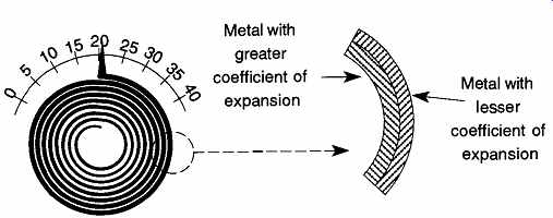
Table 29 The International Practical Temperature Scale of 1968 for K and
°C.

Table 30 Secondary Reference Points of the IPTS-68 in °Ca.
The establishing, or fixing, of points for temperature scales is done so that any one, anywhere can replicate a specific temperature to create or verify a thermometer. The specific temperature points become (in effect) the International Prototypes for heat. The General Conference of Weights and Measures accepted the new International Practical Temperature Scale of 1968 (IPTS 1968) with 13 fixed points (see Table 29). The new (IPTS 1968) scale was a revision from the IPTS 1948 (which had been amended in 1960).
There are two reasons for having many points with which to fix a temperature scale. One is that, as mentioned before, few materials affected by heat change length equally or linearly. Having many points allows scales to be calibrated in short ranges, where nonlinearity is less likely to have a pronounced effect. The second is that few, if any, thermometers can read all temperatures. Most thermometers are calibrated to read a small range of temperatures. Many "fixing" points allows for a robust system of calibration. Unfortunately, most of these points require expensive equipment, and even then they are not easy to obtain and/or verify.
However, in addition to these primary reference points, a secondary series of reference points was established by the IPTS-68 (see Table 30). These secondary points can more easily be used (than the primary temperature points) for testing temperature equipment such as liquid-in-glass thermometers. They are useful because they require less equipment and are therefore easier to obtain. Remember that these points are secondary standards and should not be considered primary standards.
Note that Table 29 refers to the temperature "K" or the temperature "°C." Both of these measurement scales are temperature measurement units. There is another scale, also known as "K," which is the unit of measurement for the Kelvin thermodynamic scale. Because heat is a thermodynamic property, temperature measurements should be capable of easy referral to the Kelvin temperature "K," more properly known as the Thermodynamic Kelvin Temperature Scale (TKTS).
One degree K is exactly equal to the thermodynamic unit of K, and likewise is exactly equal to one degree C. Otherwise, any specific temperature in one scale can easily be converted to another by the relation K = °C + 273.15 Values given in Kelvin temperature (TKTS) are designated as "T." Values given in degrees centigrade (°C) are designated as "t." When either T or t is used to express temperature from the International Practical Temperature Scale, it should be designated as T68 or t68* For example, if you were to refer to the freezing point of mercury, you would write -38.862%g.
5.2 The Physics of Temperature-Taking
When we measure the temperature of a body, we are depending on the heat of the body to be transferred to (or from) our measuring device. Once the heat has been taken to (or from) our measuring device, any physical changes in that device are interpreted as a temperature change. The process where we analyze the effects caused by a property to determine the amount of that property is known as inferred measurement. For temperature we have a variety of physical properties from which to infer the amount of energy (heat) that a given object has.
Measurement of temperature (or any energy property) has one major difference from measurement of physical materials: It is not cumulative. To measure the length of a room, you can lay several meter sticks end to end. The sum of the number of meter sticks will be the length of the room. Temperature, however, is not cumulative. If you have a liquid that is hotter than the range of temperatures measurable on one thermometer, you cannot use a second thermometer to obtain the remaining temperature.

Table 31 Ranges of Common Temperature Measuring Devices
Because the temperature ranges and conditions of a system can vary, a variety of materials have been incorporated into different types of thermometers. The following is a list of common thermometer types and the property measured in each to obtain a heat measurement.
1. Liquid-in-glass thermometer. Volume of liquid increases as heat increases.
2. Gas or vapor at constant volume. Pressure of gas increases as heat increases.
3. Dilatometer (or bimetal coil). As heat rises, the length of one metal expands more than the length of the other metal.
[ The subscripted "68" is used to indicate that these temperatures conform to the IPTS-68 guidelines. ]
4. Platinum wire. Electrical resistance of the wire increases as heat increases.
5. Thermocouple. Thermal emf goes up as heat increases.
Table 31 displays some common temperature ranges of a variety of thermometers.
In addition to desired temperature ranges, variables affecting the selection of a thermometer may include:
1. The material to be studied. Is it acidic, alkaline, oxidizing, flame, plasma, hydrocarbon solvent, or conducting? One environment may affect one type of thermometer, but have no effect on a different type of thermometer.
2. The amount of material to be studied. The smaller the sample, the more you need to be concerned about the heat capacity of the thermometer.
More specifically, a large thermometer with a large heat capacity can change the temperature of a small sample, whereas a small thermometer with a small heat capacity will read the temperature of a small sample without changing the temperature.
3. The environment. Is is cramped, dusty, wet, hot, cold? Some thermometers require very controlled environmental conditions to properly operate.
4. The cost. Platinum resistance thermometers are incredibly accurate over a wide temperature range. Unless you need the accuracy they can pro vide, you might be wasting your money.
5. The amount of support equipment required. A thermocouple is not very expensive, but the controller can be. Similarly, constant volume gas thermometers can be very bulky and cumbersome.
The reason for the variety of thermometers is that no one type is economical, practical, accurate, or capable of measuring all temperatures in all conditions.
Selecting the right thermometer is a matter of analyzing your needs for a given job and identifying what thermometer best satisfies those needs.
As stated before, temperature (or heat) is a form of energy. Heat always travels from hot to colder bodies until thermal equilibrium is achieved. Thus, ice in a drink does not cool the drink. Rather, the heat in the drink is transferred to the cold ice, causing the ice to warm and melt. What remains is a "colder" drink because heat energy was lost melting the ice.
The significance of this "ice story" leads us to an important principle of temperature measurement: The act of taking an object's temperature changes the object's temperature because we depend on some amount of heat being given off or absorbed by the object to affect our measuring device. If the object being studied is very large in comparison to the temperature measuring device, this effect is negligible. If the material being studied is in a dynamic system (with heat constantly being introduced), the effect is irrelevant. However, if a small, static amount of material is being studied, the thermometer may have a significant effect. You need to select a temperature recording device that will have the least amount of effect on the sample's temperature. Optimally, you want the heat capacity of the temperature measuring device to be so much smaller than the heat capacity of the material being studied that it provides an insignificant change.
Temperature (heat) is transferred from one body (or region) to another by three thermal processes, conduction, convection, and radiation-adsorption, or some combination of the three.
1. Conduction is the transfer of heat from one body to another by molecules (or atoms) in direct contact with other molecules (or atoms). This mechanism explains how a coffee cup is heated by hot coffee.
2. Convection is the physical motion of material. Examples of this process would include hot air (or water) rising and cold air (or water) sinking.
Rigid materials cannot have convection.
3. Radiation and absorption are the results of heat energy being transformed into radiant energy (the energy, for example, that gives us a suntan).
One excellent example of an energy-efficient vessel is the Dewar. The Dewar effectively limits heat transfer by limiting all three heat transport mechanisms.
Because its glass is a poor conductor of heat, the liquids on the inside of the Dewar do not readily conduct their heat to the outside surfaces. The vacuum in the space between the two glass layers prevents heat transfer by both conduction and convection. Finally, the walls of the Dewar are silvered to prevent loss of heat by radiation and absorption.
5.3 Expansion-Based Thermometers
Because most materials expand as heat increases, the measurement of such expansion is used as a basis of heat measurement. Because the expansion of most materials is reasonably constant across a given range of temperatures, the amount of expansion can be quantified by a coefficient of expansion formula.
A linear coefficient of expansion is based on the following formula:
(eqn. 3)
LAt where a = linear expansion
Lt = final length
LQ = original length
At = change in temperature
A volumetric coefficient of expansion is based on the following formula:
(eqn. 4)
where p = volume expansion
Vt = final volume
VQ = original volume
At = change in temperature
A pressure coefficient of expansion is based on the following formula:
(eqn. 5)
where (3 V = volume expansion Pt = final volume Pg = original volume At = change in temperature
FIG. 29 Bimetal thermometers use two metals of different expansion to
create spiral thermometers.
As can be seen, all coefficients of expansion are based on the amount of size change divided by the product of the original size and the change of temperature that occurred. The result of this type of equation can be calculated for any material. Because a coefficient of expansion is not necessarily consistent across a range of temperatures, coefficient of expansion tables (or listings) will be an average across a given temperature range. For example, to state that the coefficient of expansion of glass is 0.000003 3 means nothing unless you specify that you are talking about laboratory borosilicate glass in the temperature range of 0 to 300°C.
It is critical to be precise about the composition and/or nature of the material being analyzed. By changing the composition of any material, even a small amount, the coefficient of expansion can be altered significantly.
5.4 Linear Expansion Thermometers
Linear expansion is most commonly used in bimetal spiral thermometers, which use two metals with different coefficients of expansion (see FIG. 29). The two metals can be welded, soldered, or even riveted together. As the metals are heated, the metal with the greater expansion will cause the spiral to flex open or close depending on which side the metal with the greater coefficient of expansion is on.
A reverse in temperature will cause a commensurate reversal in the flexing.
Spiral thermometers are easily recognized as part of most room thermostats.
They also are used in meat and oven thermometers.
5.5 Volumetric Expansion Thermometers
When you mention thermometers, volumetric expansion thermometers are what typically come to mind (see FIG. 30). The material that expands within a volumetric expansion thermometer is typically mercury or (ethyl) alcohol. Another name for a volumetric expansion thermometer is a liquid-in-glass thermometer.
The parts of a standard liquid-in-glass laboratory thermometer are as follows:
[Not all liquid-in-glass thermometers have all these parts.]
1. The bulb. The storage area for the liquid. The size of the bulb is based on the size of the thermometer.
2. The stem. The main shaft of the thermometer.
3. The capillary. The channel that carries the liquid up the stem. The narrower the capillary, the greater the accuracy that can be achieved.
However, at a certain point, temperature readings are affected by surface tension of the liquid and the glass of the thermometer, so manufacturers are limited as to how accurate a liquid-in-glass thermometer can be.
4. The main scale. This scale is where the temperature is read. Some thermometers are designed to read a specific temperature range for a specific test. A doctor's thermometer is one example of this type of scale.
5. The immersion line. Sets the placement depth for partial-immersion thermometers.
6. The expansion chamber. An expanded region at the top of the capillary designed to prevent a buildup of excessive pressure from the expanding liquid.
7. The contraction chamber. Used to reduce the necessary length of a thermometer when the desired temperature range would otherwise require a very long thermometer.
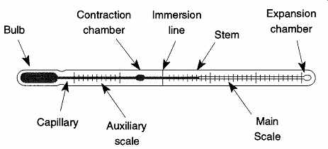
FIG. 30 The principle features of the solid-stem liquid-in-glass thermometer.
From Figure 3 from the NBS Monograph 90, "Calibration of Liquid-in-Glass Thermometers," by James F. Swindells, reprinted courtesy of the National Institute of Standards and Technology, Technology Administration, U.S. Department of Commerce. Not copyrightable in the United States.
8. The auxiliary scale. Required on thermometers whose calibrated region does not include an IPTS (International Practical Temperature Scale) calibration point. For example, say you have a thermometer with the range of 20° to 80°C. The auxiliary scale would include the range of -5° to 5°C so that the thermometer could be verified against the triple point of water.
Along the shaft of the thermometer, above the liquid in the thermometer capillary, is an air space typically filled with nitrogen. The nitrogen is under pressure to prevent condensation of the liquid in the upper portions of the thermometer. The pressure of the gas in the confined space will vary according to changes in temperature. Therefore, exposing the air space of a thermometer to unusually hot or cold temperatures can affect readings.
Within the bulb is a large repository of the expansion liquid. However, be aware that you cannot obtain an accurate temperature reading by placing just the thermometer bulb in the test material. When only the thermometer's bulb is under the heat's influence, the amount of expansion (or contraction) of the liquid beyond the bulb region is unknown. Any liquid not immersed in the sample being measured is not under the same influence as the liquid that is immersed. For example, if the bulb were placed in a boiling solution while the stem was in an arctic frost, the liquid in the stem would be contracted more than it would be if the stem was in a warm room.
It is possible to compensate on the calibration lines for these limitations to a certain degree. To make this compensation, three different types of liquid-in-glass thermometers have been designed with three different immersion requirements.
They are:
1. Total-immersion thermometers. Thermometers that require the liquid in the stem to be completely immersed in the measured liquid. The placement of the thermometer must be adjusted during use so that the liquid in the bulb and stem are always immersed in the sample. These thermometers are the most accurate.
2. Complete-immersion thermometers. Thermometers that require the entire thermometer to be immersed in the measured liquid.
3. Partial-immersion thermometers. Thermometers that require only the bulb and a specified portion of the stem to be immersed in the measured liquid. There will be a mark or a line on the thermometer stem designating how far into the material the thermometer must be placed. The standard partial-immersion thermometer has a line 76 mm (3 inches) from the end of the bulb.
There are many specialized thermometers available. Some are used to obtain maximum and minimum temperatures, while others are used for specific tests.
The ASTM has defined a series of special partial-immersion thermometers for specific tests. These thermometers are identified as ASTM thermometers and are marked with a number followed by a "C" (for centigrade) or an "F" (for Fahrenheit). The number is strictly an identifying number with no relation to the temperature range the thermometer can read. Because these thermometers are specialized, they have immersion lines at unique locations on their stems.
Some thermometers have standard taper joints or ridges on the body of the glass to fit specific equipment such as distillation or melting point apparatus. These thermometers provide two types of position control. They set the bulb at just the right height within specialized equipment and ensure that the liquid column is sufficiently immersed in the heated sample. However, most thermometers do not have built-in controls and the user must not only select the right thermometer, but also adjust the thermometer to its proper level within the equipment.
The use of complete-immersion thermometers is fairly obvious. However, it is not always possible or practical to completely immerse a thermometer. For example, if the solution is not transparent, it is not possible to see the temperature.
There are tables that provide correction values for readings made when total immersion thermometers are not sufficiently immersed. In the absence of such tables, use the formula for calculating stem correction given in the following equation.
Stem correction = Kn(tb - ta) (eqn. 6)
where K = the differential expansion of the liquid
n = number of units (in degrees) beyond the immersed stem section
tb = is the temperature of the bath
ts = is the temperature of the liquid column (a second thermometer is required for this reading)
Some general values for K are K = 0.00016 for centigrade mercurial thermometers and K = 0.001 for centigrade organic liquid thermometers
To better understand stem corrections, consider the following example:
Thermometer reading: 105°C
Temperature of thermometer stem: 37°C
Number of units (in degrees) of stem beyond immersed liquid: 43
Stem correction = 0.00016 x 43(105°C - 37°C)
Stem correction = 0.47°C Final thermometer reading: 105.47 °C
[Although the specific value of K varies as the mean temperature of the thermometer liquid varies, these values are sufficient for most work.]
Although this stem correction is relatively small, stem corrections of 10 to 20 degrees are not out of the question. Stem correction may be unnecessary depending on the difference between the sample and room temperature, the temperature ranges you are working with, or your tolerance requirements. It is a good practice to see what the stem correction would be to see if it is significant or not before assuming that it is not necessary.
If you make stem corrections, be sure to indicate this fact in any work you publish. Likewise, when temperature measurements are cited in literature and no stem correction is mentioned, it is safe to assume that no stem correction was made.
Partial-immersion thermometers have a greater tolerance (and therefore less precision) than total immersion thermometers. Interestingly enough, when a total immersion thermometer is only partially immersed and no stem correction is made, the accuracy is likely to be less than a partial-immersion thermometer.
The tolerance ranges for all thermometer designs are quite different from tolerance ranges for other calibrated laboratory equipment such as volumetric ware. Tolerance varies mostly with graduation ranges and secondly with whether the thermometer is of total- or partial-immersion design. Table 32 shows NIST tolerance and accuracy limitations. Remember that tolerance is a measure of error (±), or how different a measurement is from the real value. A large tolerance indicates less accuracy, whereas a small tolerance indicates greater accuracy. Accuracy is the agreement of the thermometer reading to the actual temperature after any correction is applied. Conditions that can affect a thermometer's accuracy include variations in capillary diameter and external pressure variations on the bulb.
5.6 Short- and Long-Term Temperature Variations
Thermometers do not maintain their accuracy over time. Depending on how they are used, they are subject to short-term or permanent changes in measurement.
The problem stems from the fact that the density of glass and the volume of the bulb change as temperature changes. If a thermometer is brought to a high temperature and allowed to cool very fast, its density may not return to the original density. Under these conditions the glass may "set" to a new density while cooling and may thereafter be too viscous to return to the originally manufactured density.
By selecting special types of glass, thermometer designs, and manufacturing techniques, manufacturers limit the amount of temperature-caused errors as much as possible.
[Because partial-immersion thermometers are designed for a specific test, uniformity of procedure is more important than overall accuracy.
There is likely to be changes in the stem volume as well, but the amount of those changes is likely to be negligible.]

Table 32 Tolerance (±) and Accuracy for Mercury Thermometers"
Generally, using a thermometer only within the scale range for which it was designed should limit changes. Overheating a thermometer (not designed to be used for high temperatures) above 260°C should be avoided. When change occurs, it typically results in a low reading that is often called an ice-point depression. During temperature-caused changes, the bulb increases in size as the temperature increases, but it does not contract to its original size as the temperature returns to normal. Thereafter, once recalibrated at the ice point, the thermometer temperature will always read less than the real temperature.
These changes may be either temporary or permanent, often depending on whether the thermometer was cooled slowly through the higher-temperature regions, or simply removed and haphazardly laid on a table. Depending on a thermometer's glass quality, the hysteresis* effect can cause from 0.01 to 0.001 "of a degree per 10 degrees difference between the temperature being measured and the higher temperature to which the thermometer has recently been exposed."
[Hysteresis is when a material is stretched or distorted to a new position or shape and does not return to its original position or shape.]
A thermometer will indicate short-term changes when used below 100°C, and it will recover an error of 0.01 to 0.02 degrees in several days. Admittedly, these are small amounts of error. Greater amounts of temporary error can be exhibited when a thermometer is used for relatively high temperature readings and then is immediately used for relatively low temperature readings. Thus, it may be advisable to separate thermometers not only by their temperature ranges, but also by the temperature ranges for which they are used. This practice is especially important if your work requires accurate thermometric readings.
Long-term changes are generally caused when a thermometer is maintained at high temperatures for extended periods of time (> several hundred hours).
Such conditions can cause errors as great as 12°C. It is also possible to cause permanent changes from repeated cycling at lower temperatures between -30°C and room temperature.
It is uncommon to observe an alteration due to a temperature-induced change in the readings along selective parts of the thermometer scale. Typically they are more of a dropping of the entire scale reading. Thus, periodically checking the zero point with an ice bath, or checking the water boiling point with a steam bath, can ensure the accuracy of your thermometer. It is not necessary to recalibrate the entire stem of the thermometer.
5.7 Thermometer Calibration
Steam bath calibration for the liquid-steam point of H2O is not easy for many labs to use because of its expense, and the equipment is difficult to use. In addition, the user needs to account for atmospheric pressure variations and the effects of local variations of gravity on the barometer. Fortunately, the ice-point calibration is easy to set up and use.
Any thermometer with 0.0°C on either its main or auxiliary scale can be calibrated with an ice-bath calibration apparatus that can be assembled with the following material:
1. A 1- to 1.5-liter Dewar flask, cleaned and rinsed with distilled water
2. Crushed ice made from distilled water
3. A (clean) siphon to remove excess melted ice Fill the Dewar approximately one-third full with distilled water. Place the end of the siphon tube to this level, and then fill the Dewar to the top with crushed ice.
The thermometer should be inserted so that the thermometer is immersed to the 0.0°C level (if calibrating a complete-immersion thermometer) or inserted to the immersion line (if calibrating a partial-immersion thermometer). The thermometer is likely to require support to maintain its proper position. Let the entire apparatus sit for 15 to 30 minutes, to reach equilibrium. Periodically add more ice, as needed, and remove any excess water with the siphon. If the ice is kept clean and tightly packed around the thermometer bulb and stem, it is possible to achieve accuracy to within 0.01°C.
If you are concerned about accurately calibrating the entire scale of a particular thermometer, it may be sent to the NIST for calibration for a fee. You will need to contact the NIST for more information on that service. Once calibrated, any variations in the zero point should not significantly alter the corrected calibrations along the scale.
NIST-calibrated thermometers are expensive, but very accurate tools. Unfortunately, they require special use and maintenance to maintain their integrity. Not only can abuse alter their calibration, but general use can as well. For example, if you are using an NIST-calibrated liquid-in-glass thermometer on a regular basis, an ice-point recalibration should be taken after each measurement. These variations should be added to the adjustments made to the corrected scale temperatures.