AMAZON multi-meters discounts AMAZON oscilloscope discounts
1. Joints and Connections
The ability to assemble and disassemble apparatus components has been a long standing requirement in laboratories. The use of ground joints for this purpose is not new, but standardizing the taper so that one piece from one lab can be attached to another section of apparatus in another lab has only been in common use since just after World War II. Currently, there are many standardized ways to join and separate laboratory glass apparatus.
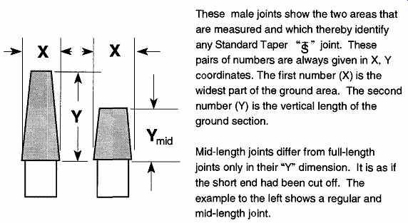
Fig. 1
Full- and mid-length standard taper joints. These male joints show the two
areas that are measured and which thereby identify any Standard Taper "s " joint.
These pairs of numbers are always given in X, Y coordinates. The first number
(X) is the widest part of the ground area. The second number (Y) is the vertical
length of the ground section. Mid-length joints differ from full-length joints
only in their "Y" dimension.
It is as if the short end had been cut off. The example to the left shows
a regular and mid-length joint.
1.1 Standard Taper Joints
Standard Taper Ground Joints. These joints have the same taper throughout the world. This taper, a 1:10 ratio, provides for the ground section to decrease in size one unit in width for every 10 units of length. These units are always in "mm" (see Fig. 1).
Standard taper joints are used in matching inner and outer (also called male and female) members. They are made in a variety of standardized sizes and shapes.
Figures 2 and 3 illustrate the shape variations available. In general, how a joint will be used determines which joint design should be selected.
Inner Joints. Common varieties of inner joints are shown in Fig. 2.
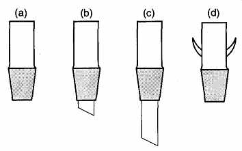
Fig. 2
Various types of inner joints.
Figure 2(a) is a standard full-length joint, the one most commonly seen in the lab. Figure 2(b) has a small "drip tip" extended from the small end of the joint.
This joint is commonly placed on condensers to prevent distillate from coming in contact with, and/or dissolving, stopcock grease. Figure 2(c) has an extended drip tip that a glassblower can bend to aim the liquid flow, or seal to other pieces of glass. The manufacturer adds these extensions during initial fabrication, before the joint is ground to the proper taper. If a glassblower were to try to seal such an extension onto a Type (a) joint, the distortion caused by the sealing action would alter the taper of the joint, necessitating regrinding. Manufacturers also provide joints that already have hooks for springs on them, as in (d).
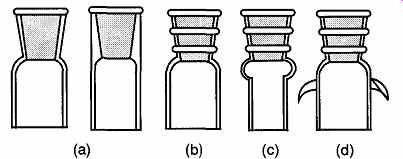
Fig. 3 Various types of outer joints.
Outer Joints. These joint also have a variety of forms (see Fig. 3). Both (a) examples have heavy walls and can receive a moderate amount of physical abuse.
Example (b) has thinner walls on the ground joint section. Ribs are placed around the joint for extra strength. Thin walls are important for experiments with large temperature fluctuations that, in turn, might cause glass expansion or contraction.
Changes in glass size could cause separation of the inner and outer joints, thus causing leaks. Example (c) is often referred to as an "old style" joint. It can easily be identified by the small bulb just below the ground section. This bulb provides a resting place for the joint on a two-finger clamp without requiring extra pressure (see Fig. 4). The squeezing of a column to maintain position (when there is no bulb to support the weight) is the exclusive cause of cracks on the sides of columns. If the joint is not held vertically, the bulb can also cause a minor hold-up of fluids. Example (d) shows outer joints with pre-attached hooks.
Standard taper joints are formed by a process called "tooling," which establishes the physical form from a simple glass tube. After the joint is made, it is ground using various grades of carborundum grinding compounds to achieve the proper tapered smooth finish. In addition to the standard ground surface joint, Wheaton Scientific Co. also makes a joint with a smooth polished glass surface. These joints are known as Clear-Seal joints. Instead of being ground, the joint is heated until soft and then suctioned over a mandrel. The suctioning causes the glass to collapse onto and conform to the mandrel shape.
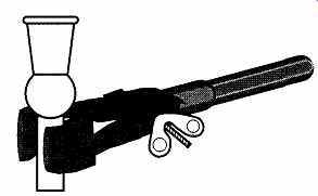
Fig. 4 Old style outer joint in a two-finger clamp.
The "old" style female joint is very good to use with two-finger clamps. It is not necessary to squeeze the wing nut tightly to securely hold the joint. Rather, the bulb of the joint rests easily on the clamp.
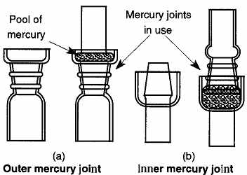
Fig. 5
Examples of mercury joint seals. (a) Outer mercury joint (b) Inner mercury
joint
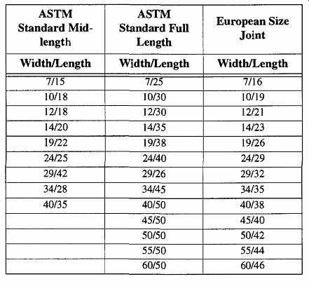
Table 1 Comparison of ASTM Mid- and Full-Length Joint Size to European
Joint Size
Wheaton Clear-Seal joints have the unique attribute that they do not need any stopcock grease. However, they require very special handling and storage, because any scratch can destroy their sealing abilities. Additionally, when joint members are joined, special care must be taken to ensure that no paniculate matter lodges between the pieces. Such matter can prevent a proper seal, scratch the sides of the members, and/or cause the members to jam or stick. Because no stop cock grease is used with Clear-Seal joints, it is more difficult to separate stuck members.
Clear-Seal joints are mandatory when using diazomethane (CH2N2) as a methylating reagent for carboxylic acids. Diazomethane is a toxic, irritating gas which has the tendency to self-detonate. This self-detonation can occur when the diazomethane is in either a gaseous or liquid state. It has been proven that rough surfaces (such as ground joint surfaces) can initiate such detonations. Thus, only Clear-Seal joints should be used in diazomethane chemistry.
Mercury Seal Joint. This joints is no longer used for its intended purpose because of improvements in joint manufacturing as well as safety concerns about mercury in the lab. The mercury seal joint (see Fig. 5) was originally used to provide leak-tight seals so that gases couldn't pass by ground joint seals. After the ground glass joints were in place, a small pool of mercury was poured in the trap to complete the seal.
The outer mercury joint is still commonly used by glassblowers who need to seal tubing onto the ground end of an outer joint (for example, on a water-cooled condenser where the joint also needs to be water cooled, as in Fig. 6). Without the extension of glass, a seal of this type would distort the walls of the joint, making it useless. This outer joint, therefore, provides the same advantage afforded by extended drip tip inner joints (Fig. 2(c)).
European Joint Sizes. In Europe a different set of joint lengths are used than what are common in North and South America. The European joints are just a bit longer than the ASTM standardized midlength joints found in North America. See Table 1 to see how these joints match up with standard and midlength joints.
Normally, laboratories in the America are not likely to encounter European joints. However, it is possible to encounter a Standard Taper Joint that is neither full nor midlength if one is doing joint research with European labs, or when obtaining laboratory apparatus from European companies.
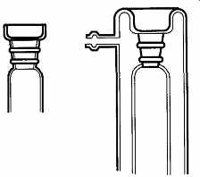
Fig. 6 Sample of a water-cooled condenser using a mercury seal joint.
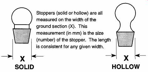
Fig. 7
Stopper plugs. Stoppers (solid or hollow) are all measured on the width of
the ground section (X). This measurement (in mm) is the size (number) of
the stopper. The length is consistent for any given width.
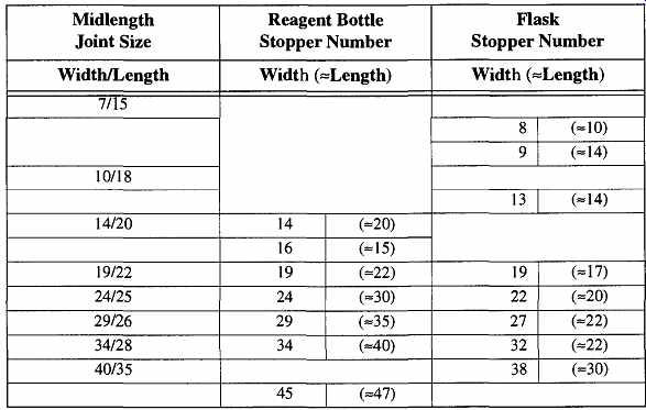
Table 2 Comparable Sizes of Standard Taper Joints and Stoppers
Because the taper ( 1:10) and the width are the same, it is easy to insert and use European joints in any ASTM Standard Taper Joint. However, the European joint will extend just beyond the midlength joint, and the full-length joint will extend just beyond the European joint. Because of this mismatch, there is a greater chance for stopcock grease to be exposed to materials within the containers. This can be resolved by either being more judicial when applying the stopcock grease (don't overdo it), using a Teflon sleeve, or changing one or the other joints to match.
The Stopper Plug. There are two types of ground stoppers: reagent bottle stoppers and flask stoppers. They have the same 1:10 taper as the joints previously mentioned, however, they are listed by only one number based on their width measurement (see Fig. 7). Both stopper types have a flattened disk above the ground section for easy holding. Because the term "pennyhead stoppers" can refer to either reagent or flask stoppers, a complete description of the stopper you want is important for complete identification.
Reagent bottle stoppers are essentially the same size as midlength joints, although their lengths are somewhat shorter. A size 14 stopper is the same size as a 14/20 joint, and it can fit into a 14/20 female joint (see Table 2). Do not expect a stopper plug to maintain a vacuum, however, unless the stopper is hollow. The thinner walls of a hollow stopper will adjust to temperature changes better than a solid plug, so there is less chance for the members to become separated due to the expansion or contraction of the glass. In addition, only hollow stoppers are ground to the standards required for vacuum components.
Flask stoppers come in widths (sizes) that are different from other joints and stoppers; therefore, flask stoppers are not interchangeable with joints or stoppers (see Table 2).
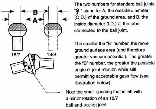
Fig. 8
Ball-and-socket joints.
The two numbers for standard ball joints "vp " stand for A, the outside diameter (O.D.) of the ground area, and B, the inside diameter (I.D.) of the tube connected to the ball joint.
The smaller the "B" number, the more ground surface area (and therefore greater vacuum potential). The greater the "B" number, the greater the possible angle of joint rotation while still permitting acceptable gass flow (see illustration below).
Note the small opening that is left with a minor rotation of an 18/7 ball-and-socket joint.
1.2 Ball-and-Socket Joints
Ball-and-socket joints are typically used when the union between apparatus pieces is not linear. Ball-and-socket joints have a different type of measurement system than standard taper joints (see Fig. 8). They cannot be used for significant (e.g., > 10^3 torr) vacuums, and they should not be relied upon for static vacuum environments.
Ball-and-socket joints must be held together with either a metal spring type of clamp (like a clothespin) or a semirigid plastic clamp. Because ball-and-socket joints cannot be used without one or the other type of clamp, be sure to include the right-size clamp when ordering apparatus that have ball-and-socket parts, if they are not otherwise supplied.
The clamp size required for ball-and-socket joints is identified from the outer diameter measurement. Thus, a size 18 clamp is used for either an 18/7 or an 18/9 size O-ring joint.
1.3 The O-Ring Joint
The O-ring joint (see Fig. 9) has no ground sections, and as opposed to other joint types, both members of an O-ring joint are identical. For sealing, O-ring joints require placing an O-ring, made from some polymer material (see Sec. 1.4), between the joint members, which are held together by the same type of "clothes pin" clamp used with ball-and-socket joints.
[The one-piece plastic clamp used with ball-and-socket joints will not work with O-ring joints. ]
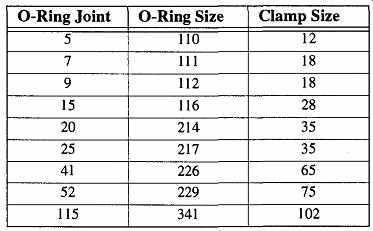
Table 3 O-ring and Clamp Sizes for O-ring Joints
Because clamp identification numbers are derived from their relationship with ball-and-socket joints, there is no relationship between which size clamp should be used with which O-ring joint. There is no one-to-one relationship with O-ring joints and ball-and-socket joints; one clamp size is likely to fit several different size O-rings joints. Table 3 provides the recommended O-ring and clamp sizes for respective O-ring joints. Like ball-and-socket joints, be sure to order the appropriate size clamp when ordering apparatus with O-ring connections.
O-ring joints can easily be used with vacuum systems (<10^7 torr) and are particularly useful for quick-release connection. Occasionally it is necessary to leave a thin film of stopcock grease on an O-ring's surface to either help the vacuum capabilities of the joint, or to protect the O-ring's surface from the effects of a solvent.
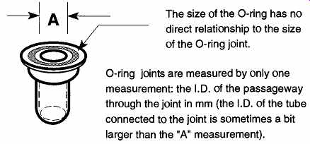
Fig. 9 The O-ring joint.
The size of the O-ring has no direct relationship to the size of the O-ring joint. O-ring joints are measured by only one measurement: the I.D. of the passageway through the joint in mm (the I.D. of the tube connected to the joint is sometimes a bit larger than the "A" measurement).
1.4 Hybrids and Alternative Joints
A hybrid O-ring/ball joint (see Fig. 10) is available. This joint has the vacuum capabilities of the O-ring joint along with the variable angle abilities of a ball-and socket joint. Typically, the socket side of an O-ring joint is ground and an O-ring cannot achieve as good a vacuum as it could against a non-ground surface.
Because of this, some manufacturers are supplying unground sockets for use with O-ring ball joints. Regardless of the type of socket used, because this design does not require stopcock grease, it can be used in conditions where a connection would otherwise be impossible. Unfortunately, there may be liquid holdup within such a joint.
There are occasions when a solvent must remain in contact with a connection for several days and the connection must maintain a vacuum. Depending on the nature of the solvent, standard grease and most O-rings cannot be used in these situations.
An alternate solution to complications with long-term solvent contact with CD-ring polymers is the Solv-Seal joints by Andrews Glass Co. Inc. These joints seal together with a double-ringed Teflon seal (see Fig. 11) within a specially designed glass joint. Although there is a Viton O-ring within the Teflon sealing unit, the O-ring is used as backup protection. The primary containment for the material within the system is the Teflon.
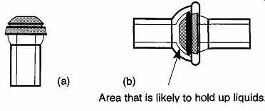
Fig. 10 The O-ring ball joint without the O-ring in place (a), and the
hold-up it can create (b).
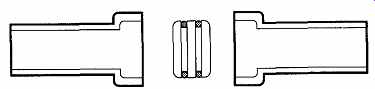
Fig. 11 Solv-Seal joints. The Solv-Seal joint, from the Lab Crest Product
line, is made by Andrews Glass Co. Inc, reproduced with permission.
1.5 Special Connectors
There are several special connectors that provide "demountable" connections between glass to glass, glass to metal, or metal to metal. These connectors provide many advantages over standard connections.
Swagelok® fittings (see Fig. 12) are used to connect metal tubes to metal tubes. These fittings, which provide permanent connections on metal tubing, are not meant for use on glass. These connectors have a pair of small metal ferrules (like a collar), one of these ferrules tightens around a metal tube as the Swagelok nut is tightened, while the other is a washer. The tightened ferrule is permanently attached to the metal tube and cannot be removed. It provides a leak-tight fit that can be used in high-vacuum or high-pressure conditions.
Swagelok fittings are made in a wide variety of styles, connections, and sizes.
They are especially useful when connecting copper tubing for delivering nitrogen gas to various systems around a lab, or when making connections for extension tubes on metal high vacuum systems.
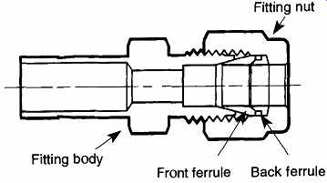
Fig. 12 The Swagelok fitting. The illustration of a Swagelok® Fitting
is used with permission of Swagelok Co., Solon, Ohio 44139. The illustration
was sup plied by the Swagelok Co.
Cajon® Ultra-Torr® fittings are similar to Swagelok fittings except they are reusable and can be used on metal as well as glass and plastic (see Fig. 13).
Instead of a metal ferrule, there is an O-ring that imparts a leak-tight seal. They are made in a wide variety of styles and sizes. Unlike Swagelok® fittings, Cajon Ultra-Torr fittings cannot be baked out for ultra high-vacuum work.
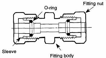
Fig. 13 The Cajon® Ultra-Torr® fitting. This illustration of a Cajon®
Ultra-Torr® Fitting is used with permission of Swagelok Co., Solon, Ohio
44139. The illustration was supplied by the Swagelok Co.
If you are going to connect a Cajon Ultra-Torr fitting to glass, first verify whether the fitting is metric or not. If the fitting is non-metric, use the appropriate type of tubing. Medium and heavy wall tubing are both made in English sizes, but are identified in metric numbers (see Table 9 and Table 10). Because glass tubing has variations in O.D. tolerance (see Sec. 4.2), pretest the fitting before you commit yourself to any construction. This pretesting can be done by simply ensuring that the Ultra-Torr® tightening nut can slip over the tube. Because glass has no macroscopic compressional abilities, do not force a Cajon fitting onto glass. If it does not fit, select another piece of glass that does fit.
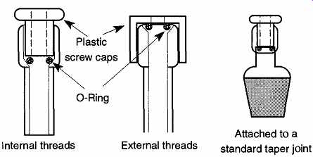
Fig. 14 Several generic designs of glass-threaded connections.
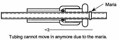
Fig. 15 Internal motion of the inserted tube is blocked by the addition
of a maria.
There is a glass variation of the Cajon fitting design available from several glass industry sources. These variations go under a variety of names (depending on the manufacturer), but are typically under the classification of glass-threaded connections (see Fig. 14). There are adapters made with a threaded connection on one end and either (a) a glass tube ready to be attached to some glass apparatus or (b) a standard tapered joint on the other, made out of glass or Teflon. These connectors can be used (for example) to support thermometers within a flask.
Glass-threaded connectors can be used for limited vacuum operations. How ever, there often is nothing to stop the inserted tube from being sucked in unless there is some step in the fitting or ridge on the tube. Cajon Ultra-Torr fittings typically have an internal step to prevent the inserted tube from being sucked in during vacuum operations. Because glass-threaded connections seldom have such an internal step, the glassware needs to be altered by adding a bulge (also called a maria) to the tube by a glassblower (see Fig. 15). Alternatively, a glassblower may be able to form (depending on the apparatus configuration) a step on the inside of a connector to prevent inward motion of an inserted tube (see Fig. 16).
The advantages of glass-threaded connections are that they allow easy connections to be made and, disassembled, require no grease. Additionally, there is little, if any, chance of two pieces seizing. The disadvantages are that they may not be ideal for high-vacuum work, pieces can wiggle around, and you need to be careful about the materials that come in contact with the particular O-rings being used.
2. Stopcocks and Valves
2.1 Glass Stopcocks
The stopcock is more than just an on/off valve because it may also be used to direct liquid or gas flow through a system. In addition, depending on their design, stopcocks have limited-to-excellent ability to vary gas or liquid flow rates. Stop cock size is identified by the size of the hole through the plug. The internal diameter of each arm is likely to be much larger than the size of the plug hole and should not be used for stopcock size identification.
Like the ground joint, glass stopcocks are made in a 1:10 taper. Interchangeability of new plugs and barrels (a plug from one stopcock placed in a like-sized barrel) used to be a standard feature by all manufacturers. Currently not all manufacturers guarantee interchangeability of new plugs and barrels. Talk with a glassblower, or your supplier, about the interchangeability of any particular brand.
Even with brands that claim interchangeability, older or well-used stopcocks are less likely to be interchangeable because of uneven wear during use. Therefore, look for potential leaks when placing a new plug within an old.
To verify if a stopcock plug and barrel are a good match, assemble the pieces, then sight down the inside of a side arm to see how well the holes align. Misalignment may be minor, causing a slight decrease in potential flow, or may be so great that nothing can pass through (see Fig. 17)
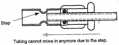
Fig. 16 Internal motion of the inserted tube is blocked by the addition
of an internal step.
[A small film of grease on the O-ring can ease sliding the O-ring onto glassware and help provide a better vacuum seal.]
The primary difference between a regular and a high-vacuum stopcock is the final grind. Stopcocks and joints are ground (lapped) with abrasive compounds just as rocks are ground in lapidary work. The finer the grade of grinding com pound, the smoother the finish on the ground (lapped) surface. The smoother the finish on the glass parts, the easier they will slide past each other when rotated.
Joints can be used for high-vacuum purposes without the same degree of grinding because they are not rotated.
Vacuum stopcocks are not meant to be interchangeable. Each plug and barrel receive their final grind together, and therefore they are mated for life. To prevent mismatching a plug and barrel set, numbers and/or letters are inscribed for each stopcock on the handles of the plug and on the side of the barrels (see Sec. 3.1).
Aside from alignment problems, cross-matched plugs and barrels of high-vacuum stopcocks may leak or jam when rotated.
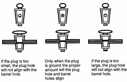
Fig. 17 Plugs of the wrong size can prevent flow in a stopcock.
- If the plug is too small, the plug hole will not align with the barrel hole.
- Only when the plug is ground the proper amount will the plug hole and barrel holes align
- If the plug is too large, the plug hole will not align with the barrel hole.
A simple, basic two-way glass stopcock (shown in Fig. 17) will have a single hole drilled through a solid plug. The arms are straight and placed 180° from each other. The plug is typically held in place by a rubber washer or metal clip at the small end. This stopcock design is easy to make and is inexpensive. The usual problems that arise from this type of stopcock are as follows:
1. Dirt can collect on the grease and work its way into the plug's hole.
From there the dirt can eventually wear a groove on the inside of the barrel. This groove, leading from one arm to another, can eventually become great enough to prevent a complete seal when the plug is rotated to the "off' position.
2. As stopcock grease becomes old and/or cold, it becomes brittle, and rotation can cause a "shear"-type break, allowing the plug to be free from the barrel.
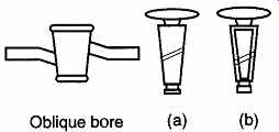
Fig. 18 Standard and vacuum designs of an oblique two-way stopcock.
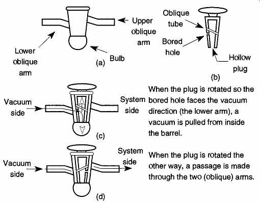
Fig. 19 How to evacuate the vacuum bulb of a vacuum stopcock.
By setting the two arms oblique to each other on the barrel and having a hole drilled diagonally in the plug (Fig. 18), two advantages are achieved:
1. If the first of the above problems arises, the grooves will not line up with the opposite arm and potential leakage is reduced considerably.
2. This configuration allows only one position (in 360° of rotation) for material flow.
As mentioned in Sec. 1.1.5, which discussed different types of glass, glass expands or contracts with temperature. Thin glass does not expand (or contract) the same relative amount as thick glass under the same conditions. Because of this difference, all vacuum stopcocks have hollow plugs so that the plugs may expand and contract at the same relative amount as the barrels. Thus, when there is a drop in temperature, the plug will not loosen by contracting a greater amount than the barrel. Likewise, if there is a sharp rise in temperature, the plug will not jam within the barrel by expanding a greater amount within the barrel. This quality can be critical if an experiment or environment has rapid temperature changes.
Figure 18(a) shows a solid plug. The holes in solid plugs are drilled.
Figure 18(b) shows a hollow plug. The hole in a hollow stopcock plug is a glass tube sealed obliquely within and later ground to fit the barrel. This inner tube pro vides the passageway for gases* through the hollow plug.
Oblique arm stopcocks are not immune from "shear" breaks caused by cold or old stopcock grease. Because an accidental rush of air into a vacuum system can cause damage to the system or destroy oxygen sensitive materials within the sys tem, vacuum stopcocks have a design feature to prevent accidental removal of the plug from the barrel. The stopcock design shown in Fig. 19 demonstrates how a vacuum stopcock uses a vacuum to secure its plug from slipping out of the barrel.
The bottom of the barrel is closed with a bulb [see Fig. 19(a)]. A hole is bored opposite the low opening of the oblique tube [see Fig. 19(b)]. Aligning the hole with the lower oblique arm of the stopcock [see Fig. 19(c)] creates a passage for the vacuum that holds the plug securely in the barrel. A 180° rotation from this position is the "open" position for this stopcock [see Fig. 19(d)]. The only way to separate the plug from the barrel is to release the vacuum from inside the stop cock by rotating the bored hole toward the lower oblique arm when no vacuum is present.
Figure 20 shows two different alignments of the same type of stopcock. This plug design is simpler, and therefore it is somewhat less expensive. There is no advantage of the "offset" design to the "L" design. The choice depends on how your system is built-that is, whether the "offset" design or the "L" design stop cock physically fits better into your given system or apparatus. With these stop cocks, the vacuum of the system holds the plug in continuously. However, once the system loses its vacuum, its ability to hold the plug is lost as well.
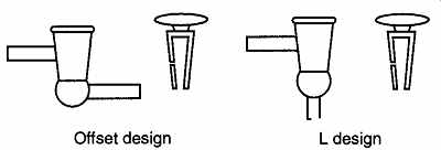
Fig. 20 The offset and "L" design of two-way vacuum stopcocks.
[Vacuum stopcocks are not intended for liquid transport use.]
2.2 Teflon Stopcocks
Teflon stopcocks provide excellent alternatives to standard glass stopcocks because no grease is required. They can be used in distillation systems where organic solvents, UV radiation, or oxidizing gases would normally make using a glass stopcock impossible. This advantage does not come without some cost because Teflon stopcocks are generally more expensive than standard glass stop- cocks. The Teflon stopcock design looks essentially the same as its glass counter part. However, it is not possible to take a Teflon plug and use it with a standard stopcock because Teflon stopcocks are made with a 1:5 taper rather than the 1:10 taper of glass. Because Teflon flows, or "creeps," it is likely to stick at a 1:10 taper by flowing into the arm holes, but far less likely to stick at a 1:5 taper. Teflon stop cocks with a 1:5 taper follow ASTM guidelines and are known as Product Standard.
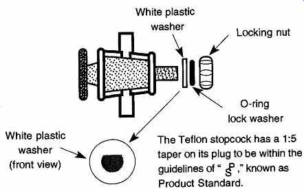
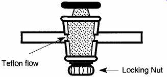
Fig. 21 Proper orientation of the parts of a Teflon stopcock.
There was a period of time when some Teflon stopcocks were made with 1:7 tapers, but this line was discontinued. I mention this point because some of you may have found one of these stopcocks and are having difficulty finding a replacement plug or are frustrated by trying to fit an old 1:7 plug in a new 1:5 barrel. The taper variations are small and subtle, so it is easy to confuse the two. Because the 1:7 taper design is no longer made, it is recommended that you phase any pieces with that design out of your lab.
The Teflon stopcock has more pieces (see Fig. 21) than the glass stopcock, and often the pieces are assembled in the wrong order. Inserting the plug into the barrel provides no challenges, but the white and black washers invariably get inverted. Each piece serves a specific function for the successful operation of the Teflon stopcock: The white washer helps everything on the plug shaft rotate together when the plug is turned; the colored locking nut helps maintain a certain amount of tension on the plug; and finally, the black washer (O-ring) serves as a lock washer to prevent the locking nut from rotating itself off the threaded section of the plug.
If the lock washer is placed on the plug shaft before the white washer, the washer's friction will grab the surface of the barrel and tend to make everything past the black washer not rotate while the plug is turned, causing the plug to tighten when rotated clockwise and loosen when rotated counterclockwise.
The white washer has a flat side on the hole through the center to maintain its nonslip position on the plug. Occasionally, the flat spot on the white washer becomes worn round, or a groove is worn into the threaded section of the plug.
Either of these effects causes the washer to not rotate with the plug and is the same as switching the positions of the black and white washer. Replace the washer or plug if either are worn.
2.3 Rotary Valves
Standard Teflon stopcocks cannot be used for any vacuum work. A completely different design from those discussed thus far is required for a Teflon vacuum stopcock. This design is shown in Fig. 22 and is called a rotary Teflon valve. It is called a valve instead of a stopcock because its operation and design is similar to those of a metal designed valve.
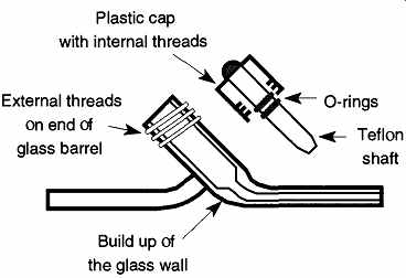
Fig. 22 The rotary valve operates by rotating a plastic cap. The rotational
motion of the cap is translated into linear motion on the Teflon shaft. When
the shaft is inserted all the way into the glass barrel, the tip of the shaft
pushes against a buildup of glass and stops fluid motion. The O-rings on
the shaft pre-vent leaks past the cap.
There are many designs of rotary valves: Some have externally threaded glass barrels, others have internally threaded barrels; some have exposed O-rings, others have covered O-rings, and some have no replaceable O-rings. Regardless, they all work with the same operational technique. Rotating cap motion translates into vertical motion on a central shaft, which rides up and down to open or close a pathway.
When closing a metal valve, it is customary to rotate the valve until it cannot be rotated anymore. Then you must give it a final twist to make sure it is closed tight.
This extra twist should never be done with glass rotary valves. These valves can not withstand the same forces as metal valves, nor is it necessary to use such force on a glass rotary valve. Glass is likely to break if too much torque is applied to the cap. Fortunately, because you can see through glass, it is easily possible to see if the shaft is closed against the barrel. This closed position is shown in Fig. 23 on the walls of the barrel with a "wet" mark.
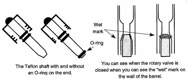
Fig. 23 The rotary valve plug with and without an O-ring on the end on
the left, and the shaft showing "wet" marks on the right.
- The Teflon shaft with and without an O-ring on the end.
- You can see when the rotary valve is closed when you can see the "wet" mark on the wall of the barrel.
Both Fig. 22 and Fig. 23 show O-rings on the Teflon shaft. Some manufacturers cover these O-rings with Teflon so that the rotary valve can be used with solvents that might otherwise destroy the O-ring. Others have "fins" that sweep in front of the O-ring to prevent solvents from contacting the O-ring.
Although all vacuum rotary valves have O-rings along the side of the shaft, some have O-rings at the end as shown in Fig. 23. This design has advantages as it provides a better quality seal without over tightening. The reason is simple: The same force applied over a small area will have a greater pounds-per-square-inch pressure than that applied over a large area.* With an O-ring at the end, it is possible to obtain much more force without having to bear down on the barrel and risk breaking the stopcock.
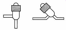
Fig. 24 General designs for rotary valves.
[This amount is analogous to the pressure exerted by spiked heels vs. running shoes on a sidewalk.]
All Teflon stopcocks and valves must remain free of particulate contamination so the surface will not be scratched or damaged. Any abrasions, or distortions, of the central shaft are likely to be leak sources. In addition, do not place any filled container closed with a Teflon stopcock (or valve) in a refrigerator. Just as Teflon expands in heated environments, it contracts in cooled environments. Thus, what was a good seal at room temperature may leak in a cold environment. Do not try to compensate for the cold temperature by overtightening the shaft for two reasons: One, it probably will not prevent a leak, and two, when it is removed from the cold environment, its expansion may break the apparatus.
Although the specific design of a valve varies between manufacturers, rotary Teflon valves are almost always a variation of the inline and right-angle designs shown in Fig. 24. Although the rotary design may be restrictive, it has provided new possibilities for valve design such as the Inlet Valve Chem Cap (shown in Fig. 25), which is designed for medium vacuum system use (up to approximately 10^-4 torr). The Chem Cap does not have a second or third arm as is customary with just about all other stopcocks because the transmission of gas is through the Teflon shaft itself. This stopcock can be used in place of a standard glass vacuum stopcock for grease free operations where a standard Teflon stop cock could not be used because of its inability to maintain a vacuum.
Another advantage of the rotary valve design is apparent when an extension from the end of the shaft is added and the valve becomes a needle valve. It can then permit fine control for the release or addition of materials (see Fig. 26).
Rotary Teflon valves have greater initial costs than comparable vacuum glass stopcocks. However, due to their lack of maintenance needs, as well as not requiring any stopcock grease, their long-term expense can be considerably less than that for standard vacuum stopcocks. However, because Teflon stopcocks or valves require a limited temperature environment, all glass stopcocks will always remain in demand.
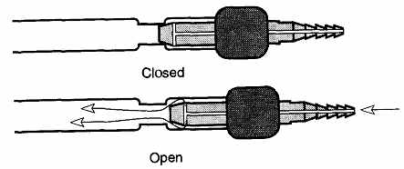
Fig. 25--Inlet Valve Chem Cap. The Inlet Valve Chem Cap is from Chem glass
Co. Inc., Vineland, N.J. 08360.
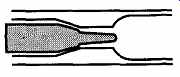
Fig. 26 A close-up of the end of the Teflon shaft with a needle valve
extension.
2.4 Stopcock Design Variations
All of the above designs are called two-way stopcocks because there are two arms, or connections, to the stopcock. Two-way stopcocks typically are open/ close valves with no proper orientation. The exception for this statement are the stopcock designs shown in Figures 18, 3.19, and 3.20, which require a specific orientation of the plug to the stopcock to evacuate the inside. There are no orientation requirements for rotary valves.
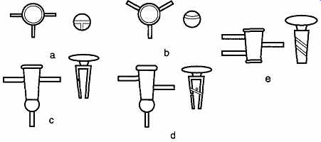
Fig. 27 Different designs of the three way stopcock, with the barrel on
the left and a side view or cross-section of the plug on the right.
Stopcocks with three arms are called three-way stopcocks. Five of the most common three-way glass stopcock designs are shown in Fig. 27. Represented are the barrel and plug cross sections (or end views) of three-way stopcocks. The three-way stopcocks (a), (b), and (e) are available in solid plug, Teflon, and high vacuum designs. The (c) and (d) designs are exclusively for vacuum systems and are currently difficult to find. Because of their design, rotary valves can only have two arms. It is possible to creatively place two of them together in a three-way alignment, however. An example of a three-way rotary Teflon valve configuration is shown in Fig. 28.
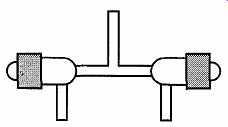
Fig. 28 A three-way Teflon rotary valve.
3. Maintenance and Care of Joints, Stopcocks, and Glassware
3.1 Storage and Use of Stopcocks and Joints
So much depends on the proper performance of stopcocks and joints that they should be treated with the same care, and consideration, as an optical lens. If your chemicals are stored in a volumetric flask, or held within a storage container by a stopcock, the material becomes worthless if you lose access to it because of a frozen stopper or stopcock.
Most occurrences of stuck stopcocks and joints can be prevented by proper storage, preparation (of the item to be used), application of grease (if required), and proper use. All of these points may seem obvious, but regrettably they are seldom executed. The greatest disasters I have seen from stuck stopcocks and joints occurred not from the original jammed piece, but rather from inexperienced attempts at separating the members, which often make it impossible to follow through on other separation approaches. For information on how to prevent joints and stopcocks from sticking, see Sec. 3.6. For a comprehensive list of stuck stopcock and joint separation techniques, see Sec. 3.7.
When putting items away for storage, the apparatus should be cleaned of all grease and then thoroughly cleaned so that all items are ready for use at all times.
Glassware should never be stored dirty with the intent to clean a piece before use.* In addition, dried grease and dirt often cause stopcocks and joints to stick. Finally, apparatus should be stored with all pieces assembled (note precautions in Sec. 3.2 and Sec. 3.3).
Stopcocks. After a stopcock has cleaned, a small slip of paper (measuring about 6 mm by 50 mm) should be inserted between the plug and barrel to prevent jamming (see Fig. 30). You may remove solid plugs and store them separately, but this storage is generally not recommended as it may cause future problems. For example, many manufacturers guarantee that their plugs are interchangeable. If the plugs are not interchangeable, the hole of the plug will not align with the holes of the stopcock. However, not all manufacturers are as good as their claims.
Regardless, plugs from one manufacturer seldom fit the barrels of another. If you have stopcocks from Kimble, Kontes, Corning, and Ace (to name a few) and do not wish to deal with trying to match plugs with barrels (and then try to match alignment, if necessary), store matched sets with a paper slip between the barrel and plug and be sure to match the plug and barrel with their respective code numbers.
[It is always more difficult to clean glassware that has sat for a period of time than it is to clean glassware that is recently soiled.]
Vacuum Stopcocks. Hollow plugs (with or without an open end) always indicate vacuum and should always be kept with their respective barrels. Vacuum stopcocks should never be stored with their plugs separated from their mated barrels. On the side of a plug and barrel is a numeric or an alphanumeric code that is used to match the two units. All high-vacuum stopcocks receive the final grind of the plug and barrel together, making them matched and individual. You should never cross-match high-vacuum stopcock parts, even if they seem to fit. If one or the other parts should be lost or broken, replace the entire unit. For storage, slip a piece of paper (about 6 mm x 50 mm) between the plug and barrel, then support the two parts together with a rubber band as shown in Fig. 30.
Teflon Stopcocks. Teflon stopcocks should never be stored with the locking nut tightened. Teflon flows under pressure, and such pressure could squeeze the plug up and into the holes of the barrel (see Fig. 29). Teflon plugs are tapered at a 1:5 ratio rather than the 1:10 ratio of glass stopcocks to help relieve some of these pressures.
If the barrel of a Teflon stopcock was designed too thin and the locking nut is left on too tight, any increase in temperature causing the Teflon to expand may cause the barrel to crack open into pieces.
The order of the washers on Teflon plug is important. As described in the previous section, after the plug is inserted in the barrel, the first piece to go on is the plastic washer, followed by the O-ring, which acts as a lock washer. The final piece to go onto the plug is the locking nut.
The hole through the plastic washer is not round; rather, it has a flat part on the hole (some manufactures use two parallel flat sections). This flat section matches a flat section on the threaded part of the Teflon plug and keeps the washer, O-ring, and locking nut as a unit to rotate with the plug when it is rotated. If this flat part wears round, the washer, O-ring, and locking nut do not rotate with the plug as it is turned. The result of this condition is that when the plug is rotated clockwise (CW), the locking nut (which is not rotating) tightens onto the plug. When the plug is rotated counterclockwise (CCW), the locking nut loosens from the plug. The occurrence of this phenomenon could be either just annoying or disastrous.
Teflon Rotary Valves. Teflon rotary valves should also be stored with the plug in place. The primary danger is to the plug which, if scratched, becomes worth less. The plug should be left screwed into the barrel, but never to the closed position. If the plug is screwed too tightly into the closed position, it is likely to place too much pressure on the threaded part of the Teflon, which, due to Teflon flow, will flatten out rendering the plug useless.
[Fig. 29 If the locking nut is left too tight, the Teflon will flow (over
time) into the holes of the barrel.]
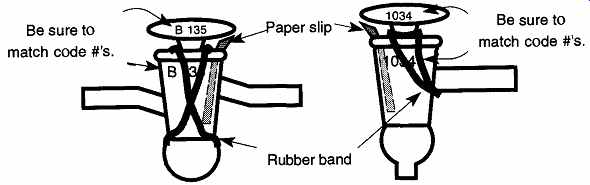
Fig. 30 When storing a high-vacuum stopcock, use a rubber band to secure
the plug onto its respective barrel.
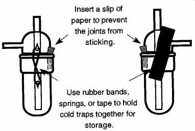
Fig. 31 Proper storage of apparatus will not only protect the joints,
but will also protect any internal glassware that could otherwise be broken.
Round-Bottom Flasks, Pennyhead Stoppers, Plugs, and Other Loose Items.
Many items are stored in drawers and (as the drawer is opened and closed) can bang around. This situation applies especially to round-bottom flasks, which are hard to prevent from rolling around. When these flasks bang around, star cracks, or flaws for future fracture, are created. For round-bottom flasks, Erlenmeyer flasks (on their sides), and other glass items that can roll, line the drawer with soft, irregular surface materials (like bubble pack), and, if possible, place cardboard dividers between the pieces. Finally, identify on the outside of the drawer what size flasks are stored within to limit the amount of opening and closing required.
Small, loose items, like pennyhead stoppers, should be stored by size and type in small boxes in a drawer. Occasionally you may have extra glass plugs from glass stopcocks (i.e., from broken burettes). These plugs also should be stored by size and type in small boxes in a drawer. Do not store Teflon stopcock plugs with glass stopcock plugs because the glass may scratch the Teflon leaving it worthless.
Wrap Teflon plugs in a tissue and then mark the tissue with its contents to help protect the surface of the plug as well as let people know the tissue's contents.
Cold Traps and Apparatus. Items like cold traps should be stored as complete units to protect the inner tubes. A small slip of paper (measuring about 6 mm by 50 mm) should be inserted between the inner and outer joints to prevent jamming.
If there are hooks, use a rubber band or springs to hold the parts together. If not, use masking tape to hold the parts together (see Fig. 31). Unfortunately, masking tape ages and loses its sticking abilities. Any remaining glue from old masking tape can be removed with acetone.
3.2 Preparation for Use
Any dust, fibers, or particulate material between the inner and outer members of a joint or stopcock can cause jamming and/or excessive wear on glass or scratch Teflon.
If you examine the cleaned plug from an old burette's stopcock (especially one from a freshman chemistry lab), you will see a lot of scratching and wear on either side of the hole. This wear is caused by particulate matter collected in the hole (see Fig. 32). In time, this wear circumscribes the entire plug, causing a leak that nothing can stop save replacement of the entire stopcock. Frequent cleaning (often not provided to freshmen chemistry burettes) can prevent unnecessary wear and subsequent problems.
All glass stopcocks and joints should have both inner and outer members wiped with a clean Kimwipe® before use to remove any particulate matter. In addition, to remove any fingerprints or other simple greases, a simple glass cleaner can be used to clean the glass. Rinse with water followed by a distilled water rinse.
Ground sections of high-vacuum pieces should not be handled after cleaning because perspiration can degas slowly within the system.
Teflon items (Teflon stopcock plugs, rotary valve plugs, and Teflon sleeves) should be wiped off with some acetone (using a Kimwipe) before being assembled for use.
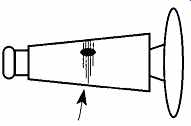
Fig. 32 Scratches on glass (or Teflon) plugs caused by particulate matter
collected on grease (and never cleaned) causes, scratches, or grooves on
a plug.
3.3 Types of Greases
When selecting a grease, keep in mind that a grease can only lubricate and/or seal. Stopcock grease cannot repair leaks or imperfections of damaged or poorly made stopcocks or joints. A grease's lubrication abilities are necessary for stopcocks to rotate, as well as to facilitate the easy separation of joint members. A grease's sealing abilities are necessary to help the joint or stopcock maintain the separation between a vacuum and atmospheric pressure, or between one (or more) com pound).
A sealant, such as Apiezon W, is a good example of a material that was designed for an extremely limited application. Apiezon W is a hard black wax that needs to be heated to 80°-90°C before it is soft enough to apply to the members you wish to join. At room temperatures it is hard and has no lubrication abilities whatsoever and is therefore not usable for a stopcock. It has a relatively high vapor pressure (10^3 torr), so it cannot be used for most vacuum work. However, at temperatures of about 100° to 150°C, it becomes very thin like hot honey and can easily be applied to joint members. Therefore, if you have a standard taper joint that will not be in a high-heat or ultrahigh-vacuum environment, there is no need to separate often, and you don't want it to accidentally separate, Apiezon W is the type of sealant you need.

Table 4 Hydrocarbon-Based Stopcock Greases
There are three types of stopcock greases: hydrocarbon-based, silicon-based, and fluorinated hydrocarbon-based. The general characteristics and attributes of the various hydrocarbon- and silicon-based greases are listed in Table 4 and Table 5, respectively (the third category, the fluorinated greases, requires no table because there are only two fluorinated greases, both made by the same manufacturer, and no cross distinctions are necessary). Table 6 lists the available technical information on all of the greases. These tables are by no means inclusive of all the greases available, nor is it complete. Regrettably, much technical information is not available. Occasionally, the technical information that was available was contradictory, and when this was observed, only the less grandiose of the claims was listed.

Table 5 Stopcock Greases Containing Silicone
Hydrocarbon-based stopcock greases are made (usually) from a refined hydro carbon base. They offer efficient sealing and good to excellent vapor pressures.
Some are refined specifically for stopcock use, whereas most others are made for the simpler requirements of joints. Most stopcock greases can be easily cleaned with hydrocarbon solvents, which is also part of their problem: Most solvents can easily strip the grease from a stopcock or joint. Working with solvents, solvent vapors, high temperatures, or UV wavelengths can break down organic stopcock greases (such as the Apiezon brand of stopcock grease). One option is to use a sil icon-based stopcock grease.
Silicon-based stopcock grease maintains constant viscosity over a wide range of temperatures (-40°C to 300°C). These greases are water insoluble and inert to most chemicals and gases. Silicone grease is inexpensive compared to many other stopcock greases.
There are, however, several drawbacks to using silicone grease: Silicone grease is not impervious to all solvents and ethers. Silicone grease ages rapidly and it breaks down under UV irradiation. Some brands of silicone grease begin to age once they leave the factory and are only good for about 18 months once you receive the tube. Old silicone grease becomes very hard, which makes rotation of a stopcock very difficult. When hard, silicone grease will not flow as a joint is being rotated. This lack of flow causes the grease to "crack," leaving a network of air lines (called a spider web). These air lines will leak to the environment or to the other sections of the stopcock. Despite its low vapor pressure, silicone grease "creeps" within a vacuum system, which can lead to poor visibility, make glass blowing repair difficult to impossible, and increase cleaning complications.
Both hydrocarbon and silicon-based greases show signs of aging, which are typically increases in viscosity. When hydrocarbon-based greases age, lighter factions of the grease evaporate leaving heavier factions of the same material remaining. Softening this material can be done by heat in the same manner that heat is used to soften cold honey.
When silicon-based greases age, light factions evaporate, leaving behind primarily nonvolatile components. Heat cannot soften this material. Thus, silicone grease requires more maintenance than hydrocarbon-based stopcock grease. For best results, old silicone grease can be (sufficiently) removed with a chlorinated hydrocarbon and new grease applied every two to three months. Reapplication of new silicone grease should be done regardless of whether a joint was used or not.
When silicone grease becomes hard, the material remaining is not the same material that has volatilized off. Thus, using a hot air gun (as one would use on hydrocarbon grease) for softening the remaining material cannot be used on silicone grease. You must replace the old grease immediately. Blowing a hot air gun on silicone grease with the intention to soften it up will in fact hasten its aging by removing the remaining volatile materials.
When all volatile compounds are removed from silicone grease, all that remains is silica. This material can be very difficult to remove from glass and can severely hinder any repair of glass items by a glassblower. Therefore, silicone grease must be completely removed before any intense heat (>400°C) is applied. Silicone grease can be removed from small systems by letting them soak in a base bath for a half hour.
The last grease type is fluorinated greases. These greases go under the brand name of Krytox® (registered and manufactured by Du Pont). They are all derived from the base oil Krytox 143. To this oil are added different amounts of a thickening agent and other materials that impart a variety of characteristics. The thickening agent for Krytox greases is a component of a compound related to Teflon, called Krytox® DR* Krytox DF is the lubricating agent used on all stainless steel razor blades. Krytox stopcock grease comes in two forms for common lab use: one for general use, Krytox® GPL, and one with low vapor pressure, Krytox® LPV(l(r 12 torr at 20 C).
Krytox seems like a product from heaven, as many of its attributes are spectacular. It is a fluorinated grease and is therefore impervious to hydrocarbon- and water-based solvents. It cannot burn, so it has no flash point and can be exposed directly to oxygen, even at high pressures. It can be used over the widest tempera ture range of all the greases and works equally well with stopcocks as with joints.
It has remarkable stability characteristics and can withstand long-term abuse. Best of all, Krytox greases are nontoxic.
There are, however, two problems with the Krytox greases. Although they do not burn, they break down in high heat environments (>260°C) into lethal fluorine compounds. Thus, a habit such as smoking while you work can truly become a real killer: If any Krytox grease remains on your hands when you handle a cigarette, burned Krytox fumes from the grease transferred to the cigarette can kill you. Because of the dangerous fumes generated by highly heated Krytox grease, it is obvious that any glassware contaminated with Krytox must be completely cleaned before any repairs can be made.
[Krytox DF stands for Krytox Dry Film. It was previously known as Vydax.]
The cleaning of Krytox grease presents the second problem. The removal of Krytox grease is problematic at best. Originally, the only way to remove Krytox from glass apparatus (or your hands), was to scrub it off (simple wiping is not sufficient) with a chlorofluorocarbon solvent such as Freon® 113 or Freon® TF.
Unfortunately, both of these compounds have been directly implicated in the destruction of the world's protective ozone layer and are no longer commercially available. But that wasn't all. If you simply tried to wipe off the grease with a small amount of Freon 113 or Freon TF, a joint or stopcock still wasn't safe. As mentioned before, the thickening agent for Krytox grease is called Krytox DF whose burning fumes are also toxic. Krytox DF can smear into the rough surfaces of a ground joint or stopcock, adding to the lubrication capabilities. To remove Krytox from these surfaces requires rough scrubbing with a toothbrush or finger nail brush and also requires sufficient solvent to remove the material.
To resolve these problems, the researchers at Du Pont tried a variety of cleaning solutions and eventually discovered that an industrial solvent, BH-38,* did a very effective job in removing the Krytox grease. The author did some basic tests and observed that the detergent did a good job of removing the vast majority of the grease. However, it was observed that an apparent film did remain on the ground section of the stopcock and joint, even with considerable scrubbing. The composition of this film is unknown at the time of this writing. The author plans a future experiment of heating the remaining material and determining the composition of any products. While there is no question that BH-38 is removing the Krytox, at this point in time the author is unaware of any independent studies verifying the safety of heating glassware, from which Krytox grease has been sufficiently removed, so that further glassblowing can be safely performed.
[It should be pointed out that there is nothing particularly special about this specific industrial sol vent, and others may work just as well.]
----------------------
Table 6 Technical Data Chart for Various Greases
" oftens at 250°C, but does not melt to a free flowing liquid.
* Apiezon greases are made in England and are sold by many suppliers.
c. Designed for ultrahigh vacuum.
d. Good for general use.
e. Designed for stopcocks.
•^Designed for high temperature uses.
s. Ultra high-vacuum use.
* Not leached by aggressive solvents, yet are removable with aqueous detergents.
' Moderate vacuum use.
' Fisher Scientific product.
* Heavier and darker than Cello-Seal, high-vacuum use.
' Gas tight seals between glass and rubber tubing; can be coated outside of tubing to pre vent diffusion.
m Dow Corning product.
" Constant viscosity in that temperature range.
0
General Electric product (Silicone Products, Waterford, NY).
p
Corrosion protection; heat sink.
q
Non-lubrication; dielectric grease.
r
Made by 3M and M.W. Kellog Co.
s
Made by E.I. Du Pont de Nemours & Co., Inc.
' Fluoronated grease.
" More refined than Lubriseal.
v
Contains silicone and graphite.
w
Made by Podbielniak.
x
----------------
Insoluble with most organic and hydrocarbon materials, but soluble in water.
Krytox, Teflon, and other similar products can be removed by incineration, and the amount of fluorine released from several stopcocks or joints is a relatively small amount. However, if the oven used is not properly vented in the confined space of the oven's room, the fumes could be toxic. At the time of the writing of this book, there are no environmentally safe solutions. Accordingly, those concerned about the environment may be inclined to conclude that there is no justification for using Krytox grease. However, Krytox is the only grease for stopcocks that can be used for very low temperatures (-35 °C) to very high temperatures (220°C), has a very high level of chemical inertness, and will not affect elastomers or metals. Thus, there are conditions when Krytox is the only viable alternative.
3.4 The Teflon Sleeve
There is one other substitute for stopcock grease on standard taper joints: the Teflon sleeve. These sleeves are like socks for your joints. Because they are made of Teflon, they are not attacked by solvents, alkalines, and most other chemicals.
Thus, they are wonderful for items like solvent flasks which are under constant fume or chemical contact. However, they are not capable of maintaining a static vacuum and should not be used for vacuum work. Thin Teflon sleeves are less expensive, but cannot take physical abuse. Heavier Teflon sleeves have a greater initial cost, but can be used over and over.
3.5 Applying Grease to Stopcocks and Joints
The concept of "if a little is good, then a lot is better, and too much is just right" is incorrect for the application of grease on stopcocks and joints. Excess grease can spread throughout an apparatus, creating a mess that can affect the work in progress, decrease the potential vacuum and the speed of obtaining a vacuum, and, worse, plug up holes in stopcocks, making them inoperative.
Stopcock grease is applied to the inner member of a joint or stopcock, inserted within the outer member, and then twisted and/or rotated to spread the grease throughout the rest of the ground surface. Applying a mild amount of pressure will facilitate an even application throughout a joint. The colder a joint, the more difficult the grease will be to spread. Lightly heating members prior to assembly will help create an even distribution of grease.
When applying stopcock grease to pieces used on vacuum systems, do not use your fingers because perspiration from fingers can result in slow degassing within the system, limiting your potential vacuum. If the grease is supplied in a flat metal tin or glass jar, use a wooden spatula to spread the grease on the inner piece.
Grease that is supplied in a tube (similar to toothpaste) is easy to apply by laying the grease directly on the inner member in lengthwise strips (see Fig. 33).
Regardless of the method of application, one to two strips is all that is necessary for very small joints and stopcocks (14/35 joints or 2-mm stopcocks), and up to four strips are merged for large joints or stopcocks (45/50 joints or 10-mm stop cocks).
Once the grease is applied, insert the inner member into the outer member, twist and/or rotate the inner piece until there is a thin, smooth film of grease between the two pieces. If the hole in the stopcock plug becomes filled with grease, remove the plug and, using the wooden stem of a cotton swab, push out the excess grease.
If you are regreasing a stopcock or joint, be sure to remove all old grease (from both members) before applying new grease. If a solvent is used to facilitate grease removal, let the solvent dry before applying the new grease or it may be prematurely aged by the solvent.
3.6 Preventing Glass Stopcocks and Joints from Sticking or Breaking on a Working System
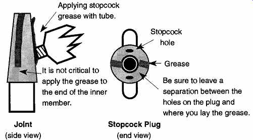
Fig. 33 The application of grease on a stopcock or joint.
Few things can be more frustrating, or economically devastating, than a frozen joint or stopcock preventing access to a compound. Part of experimental time should be spent making sure your equipment is ready to provide you safe and reliable use. Time for such preparation is part and parcel of experimentation.
Periodic removal and reapplication of stopcock grease is a must. The frequency depends on the size of the stopcock or joint, how often it is used, under what conditions it is used, and under what type of conditions it will be used in the future.
Conditions that can increase the need for cleaning and reapplying stopcock grease are age, heat, the continued use of hydrocarbons within a system, and constant exposure to UV radiation. Silicone grease should be changed as often as once every two months to every week, depending on the type and nature of use. Even if an apparatus is not being used, silicone grease ages and must be changed.
Because of the constant heating that large stopcocks often receive (to aid their rotation) and because heating helps to age and drive out the higher volatile components of stopcock grease, large stopcocks should be cleaned and new grease reapplied fairly often. Specific frequency for changing stopcock grease is difficult to provide because it depends on the amount of abuse and frequency of use. How ever, with constant use, hydrocarbon-based stopcock grease should be replaced about every six months. Some general tips for joint and stopcock maintenance are as follows:
1. Never force an item. The glass might not be as strong as you, and you do not want to find out the hard way. Also, forcing a stopcock or joint is more likely to permanently jam an item than to free it.
2. Never soak a joint or stopcock in a joined position with its mate in an alkali solution (i.e., a base bath). Alkali solutions should not be stored in apparatus that have ground sections (joints or stopcocks) because they are likely to jam them.
3. Never leave a piece of apparatus with a stopcock or ground joint with its mate in place in a drying oven.
4. Never leave a Teflon plug or stopcock in a drying oven. If over 280°C, fumes from a Teflon item in a drying oven can be toxic. If less than 280°C, the Teflon item will expand with the heat at a greater rate than the glass, causing the glass item to crack or break.
5. Always hold the barrel or free-standing arm of a stopcock when rotating the plug. The torque applied to rotate the plug may be greater than the torque necessary to snap the stopcock off the apparatus.
3.7 Unsticking Joints and Stopcocks
Even if you follow all the rules of storage, preparation, and use, it is still possible to have a joint or stopcock stick. The separation of these items, like cleaning glassware, is more an empirical art than a specific science. Perhaps it is pessimistic to say, but you should approach the unsticking of joints or stopcocks as if you had already lost the apparatus in question. If you are able to free them, you have gained. Otherwise, you cannot lose something that you have already lost. The general rules for unsticking joints and stopcocks are as follows:
Your objective is to soften, not remove, any grease between the mated members.
Never perform cleaning operations with solvents on mated stopcocks or joints.
Never let mated stopcocks or joints bake in a drying oven or soak in solvents that can dissolve the grease. If there is no grease, there is little hope in separating the pieces.
[For instance, do not heat a round bottom flask with a single joint opening closed off. Excess pres sure can cause the item to blow up.]
Flame Heat. You can heat the entire joint or stopcock with a large bushy flame from a gas-oxygen torch if (1) no Teflon is involved (a sleeve on a joint or Teflon stopcock), (2) the piece is open to air on both sides,* and (3) the piece does not contain a flammable mixture. First, be sure to wear heavy, heat-resistant gloves (such as gloves made with Kevlar), and safety glasses (didymium or AUR 92 glasses are recommended). Be sure to rotate the object, while in the flame, so that all sides of it are equally heated. The length of heating time is only for half a minute at most. After heating, remove the item from the flame and try to separate the pieces immediately. If this method fails, you may let the piece cool and try again. However, your chance of success goes down rapidly if the first attempt is a failure. In lieu of a flame, one can also point the steam from a steam line at the stuck item. This is obviously safer than the flame and can be used near flammable materials. However, it is somewhat less successful than using an open flame.
Electrical Conduction Heat. If the item is soft glass, such as the ground stop per section on a storage container (or even a perfume bottle), a softer heat is required. This heating can be done by wrapping bare copper or nichrome wire (18 gauge) tightly around the joint, leaving an inch or so of tail. If you heat the wire tail with a flame, conductance will heat the joint. If you wish to use a voltage regulator (such as a Variac®) to heat the wire, use nichrome wire that is insulated with nonflammable covering. Do not use copper because it does not have enough resistance (while trying to get the wire hot, you will draw too much current and likely blow a fuse), and make sure that the wires do not overlap. In addition, be sure to turn the Variac off before handling. The steam mentioned above can also be used on soft glass.
Chemical Soaking Solutions. If it is not possible to use the heat from a flame, there are a few soaking solutions that may help. Their chemical mixtures are as follows:
Solution #1
Alcohol (2 parts) Glycerin (1 part) Sodium chloride (1 part)
Solution #2
Chloral hydrate (10 parts) Glycerin (5 parts) Water (5 parts) 25% Hydrochloric acid (3 parts)
Soak the frozen joint or stopcock in either solution overnight or longer. Try to free the item with a moderate amount of force, never an overt amount of force. If either solution fails, try the other solution or either of the methods below.
[Bidymium or AUR 92 glasses are those used by glassblowers. They are obtainable from most of the manufacturers listed in Section C, Sec. C.I. Both of these lenses have special filtering properties which eliminate the sodium spectra, allowing the wearer to see through the normally bright yellow light emitted by glass. Sunglasses and welder's glasses cannot be used for substitution.]
Soda Pop. Surprisingly, soda pop has been used to successfully separate stuck stopcocks. Some people say you need to use stale cola, others say fresh cola. I've tried both with equally mixed success. Butler, using the fresh cola approach, suggested that the mechanism at work is the decomposition of carbonic acid as follows:
H2CO3 -> H2O + CO2
Butler also suggested that it is the resulting CO2 pressure that de-freezes the stuck stopcocks. Additionally, he suggested that there may be some interaction between the carbonic acid and various sites on the glass surface. On the other hand, the acidic nature of fresh soda (any fresh soda) is sufficient to dissolve lime and other hard water deposits. Thus, if the joint is frozen due to such deposits*, a fresh soda could ostensibly remove the deposit and defreeze the joint. Despite the loss of a good soda, it would be safer, but probably not as effective, than hydrochloric acid.
[Hard water deposits could happen if assembled glassware is placed in a sink of water and left to soak for an extended period of time.]
Regardless, neither of these suggestions explain why stale cola should work.
Whether fresh or stale cola, the joint needs to be soaked from 3 to 48 hours. If you choose to use the fresh cola approach, it should be replenished periodically to allow for fresh acidity and/or bubbles.
Beeswax. Heat the joint to just above the melting temperature of beeswax (about 65°C), then apply the wax at the lip of the two parts. The wax will melt and surface tension will cause the wax to penetrate between the male and female sections. Let cool, then reheat and the joints may separate.
The Vibrating Etching Tool.
First, remove the carbide tip from an engraving tool (to prevent damaging the glassware), and then place the vibrating end to the ground section while pulling on one of the pieces. You may also try to preheat the joint as mentioned above.
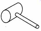
Fig. 34 A crab mallet.
The Crab Mallet. Even if glassware with stopcocks or joints is properly stored in drawers, occasionally the members may stick. The following de-sticking technique will work on dry (ungreased) items only. Use a wooden stick, or crab mallet (see Fig. 34), and lightly tap the stuck member in the same alignment as the joint itself (see Fig. 35). Be sure to lay the item on a table so that if you are successful, the item will skid on the tabletop a few inches rather than fall to the ground. The use of wood for this technique is important because anything harder is likely to chip, crack, or demolish the glass.
The False Handle. Finally, there may be times when part of a stopcock or plug has broken off, leaving little left to hold onto. This situation can make removal very difficult. Trying to grab onto remaining glass with a pair of pliers often is futile as the glass breaks and chips off. If there is access to the opposite end, it may be possible to tap, or push, the piece out. Alternatively, if the plug or joint is hollow and is closed like a cup, it may be possible to pour melted lead or melted electrical solder into the item like a screwdriver tip. Then when the melted metal hardens, you have a good handle with which to remove the remaining portion of the plug. The solder may then be removed and reused.
WARNING: Although the materials used in these unsticking techniques are, for the most part, inert or nonreactive, practice safe chemistry. If you have a chemical (that is trapped by a stuck stopcock or joint) that may react with one of the materials or solutions mentioned in this subsection, select a different approach.
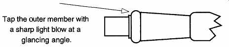
Fig. 35--Lightly tapping stuck (ungreased) joint or stopcock members with
wood can sometimes separate the pieces.
3.8 Leaking Stopcocks and Joints
There are three reasons that a joint or stopcock might leak: Either the item is not being used in the conditions, or manner, for which it was designed, the stopcock or joint is worn, or the item was poorly manufactured. Although extra grease may be used for short-term emergency situations, it is not a solution because extra grease is not fixing the problem. Similarly, adding extra stopcock grease to a regular stopcock will neither make it act like a high-vacuum stopcock nor help a defective stopcock or joint.
Surprisingly, many assumed defects of a joint or stopcock are caused by using an item improperly. By trying to "make do" with what you have, you either may jeopardize the quality of your work or may subject yourself and others around you to potential dangers. Thus, adding extra grease onto a standard stopcock to that it can be used for vacuum work will be a losing battle.
Assuming that the joint or stopcock selected is proper for the application and there is evidence of leakage, you should look for potential human errors:
1. Did you apply the stopcock grease properly, or is the current grease old?
2. Did you properly clean the items before assembly? Paniculate matter left in a joint or stopcock can not only cause a leak, but can also cause the stopcock to jam.
3. Are the pieces of a Teflon stopcock assembled in the correct order? For example, on a Teflon stopcock, if the black O-ring is placed next to the stopcock barrel, counterclockwise rotation may cause the plug to loosen.
4. If you have a vacuum system with glass stopcocks, do the numbers on the plugs and barrels match (see Sec. 3.3.1 and Fig. 30)? Even if failure to prevent the above errors has not caused a leak outright, pro longed misuse eventually causes wear on a joint or stopcock, which can then cause permanent damage. Not all defects caused by wear can be distinguished from manufacturing defects by appearance alone. However, if a new item leaks from structural defects, it probably is a manufacturing imperfection.
Although the quality of joint and stopcock construction from the glass manufacturing industry is generally excellent, mistakes do happen. It is possible to have received hundreds, or thousands, of excellent joints and stopcocks from the same manufacturer, plus one that leaks. Fortunately, manufacturers will promptly replace defective materials.
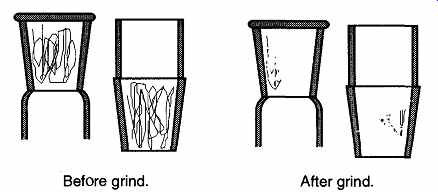
Fig. 36 Sample of using the pencil test to examine the quality of a joint.
The Rock or Jiggle Test. It is possible for a joint or stopcock to be so badly made that a mated pair can rock, or jiggle, when a little lateral motion is applied.
This test should be done without any stopcock grease on the pair to prevent artificial damping of the motion. Do not force or twist any joint without grease as it is likely to jam. The biggest problem with this test is that it is impossible to know which of the pair is the bad one. To use a pair with this problem will only make both pieces bad as the bad one will wear the good one unevenly, thus making it unusable.
The Pencil Test. Before performing the pencil test, completely clean the entire apparatus in question. Remove all traces of any oil or grease (if the grease is hydrocarbon-based, you can heat the glass item in an oven to approximately 400°C to burn off any remaining grease). Next, take a standard no. 2 pencil and scribble a line all over the inside surface of the outer piece and the outside surface of the inner piece, as shown at the left of Fig. 36. Then, wet the joint (or stop cock) members with water (for lubrication) and rotate back and forth five to ten times (do not bear down, let the water be a lubricant). If the ground sections of both faces of the joint (or stopcock) are perfectly flat, the pencil will have been removed while the two faces ground against each other. If there are any depressions or raised areas on either surface, pencil lines will remain or be selectively ground away as seen at the right of Fig. 36.
This technique works well with both regular stopcocks and joints, but the surfaces on vacuum stopcocks are ground so smooth that they are unable to grind off the pencil. However, by adding a very small amount of an optical finishing powder (i.e., aluminum oxide #50) you will be adding sufficient roughness without doing any damage to the stopcock. If there is too much of the optical finishing compound, the slurry will grind all the pencil off regardless of the quality of the stopcock. Use plenty of water for lubrication; a joint that becomes stuck with grinding compound is almost impossible to separate. Once you have finished using the grinding compound, be sure to thoroughly rinse it out. Grinding com pound left on a joint or stopcock is likely to destroy the item over time.
As previously mentioned, it is important that all oil and grease be removed before trying the pencil test. This point becomes even more critical if any optical finishing compound or grinding compound is used because it is likely to stick to any remaining oil or grease. If the stopcock is used with any particulate matter mixed in with the grease, it will grind into the glass and destroy the stopcock or joint.
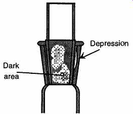
Fig. 37 Sample of using the Prussian Blue (or Merthiolate) test to examine
the quality of a joint.
The Merthiolate or Prussian Blue Test. The pencil test will not work on a Teflon stopcock because there is no rough surface with which to rub a pencil mark off. Grinding compound cannot be used because it will destroy the surface of the Teflon, thus destroying the plug. Rather than using a rough material to grind off a pencil line, this test uses either Prussian Blue or Merthiolate to collect in the depressed surface of the member. The item is cleaned as before, but this time several drops of Prussian Blue or Merthiolate are placed on the inner piece before assembly with the outer member. As seen in Fig. 37, any dark spots signify a thicker film of the indicating solution, which implies a concave impression on one or the other piece. A perfect joint shows clear with no dark areas. This test can also be used on glass stopcocks or joints. By rotating the two pieces you can note with which member the dark spot travels. If you hold the outer piece still, rotate the inner piece, and the spot travels, you know the depression is on the inner piece. Similar logic is used to identify depressions on the non-rotated piece.
3.9 What to Do About Leaks in Stopcocks and Joints
Unfortunately, there are not many options available when you have a defective stopcock or joint. The best solution is to replace the defective part of the apparatus, or the entire apparatus if necessary. If the item is new, return it to your sup plier and have it replaced.
If the defective part is the plug of a Teflon stopcock, you can try to simply replace the plug. If the plug was damaged by abrasion (or other abuse), replacement offers a simple resolution. The possibility that a distorted Teflon plug is causing a leak is very unlikely. If the glass barrel of a Teflon stopcock is distorted (showing the problems seen in Fig. 37), you have no recourse but replacement.
If the item is all glass, it may be reground. However, do not regrind a glass stop cock if:
1. You have any other recourse (see Point 5).
2. You are not experienced in grinding stopcocks or joints.
3. You are unable to completely remove all traces of oil or grease from the item. Any oil or grease will retain grinding compound onto the part, and subsequent use of the item with the grinding compound on it will cause it to jam or wear unevenly, leaving you back where you started. The best technique for removing organic greases is to burn them off in a high-heat oven.
4. If the item is a stopcock and the overlap of the holes on the plug and barrel are such that any grinding will close the hole passageway (see Fig. 17).
5. You can accept that the piece in question is expendable.
Grinding should be done with 120-grit Carborundum and plenty of available water. Adding a little dishwater soap will help lubricate of the pieces as they are ground.
After removing all grease, wet both glass members with water and place a small bit of grinding compound on one of the members. Insert the inner member into the outer member and, while applying a light amount of pressure, rotate the members around and around, not back and forth (this point is very important because back and forth rotation with grinding compound will cause uneven wear). Remember, incomplete rotation will mean that you are making a depression in only one region of the rotation. Never let the members become dry while rotating, otherwise they are likely to freeze. Members that freeze while grinding cannot be separated.
If you chose to regrind and you use a glass part with which to grind the errant member, the parts are "married" to each other and should be numbered like vacuum stopcocks. These pieces are likely to leak with any other similar-sized member.
3.10 General Tips
To facilitate the creation of a high vacuum, heating the walls of a system will help drive off moisture. On a glass system, this heating is typically done with a hot air gun. It is important that any heat source is not aimed at stopcocks or joints on the system. However, it is often necessary for very large stopcocks or joints to be heated before they can be rotated or separated. Therefore, pay attention and do not heat any more than necessary. These stopcocks or joints require frequent grease replacement. Do not dwell the hot air gun on any particular spot while the system is under any level of vacuum and the hot air gun is on full. It is possible for the glass to get sufficiently hot for air pressure to collapse the wall of the system. To prevent this, simply move the hot air gun as one would move a paint sprayer.
Keep in mind that if you heat a vacuum stopcock or joint in a vacuum influence, any grease on the member will be squeezed out because the pressure of the vacuum will pull the plug deeper into the barrel, causing the (now less viscous) grease to be squeezed out. After repeated heating, grease under these conditions will age prematurely and become so thin that it will be useless.
Very high heat (> 300°C) can cause organic greases to volatilize. Once the grease is gone, rotation or separation of the joint or stopcocks becomes very difficult to impossible.
Using high heat (> 350°C) with silicone grease can cause parts of the grease to volatilize, while leaving the nonorganic remains to form a hard, crusty deposit that makes separation or rotation of stopcocks, or separation of joints, impossible. The material remaining from overheated silicone grease can only be removed with hydrofluoric acid. Silicone grease at room temperature ages in two to three months. At higher temperatures, the grease volatilizes significantly faster and needs to be replaced even more frequently.
4. Glass Tubing
4.1 The Basics of Glass Tubing
The glass tubing often used in beginning chemistry labs is soft glass that can be worked with the flame of a Bunsen burner. The vast majority of the remaining glass within the laboratory is borosilicate glass.
From Table 8 through Table 14, most of the different types of tubing manufactured in the United States and Germany are listed. These tables list the various sizes of tubes available as well as their inside diameters (I.D.), volume [in mL/cm (with the tolerance of that volume)], and volume (in mL) of one half-sphere (rep resenting the rounded end of a tube). The next two columns indicate the number of pieces shipped per case, and the price per length of tube (based on the price of one tube when purchasing one case of that size tube at 1990 retail prices). The final column provides the maximum tolerable pressure which that size tubing can withstand, assuming a maximum bursting pressure of 750 psi. The reader should closely follow the information on pressure in glass tubing in Sec. 1.1.12.
Standard Wall Tubing (Table 8). This tubing is made in metric sizes (unless otherwise stated, all measurements on these charts are metric). The vast majority of all tubing seen in the laboratory is standard wall tubing.
Medium and Heavy Wall Tubing (Table 9 and Table 10). This tubing is made in English sizes, but with the push toward the metric system such tubing is now listed in catalogs in its metric equivalent (therefore, 1" tubing is listed as 25.4 mm). Both English and metric measurements are listed in both tables.
Special Wall Tubing (Table 11). This tubing comes in medium and heavy wall types, but there are fewer size selections. In addition, these tubings are not sold as "medium" or "heavy" wall. Rather, when ordering, you must specify the desired outside diameter (O.D.) and wall thickness.
Capillary Tubing (Table 12). This tubing is selected on the basis of its inside diameter (I.D.), also called its bore. Capillary tubing is sold in a continuous (and sometimes overlapping) range of bore sizes. The O.D. is seldom the deciding factor in selection.
Schott Glass Tubing (Table 13). This tubing manufacturer uses a different system for determining sizes. For one, this tubing is 1.5 meters long (approximately five feet). Secondly, it does not come in medium and heavy wall thick nesses based on the English measurement system. Rather, for each outside diameter, one, two, or three different wall thicknesses are available. Because of these differences, all calculations for volume and pressure previously made would not be relevant. Table 13 provides all the above information, but the tubing is not separated by wall thickness.
Schott Glass Capillary Tubing (Table 14). This tubing is similar to regular Schott glass tubing because several I.D.'s are available for each size O.D.
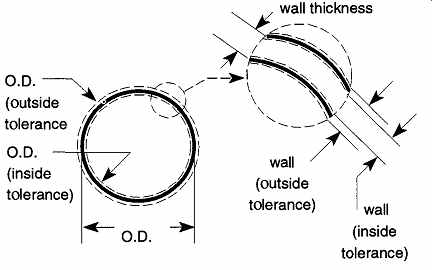
Fig. 38 The tolerances (±) of the wall thickness and glass tubing O.D.

Table 7 Ranges of Variations of Outside Diameter Due to Out of Round
4.2 Calculating the Inside Diameter (I.D.)
In manufacturing tubing, two out of three parameters-the outside diameter and wall thickness-can be monitored; the inside diameter (I.D.) is maintained through the manufacturer's control of the other two parameters. Therefore, the I.D. on all charts (except capillary tubing) is calculated by inference using Eq. ( 1):
O.D.- [2 x (wall thickness)] = I.D. ( 1)
Note that there are tolerances for each of these measurements, and each of these tolerances can cause variation in I.D. Figure 38 shows the potential variation.
Variations of the O.D. include any possible distortion of the tube diameter. This distortion is referred to as "out of round" or API (all points in). For example, 20 mm tubing has a potential variation of ±0.6 mm. The wall thickness for this tubing is 1.2 mm with a potential variation of ±0.1 mm. The range of variations can be seen in Table 7. Although there can be a range of 2.2 mm (+1.1) on the inside diameter of a 20-mm tube, most manufacturers maintain their tolerances within half of these amounts.
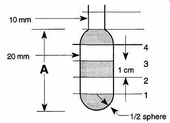
Fig. 39 Calculating the volume of a tube.
4.3 Sample Volume Calculations
With the use of Table 8 through Table 14, you can determine what size tubing may be required to satisfy a specific liquid volume amount, or whether the apparatus you have will contain a given liquid volume, by calculating the volume based on the O.D. of the container and its length.
For example, we can make a sample volume calculation using the information provided in Fig. 39 to determine the volume of "A." If the diameter of "A" is 20 mm tubing, we can see in Table 8 that the volume of the half-sphere is 1.4 mL and the volume of each centimeter is 2.4 mL; therefore the total volume is (2 x 1.4) + (3 x 2.4) = 10 mL. The centimeter of the 10-mm tube on the top can contain 0.50 mL.
Although tolerance is given for the volume per centimeter of tubing, no tolerance is given for the half-sphere. Because half-spheres cannot be formed with the same precision as with tubing, the volume measurement for half-spheres should be used only as a working tool and not as an accurate measure.

Table 8 Standard Wall Tubing
Table 11 Special Wall Tubing
Table 12 Capillary Wall Tubing
a. 1996 prices.
b. Maximum internal pressure is calculated on a variety of safety factors.
One of these factors is surface abrasion, which significantly lowers the potential pressure that a given tube can withstand. The use of safety shields and wrapping the tubing with fiber tape is strongly recommended. For more information see Sec. 1.1.12 c Because of the ranges in O.D. and Bore dimensions of capillary tubing, these two columns represent the extreme minimum and maximum bursting pressures based on the resultant variations of wall thickness.

Table 13 Duran Tubing Table 14 Duran Capillary ^ Wall Tubing
References
1. T.H. Black, "The Preparation and Reactions of Diazomethane," Aldrichimica Acta, 16, pp. 3-10 (1983).
2. D.W. Koester and G.A. Sites, "Method for Loosening Frozen Joints," Fusion, 20, p. 45 (1973).
3. E. Wheeler, Scientific Glassblowing, Interscience Publishers, New York (1958), p. 464.
4. J. Butler, "Carbonated Beverages and Frozen Stopcocks," Journal of Chemical Edu cation, 64, p. 896, (1987).
5. Pope Pacers (a publication of Pope Scientific), p. 7, Menomonee Falls, WI 53052 (January 1968).
6. R. Thompson, "A Method for the Removal of Stuck Ground Glass Joints," B.S.S.G. Journal, 24, p. 96, (1986).
7. C.H. Woods, "Removal of Broken, Evacuated Stopcock Plugs," Chemists-Analyst, 53, p. 53 (1964).