AMAZON multi-meters discounts AMAZON oscilloscope discounts
1. Compressed Gas Tanks
1.1 Types of Gases
A gas is defined as any material that boils within the general ranges of STP standard temperature (25°C) and Pressure (I atmosphere). Although there are many compounds that satisfy these conditions, only 11 elements do, and these are argon, chlorine, fluorine, helium, hydrogen, krypton, oxygen, neon, nitrogen, radon, and xenon.
There are two major groups of gases. The first group is known as the non-liquefied gases (also known as cryogenic gases). These gases do not liquefy at room temperatures nor at pressures from 25 to 2500 psig. They liquefy at very low temperatures (-273.16°C to ~ -150°C). The second group of gases, known as the liquefied gases, can liquefy at temperatures easily made in the laboratory (-90°C to ~ -1°C) and at pressures from 25 to 2500 psig. These gases become solid at those temperatures at which the cryogenic gases become liquid. Carbon dioxide (dry ice), generally considered a liquefied gas, could also be known as a solidified gas as it does not have a liquid state at STP.
As far as gas physics goes, there are only these two types of gases. However, the shipping industry has a third classification known as the dissolved gases. Acetylene is a dissolved gas, which without special equipment, can explode at pressures above 15 psig. Because of this property, efficient shipping of this gas becomes almost impossible. To avoid this problem, the gas is shipped dissolved in acetone and placed in cylinders that are filled with an inert, porous material.
Under these special conditions, acetylene can be safely shipped at pressures of 250 psig.
[A vapor is a gas that is near its condensation point within the general range of STP. ]
Gases are stored and shipped in a compressed state in cylinders designed to withstand the required pressure. The cryogenic gases, such as oxygen and nitro gen, are shipped in both liquefied and gaseous states, but the liquid state requires expensive equipment. Other gases, such as propane, are typically shipped and stored in their liquid states. The region above a liquefied gas is an area called the head space, which is the gas form of the liquefied gas. The pressure of the gas in the head space depends on the vapor pressure of the gas, which, in turn, depends on the temperature of the liquid gas. The greater the temperature of the liquefied gas is and the greater the amount of gas released from the liquid, the greater the pressure in the head space. If the pressure is sufficient, the container can rupture.
To prevent this, all tanks have some sort of pressure release valve that release excess pressure at some determined value.
To control the rate of flow and releasing pressure, gases are released from com pressed gas cylinders by regulators (see Sec. 2) at a user-defined pressure. A regulator can display the amount of gas remaining in a compressed gas tank (in cubic feet of gas), but not in a liquefied gas tank.
The remaining liquid gas in a tank can be estimated by observing any floats that may exist [most commonly seen in cryogenic tanks], but it can always be accurately determined by weighing the tank. First you must subtract the weight of the empty tank by the weight of the partially filled tank (known as the tare weight*) to determine the weight of any remaining liquid. Then you divide the difference by the weight of the liquid gas per liter to calculate the remaining volume.
Tank-weighing should be done with everything you plan to use with it (i.e., regulators, tubing, and so forth) attached, making sort of a "ready-to-use tare weight." This ready-to-use weight means you do not have to strip the tank of all equipment to make remaining gas determinations. Otherwise, if it was originally weighed without a regulator but later weighed with one, you might assume that you have more gas than really exists.
[All tanks that require weighing for volume content have their tare weight stamped on the side of the tank. This weight is exclusively the tank and does not include any regulators, valves, straps, or other fittings the user may have added. A tank of this size will contain (for example) 282 cu ft of oxygen, 257 cu. ft. of nitrogen, or 290 cu ft of ultrapure argon.]
1.2 The Dangers of Compressed Gas
Compressing a gas allows a lot of gas to exist in a small amount of area for transportation, storage, and use. It is physically easier to deal with a compressed, gas tank that is 9 in. in diameter and 51 in. tall than to store the approximately several hundred cubic feet of gas contained within.
Regardless of the inherent danger of any given gas, once a gas is compressed its potential for danger takes on a completely different light. A completely safe gas compressed in a container at some 2000 lb/in. ^2 could act like a bomb if improperly handled! Your safety, and the safety of your equipment, is therefore dependent on:
1. The quality of the maintenance and construction of the compressed gas cylinders
2. The materials and equipment selected to be used with the compressed gases
3. The proper use of the compressed gas cylinders and associated equipment
The first two points of the above list can best be controlled by strict industry standards and the conscientious matching of equipment to the needs and demands of the user. The third requires education, and unfortunately the user often does not have the opportunity (or desire) to learn everything there is to know about how to use compressed gases safely. Therefore, there have been a variety of industry standard "idiot-proof controls to minimize the possibility of mistakes. To make compressed gas cylinders consistently safe, reliable, and as idiot-proof as possible, these strategies took the study, analysis, and deliberation of at least 18 different private and governmental agencies (see Table 1).
----------------

Table 1 Agencies involved in Standardization of Compressed Gas Tanks
American Gas Assoc.
American Petroleum Inst.
American Society for Testing and Materials
American Welding Society
Association of American Railroads
Canadian Transport Commission (CTC)
Compressed Gas Association (CGA)
Compressed Gas Manufacturer's Assoc. Inc.
Connections Standards Commission of the CGA (This was first known as the Gas Cylinder Valve Thread Commission of the CGA. Later it became the Valve Standards Com. of the CGA, and in 1971 it received its current name.)
Department of Transportation (DOT)
Interdepartmental Screw Thread Commission
International Standards Organization (ISO)
National Institute of Standards and Technology (This is the new name of the National Bureau of Standards)
National Fire Prevention Assoc.
Standards Associations (representing Great Briton, Canada, and the U.S.)
U.S. Army
U.S. Dept. of Commerce
U.S. Navy
---------------
The first level of safety for quality and control is the construction of compressed gas cylinders. The specifications for their construction in North America is denned by Department of Transportation (DOT) and Canadian Transport Com mission (CTC) regulations. Cylinders are made from carbon steel or alloy steel with seamless, brazed, or welded tubing that is formed by billeting (drawing flat sheets to a cylindrical shape) or by using punch-press dies. Ends are sealed by forging or spinning at great heat. Alternatively, closed ends are drilled out and a metal piece is plugged into the hole. In the United States, one tank design can be used for a variety of gases (except for acetylene). In Europe, a tank can only be used for the gas it was designed for.
Generally, cylinders that are broad and squat in contour are for low-pressure service, such as the propane tanks used on automobiles or with campers. Those that are tall and thin are generally used for high-pressure containment, such as for oxygen, hydrogen, or nitrogen.
A series of letters and numbers are stamped on the shoulders of compressed gas tanks (see Fig. 2) to provide coded information for tank inspectors. These numbers tell under what codes the tank was made, the manufacturer, service pressure, serial number of the tank, and when it was last inspected and by whom. The manner in which the codes are laid out varies, and it may be difficult for an untrained person to interpret. However, to the compressed gas industry, they are important for preventing mistakes from the misuse of the containers.
1.3 CGA Fittings
To prevent gases from being attached to the wrong system, the Compressed Gas Association (CGA) implemented a variety of different fittings for attaching a regulator to a compressed gas tank. These fittings prevent a user from accidentally taking a regulator that is used (for example) for nitrogen and attaching it to a hydrogen tank. By itself, such an attachment may not seem too bad, but if the nitrogen regulator was already connected to a system expecting nitrogen, the con sequences of hydrogen could be dramatic.
Table 2 lists a number of gases and the appropriate CGA fittings or threaded connections that a regulator must have to be attached to a tank of such a gas (in this table, when a second CGA number follows a first entry, it is the CGA fitting for a lecture bottle). Alternatively, if you have a regulator and want to know what gases it can be used with-or what other gases use the same regulator--see Table 3.
If, after looking at Table 2 or Table 3, you wish to know what a fitting looks like, Fig. 2 illustrates the 15 most common CGA fittings used on full-sized com pressed gas tanks within the laboratory. Please note that right-handed threads close with CW rotation, and left-handed threads close with CCW rotation. Left handed thread fittings can be easily identified by the notch on the closing nut (see Fig. 2) as opposed to right-handed fittings, which are notchless.
Never spray or drip oil onto compressed tank cap threads to ease removal or to replace the tank cap. Minimally, the oil could contaminate the CGA fitting, but oil near compressed oxygen can explode! If you are unable to remove or replace a tank cap, obtain help from the manufacturer or the distributor of the compressed tank.
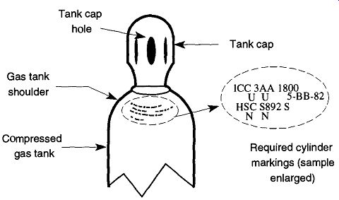
Fig. 2 An example of a compressed gas tank with cap.
Table 2 Common Laboratory Gases
Table 3 Common Laboratory CGA Regulators
1.4 Safety Aspects of Compressed Gas Tanks
Sections of a compressed gas tank are designed to provide safety for potentially abusive conditions. The most common structural protection is the tank cap, which is placed over the valve, then screwed onto the threaded neck of the compressed gas tank (see Fig. 2). In addition, you can obtain separate foot-rings that help a cylinder stand up, along with protective girdles for around the valve area.
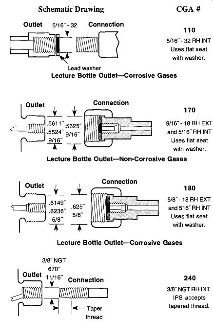
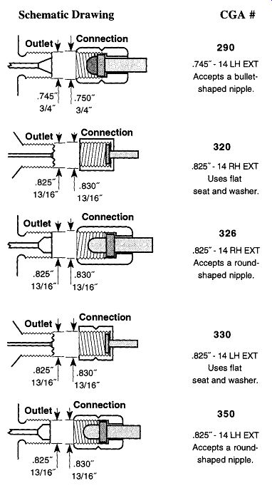
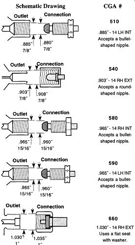
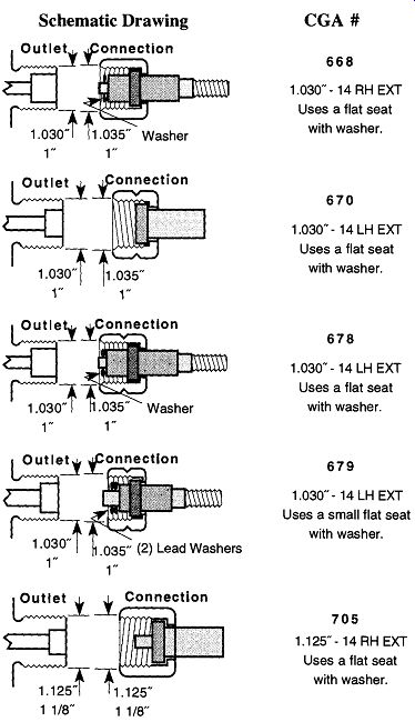
Fig. 2 CGA regulator attachment fittings.
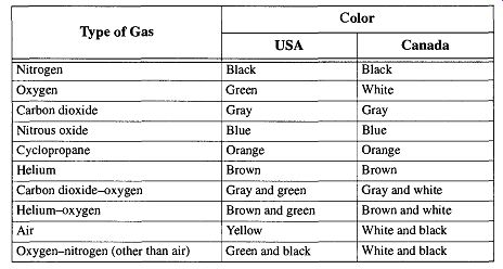
Table 4 Color Code of Medical Gas Cylinders
Tank caps can occasionally be difficult to remove. The easiest way to remove one is to insert a large screwdriver a short way into the tank cap hole (see Fig. 2), being careful not to make contact with the main tank valve stem. Using the screwdriver as a lever, it is simple to remove a tank cap (the cap should be rotated so the right side of the cap is rotating away from the observer). Sometimes it may be easier to place two screwdrivers (one in each hole). This provides equal lever age on both sides. Never use this technique to tighten a tank cap. Simply screwing on the tank cap by hand is sufficient-it is not necessary to forcefully tighten one down.
There are various color codes that are used with compressed gas tanks, but only the color codes of the medical gas industry are consistent. Note however, that the identifying colors from the United States and Canada are not consistent with each other (see Table 4).
Compressed gas tanks of large industries (or of particular gas distributors) are often color-coded by their own specifications for easy ownership identification and/or gas type recognition. You should never trust the color markings of com pressed gas tanks for identification unless the tank is used in medicine. The medical industries of both the United States and Canada have established color codes for medicinal gas tanks, but unfortunately they do not agree with each other (see Table 4). Otherwise, always depend on formal markings or labels for gas identification. If there is any question as to the contents of any compressed gas tank, do not use it; instead, return the tank to your gas distributor for identification and/or replacement.
Although the gas industry has not been consistent with color-coding (with the exception of the medical gas industry), is has agreed on warning signs with three specific signal words (see Table 1). The specific potential dangers associated with the various signal words are shown in Table 5.
Regardless of compressed gas tank construction quality, the printed warnings, and the various "idiot-proof arrangements, the user still must be aware of some basic safety rules when working with compressed gases and must be able to apply them with common sense to the dangers of compressed gases. There are two types of dangers when working with compressed gases: the danger presented by the specific gas you are using (flammable, toxic, oxidizing, and so forth) and the danger of having a metal cylinder under tremendous pressure standing a few feet from you. The next section details potential dangers that can occur during general use, and they also discuss appropriate responses. In addition to the general potential dangers of compressed gas tanks, you should also be knowledgeable to the potential dangers of the gas you are using.
----------
Table 1 DOT Signal Words
Danger: Warns the user that release of the gas in use to the atmosphere would pose an immediate hazard to health and/or property.
Warning: Warns the user that release of the gas in use to the atmosphere would not necessarily pose an immediate hazard, but would nonetheless be extremely hazardous to health and/or property under certain conditions.
Caution: Warns the user that there is no danger from the gas in use beyond the dangers associated with using any gas that is under high pressure.
-----------
1.5 Safety Practices Using Compressed Gases
Always Work in a Well-Ventilated Area. Perhaps the most subtle danger when working with compressed gases is asphyxiation. If one is working in an area with poor (or nonexistent) ventilation and there is a leak of a non-harmful gas (non flammable, nonpoisonous), then there will be a resulting decrease of the percent age (within air) of available oxygen.* This decrease can lead to asphyxiation.
Remember, propane is heavier than air, so in a basement situation, it settles and forces out the remaining air.
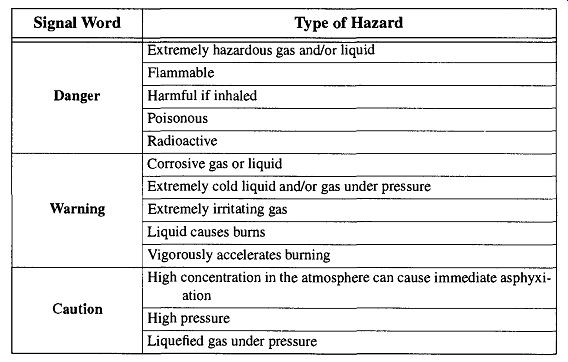
Table 5 Signal Words and Their Potential Hazards
The most insidious thing about asphyxiation is that it comes on without warning. There can be feelings of sleepiness, fatigue, lassitude, loss of coordination, errors of judgment, confusion, and even euphoria preceding unconsciousness.
Regardless, the victim will not be in a mental state to realize the danger and will be incapable of reacting properly, which involves getting out of the area to better air.
IN CASE OF EMERGENCY: Anyone going into a room suspecting low oxy gen concentrations should (1) arrange for a buddy system and (2) bring in portable breathing equipment. Gas masks or filters will not help in an oxygen-poor environment. Obviously, if you see someone lying on the floor there is a desire to run and help them. Unfortunately, that only places you in equal danger. Under no circumstances should you go into the room without calling the fire department, get ting help, and attaching a rope onto yourself so your backup can drag you out.
Because most modern labs have adequate ventilation, asphyxiation is seldom a problem. However, when work is being done in a basement, in rooms that do not have an adequate ventilation system, or when a gas is heavier than air, every pre caution should be taken such as the use of the buddy system, having portable air supplies available, and intercom systems with regular check-in times.
[Oxygen content in the atmosphere is normally about 21%. Because the partial pressure varies with the atmospheric pressure, the percentage of oxygen at higher altitudes will decrease relative to sea level. The flame of a candle will be extinguished when oxygen concentration is reduced to about 15% to 16%. A human will be rendered unconscious when oxygen concentration is reduced to about 12%. Prolonged exposure within a low-oxygen-percentage environment can lead to brain damage or even death.]
Always Secure Compressed Gas Tanks. A compressed gas tank should never be allowed to stand free. Instead, it should be supported by an approved tank sup port and the screws should be tightened by a wrench, not just by hand. If lying horizontal, the compressed gas tank should be prevented from rolling.
Just about everyone has heard stories of compressed gas tanks being knocked over, thus snapping off the main valve, turning the compressed gas tank into a rocket. The Compressed Gas Association claims that this orifice is too small for the tank to become a projectile. However, if the tank contains a flammable gas, the question of whether the tank will turn into a rocket is of secondary importance.
Even when a compressed gas tank is empty, it should be strapped down. The standard compressed tank used in most laboratories weighs about 100 and could be quite destructive if it were to fall over onto something or someone. While the west coast is vulnerable to earthquakes, any lab is susceptible to the clumsy or accidental actions of a person knocking over a tank. It is now a safety standard for compressed gas tanks to be supported by two straps about 2-3 feet apart, as opposed to the previous standard of a single strap. The reason for this is that occasionally the tank's footing would slip, allowing the tank to slip out from underneath the single strap. This second strap should be mandatory in earthquake areas.
It has been the author's experience that the standard clamp-on design of com-pressed gas tank support proved to be very unreliable in a powerful earthquake.
Permanently bolted, double-strapped supports have shown to be very reliable.
Keep Electric Lines Free from Compressed Gas Tanks. Compressed gas tanks are made of metal. Keeping electric lines away from compressed gas tanks helps to prevent spark development and potential shock to the user.
If you should come upon someone who is frozen by electric shock to an electrified compressed gas tank, do not handle the person with your bare hands. First, if possible, quickly ascertain the source of the electricity; and if it is safe and easy to stop the current, do so. Otherwise, be sure you are not standing on, or in, water, and use something that is nonconducting (e.g., a broom handle) to pull the victim from the electrified tank. Call for medical attention immediately.
If a tank regulator is connected to metal tubing that in turn is connected to any type of equipment, the tubing should be grounded (for example, to metal piping).
This grounding can be done with bushing wire, or any heavy-gauge wire, and a screw clamp.
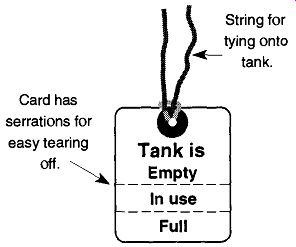
Fig. 2 Suggested card to be placed on compressed gas tanks.
Keep Compressed Gas Tanks Away from High Heat. Compressed gas cylinders should not be subjected to atmospheric temperatures above 130°F. A com pressed gas cylinder should never be subjected to a direct flame. If defrosting an iced or frozen tank, water above 130°F should not be used. If compressed gas tanks need to be left outside, they should be kept in a shaded environment.
Compressed Gas Tanks Should be Properly Moved. Compressed gas tanks should never be dragged, slid, or allowed to bang against one another. One should use a proper hand-truck or other suitable device for transporting the specific type of compressed gas tank. Compressed gas tanks should never be lifted by their caps, by magnets, or by ropes, chains, or slings unless the manufacturer has pro vided attachments (such as lugs) on the tanks.
Compressed Gas Tanks Should Be Properly Stored. When a variety of different gases are to be stored together, they should be separated by type. For example, combustible gases should never be stored directly next to sources of oxygen. They should also be separated as to whether they are full or empty. After a tank has been emptied,* it should be marked to make its status easily identifiable. One technique is to take a chalk, or crayon, and write "M T" on the tank signifying that the tank is "empty." Unfortunately, not all gas companies wipe this mark off; thus after the tank is returned, a full tank could be displayed as "empty." A better technique is to loosely tape a piece of paper saying "empty" onto the tank. This paper will be removed by the gas company. Some compressed gas suppliers provide tags that can be hung on tanks which provide convenient identification of the gas sup ply (see Fig. 2). If you cannot obtain these tags from your supplier, they are very easy to make.
When you empty a tank, other people's confusion and frustration can be pre vented if you detach the regulator and identify the tank as empty before you call your gas people requesting a fresh tank. Likewise, if you need to remove the regulator on a partially emptied compressed gas tank, replace the protective cap and label the tank to indicate it is not a full tank, noting the remaining partial pressure.
Although it is not dangerous to store acetylene tanks on their side, such positions may allow solvent loss, which in turn can decrease the flame quality.
1.6 In Case of Emergency
In the United States there is an organization called CHEMTREC ( Chemical Transportation Emergency Center) that has a 24-hour toll-free number to call for advice on chemical transportation emergencies [(800)-424-9300]. For written or general questions, write:
Chemical Transportation Emergency Center
1300 Wilson Blvd.
Arlington VA 22209 or call (703) 741-5000
For information on the rules and regulations of transporting various gasses, con tact:
Department of Transportation Office of Hazardous Materials 400 7th St. SW Washington DC, 20590 (800) 467-4922
[A tank with less than 50 psig should be considered empty. It is not recommended to totally empty a tank because a completely emptied tank can develop condensation that can prematurely age the tank.
A tank should have either a regulator or a cap on. No tank should be left with the valve opening exposed to the environment.]
For questions specifically related to compressed gases, you may write or call:
Compressed Gas Association, Inc.
1725 Jefferson Davis Highway, # 1004 Arlington, VA 22202-4102 (703) 412-0900
Canada has a similar organization for chemical transportation emergencies, called TEAP (Transportation Emergency Assistance Plan). It is operated as a public service by the Canadian Chemical Producer's Association through the cooperation and aid of the member companies who operate the Regional Response Centers (RRCs) throughout Canada. They are also available on a 24-hour basis. However, you need to call the center in the Canadian region where you are located. For further information about handling and/or shipping pressurized containers within Canada you can write to:
The Canadian Chemical Producers Association 805-350 Sparks Street Ottawa KIR 7S8
1.7 Gas Compatibility with Various Materials
Gases can react with containers and tubing as well as with each other. The degree of reaction can range from premature aging to explosion. It is always best to pre vent a possible reaction than to repair the damage of one. For example, Table 6 indicates that chlorine will not react with an O-ring made of Viton, but will with the others listed. Table 6 also indicates that acetylene will react with zinc and copper, but does not indicate that acetylene can also react with silver, mercury, or the salts of either of these compounds. Because it is impossible to list all gas and material combinations, you should check with your gas supplier for compatibilities of any gas and material before committing yourself to full-fledged experimentation, even though the information should be on the MSDS sheets.
Table 6--Compatibility of Various Gases and Materials
This chart has been prepared for use with dry (anhydrous) gases at normal operating temperatures of 70°F (21°C). Information may vary if different operating conditions exist.
Systems and equipment used in oxidizer gas service (e.g., oxygen or nitrous oxide) must be cleared for oxidizer service.
S-Satisfactory for use with the intended gas (dry anhydrous) at a normal operating temperature of 70°F (2PC).
U-Unsatisfactory for use with the intended gas.
C1 through C7-Conditionally acceptable for use with the intended gases as follows:
C1-Satisfactory with brass having a low (67-70% maximum) copper con tent. Brass with higher copper content is unacceptable.
C2-Satisfactory with acetylene; however, cylinder acetylene is packaged dissolved in a solvent (generally acetone) which may be incompatible with these elastomers.
C3-Compatibility varies depending on specific Kalrez compound used. Consult E.I. DuPont for information on specific applications.
C4-Satisfactory with brass, except where acetylene or acetylides are present.
C5-Generally unsatisfactory, except where specific use conditions have proven acceptable.
C6-Satisfactory below 1000 psig.
C7-Satisfactory below 1000 psig where gas velocities do not exceed 30 ft/ sec.
I-Insufficient data available to determine compatibility with the intended gas.
2. The Regulator
2.1 The Parts of the Regulator
A compressed gas tank, when filled, may contain up to 2500 lb/in.^ 2 of pressure. These tremendous pressures cannot be throttled by the main tank valve to pressures that are usable in the laboratory. All the main tank valve can do is release or prevent the release of gas, not control the pressure with which a gas is released. A regulator is required to reduce the gas pressure in a controlled, stable, consistent, and reliable manner.
There is one valve and one or two gauges on a standard high-pressure regulator.
Figure 4 displays a typical fully equipped regulator. The components are described in the following sections.
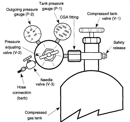
Fig. 4 Parts of the regulator.
The Compressed Tank Valve or Main Valve (V-l). This valve is not part of the regulator, but is part of the compressed gas tank itself. It rotates CCW for open and CW for closed (just like a water faucet). All this valve can do is let gas out (or in for filling). It cannot vary the pressure of the releasing gas. If the tank valve is to be used for a long period of time (days), it is best to open this valve completely.
This position presses part of the valve against an internal seal to prevent leakage past the valve stem. When using the compressed gas tank for short periods of time (hours), the amount of leakage is negligible, and several revolutions of this valve are sufficient. Never open the main valve of an acetylene tank more than one and one-half revolutions, and always open it slowly.
The Tank Pressure Gauge (P-1). This gauge displays the pressure inside the tank. It represents the pressure coming into the regulator. This gauge is not necessarily on all systems, especially those that have a constant pressure, such as a house air pressure system (see Fig. 2) or those with a liquefied gas such as pro pane.* This gauge is used to measure the pressure remaining in the compressed gas tank. Thus, if you notice you are low on gas, you can make arrangements for tank replacement before an experiment has begun (and thereby avoid problems or an emergency situation). It is a good idea to observe the amount of gas you use per experiment or per day to better estimate your needs. This practice can prevent the downtime of waiting for a fresh tank caused by poor planning.
[Gauges on liquefied gas tanks, such as propane, cannot indicate the remaining gas or the amount of gas used over a period of time. These tank pressure gauges only indicate the pressure of the gas (above the liquid) within the tank known as the head pressure. Volume of remaining gas must be determined by comparing the weight of the tank against its tar pressure]
The Pressure Adjusting Valve (V-2). This valve adjusts the pressure that leaves the regulator. It rotates CCW to decrease pressure and CW to increase pressure, which is exactly the opposite from a water faucet and can potentially create a dangerous situation. Before opening the tank valve (V-l) on a system that has more than one user, it is best to assume that the outgoing pressure is wrong. If someone had inadvertently rotated this valve CW with the intention of closing the flow, it would have actually opened the valve to full pressure. This could easily destroy hoses, connections, glassware, or anything else on the line. To prevent this from occurring, rotate the pressure adjusting valve CCW until it turns free.* Open the tank valve, then rotate the pressure-adjusting valve CW to the desired working pressure. Note: The pressure from the regulator cannot be decreased unless gases are being released from the system. Therefore make sure that the needle valve (V-3) and any other gas flow valves are open to the atmosphere at least a small amount when attempting to decrease the regulator pressure The Outgoing Pressure Gauge (P-2). This gauge displays the pressure that is set by the pressure adjusting valve (V-2). If you are trying to decrease the pressure and do not see any change, be sure the system beyond the regulator is open to the atmosphere (see previous subsection).
The Needle (Flow Control) Valve (V-3). This valve controls the volume of gas leaving the regulator. It rotates CCW to open and CW to close. If the regulator is connected to a glass system and/or rubber tubing, this valve should be closed when first opening up the pressure adjusting valve (V-2) to prevent damage to the system from too great a pressure. The needle valve (V-3) should be fully open if the system has a second needle valve further down the system, such as the valve of a glassblowing torch. The needle valve is not on all regulators, but can easily be added or removed.
The Hose Connection. This connection is called a barb by the welding and gas industry and is seldom on the regulator when purchased. Like the needle valve it can be easily added or removed. Alternatively, copper or high-pressure tubing can be attached directly to the regulator (with the proper fitting), which provides a more secure connection than that which can be obtained by forcing plastic or rubber tubing over a hose connection. If you need to order a hose connection, be sure to order a left-handed threaded nut if it's to go onto a tank for combustible gas.
[If you turn it too far, it will unscrew from the regulator. This is not a disaster; simply re-screw it back in several turns CW.]
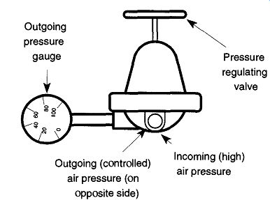
Fig. 2 Typical regulator used with a constant gas source such as house
compressed air.
There are two types of regulators: single- and two-stage (sometimes called double-stage). Both work on the same principle of (a) gas pressure pushing on one side of a diaphragm and (b) the pressure adjusting valve pressing a spring against the other side of the valve. The greater the spring pressure against the diaphragm, the greater the gas pressure available to leave the regulator. However, in a single stage regulator, as the pressure within the tank goes down, you must back off the spring pressure (using the pressure adjusting valve) to maintain the same outgoing pressure. Otherwise the outgoing pressure slowly increases as the tank pressure decreases. The two-stage regulator avoids this problem by having two single-stage regulators linked end-to-end. The first maintains an outgoing pressure between 350 and 500 psig, which is the incoming pressure of the second. Because the pres sure between the first and the second stage remains very consistent, the outgoing pressure is held equally consistent throughout the life of the tank. In addition, single-stage regulators typically cannot deliver large quantities of gas at high pres sure. Any attempts to push a single-stage regulator beyond its capabilities typically result in a loud wailing sound from the regulator.
2.2 House Air Pressure System
It is common for labs to have a high air pressure system built into benches, fume hoods, and other parts of the building. Sometimes the air pressure is too powerful for equipment to be attached. A simple regulator (see Fig. 2) can be attached directly on such a system using pipe fittings.
2.3 How to Install a Regulator on a Compressed Gas Tank
A few minutes of preparation will save you hours of cleanup time, replacement of equipment, and/or serious injury. Therefore, be sure to follow this general procedure:
1. Examine the edge of the regulator CGA fitting to determine whether the thread is right- or left-handed (see Fig. 2). Use an open end wrench, or large crescent wrench, to remove the regulator from the emptied tank. If the nut is notchless, it is a right-handed thread. If that is true and you are staring at the regulator and tank so that they are in the same orientation as in Fig. 4, the wrench should be placed so that the end is facing out from the page. To release the regulator, move the end of the wrench upward. An upward whack with the palm of the hand may be necessary to start the movement. Once loose, it should be possible to support the regulator with one hand and finish removing the nut with the other.
2. Strap the new, full tank securely into its proper position. Even though the old tank is empty, it should also be secured with the same level of safety. Full or empty, these tanks are heavy; and if they are accidentally knocked over, they can still do a lot of damage.
3. Examine the CGA threads of the tank and of the regulator to be sure that they are free of dirt, dust, and grease. [If there is any grease on the threads of the tank, return the tank to the supplier. If there is any grease on the threads of the regulator, return it to an authorized repair dealer.]
4. Stand to the side of the tank and quickly crack open and close the main tank valve. This action will force out any dust, dirt, or other particulate matter from the valve seating before you attach the regulator.
This matter, if not removed, can get into the regulator and either shorten the regulator's life span or get into the area where you are trying to deliver "clean" gas. Do not stand in front of the valve port and be sure that the valve port is not aimed at anyone or anything. The force of air can easily blow papers or glassware a considerable distance.
5. Attach the regulator to the new tank tightly with a wrench as mentioned in step 1, except tightening would be done by moving the end of the wrench toward the operator. Be sure to follow the direction of the threads. The fitting should be snug. Remember that the part of the CGA fitting that actually makes the seal is the end of the fitting. The threads are only securing the fit, and any leakage will not occur at the threads. Therefore, overtightening of the threads will not assist in any leak prevention. Use of plumber's Teflon tape will not hurt anything, but it will also not help ensure against leakage.
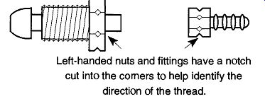
Fig. 2
Samples of left-handed nuts and fittings. Left-handed nuts and fittings have
a notch cut into the corners to help identify the direction of the thread.
2.4 How to Use Regulators Safely
Always open the main tank valve slowly. Intense pressure against the regulator's diaphragm can cause premature wear and aging. In addition, after the main tank valve has been turned off, the regulator should not remain under pressure for extended periods of time (i.e., several hours or beyond). The procedure of closing the tank valve (V-l; see Fig. 4) and then bleeding the system to release any remaining gases will help extend the life of the regulator. This bleeding procedure is more critical with two-stage regulators which may trap a small quantity of gas within the first of their two stages. This gas can then burst out unpredictably and potentially dangerously.
Another practice for extending the life of a regulator is to unscrew (CCW) the pressure adjusting valve (V-2; see Fig. 4) before opening the tank valve (V-l; see Fig. 4) and before setting the regulator to the desired pressure. In addition, open the tank valve slowly to limit the amount of shock on the diaphragm. Continued shock on the diaphragm causes premature aging.
When opening the main tank valve to allow gas into the regulator, you should stand to the side (not in front or behind) of the gauges, preferably with the main tank valve between you and the regulator. If an old worn diaphragm bursts during the sudden pressure increase, glass and metal shards could spray out. This damage cannot happen if the pressure adjusting valve is unscrewed before you open the main valve because there is no pressure against the diaphragm.
Never use oil in or around a regulator. Oxygen regulators (CGA fitting 540) pose special dangers because oxygen decreases the ignition temperature of flammable materials. Oil around compressed oxygen can explode. Do not use plumbing "pipe dope" on a CGA fitting. If a CGA fitting needs "pipe dope," there is something wrong with the fitting and it should not be used.
Do not use a regulator that has been dropped or shows any signs of physical abuse. If in doubt, have the regulator checked at the manufacturer's service center.
When storing a regulator, place it in a plastic bag to prevent dirt and dust from settling on, and in, the regulator. Dust and dirt can damage the diaphragm, or wedge within the sections, preventing complete closing of the diaphragm parts. Regulator cleaning and repair should be done by a service agency and should not be done by inexperienced personnel.
2.5 How to Test for Leaks in a Compressed Gas System
The first leak to check is within the regulator: To see if there is gas leakage past the diaphragm, rotate the pressure adjusting valve CCW until it is fully open, then slowly open the main tank valve. If any gas leaves the regulator, the regulator is defective or broken and needs repair or replacement.
To see if you have a leak within the line of your pressure system, close all nor mal outlets. Then, after opening the main tank valve and rotating the pressure adjusting valve (V-2; see Fig. 4) to the desired pressure, turn the main tank valve off. If you see a dropping off of pressure on the tank pressure gauge, you have a leak somewhere in your system.
To limit the region needing examination, rotate the pressure adjusting valve CCW one or two revolutions. If the reading on the tank pressure gauge drops, there is a leak in the compressed tank valve, the CGA fitting, or the tank pressure gauge. However, if the outgoing pressure gauge drops, there is a leaky outlet fit ting, needle valve (if any), outgoing pressure gauge, hose, tubing leaving the regulator, or any other part of the system beyond the regulator. Finally, if the tank pressure gauge drops and the outgoing pressure gauge rises, there is a leak in the regulator itself. (It is normal to see this last pressure rise when you are bleeding the pressure from a single-stage regulator just as the pressure in the regulator is almost extinguished.) If you know you have a leak but are not sure of the location, do not use a flame to aid your search. If the gas is flammable, the dangers are obvious, but otherwise there is concern of burning parts and equipment. The best and safest technique is to spray, squirt, or drip a soapy water solution on the suspected area. Use either a diluted liquid dish soap or a commercial solution such as Snoop®.* The evidence of bubbles is a sure sign of a leak. However, be sure you witness bubble formation as opposed to bubbles just sitting there, which are likely to have formed during the application of the bubble solution.
2.6 How to Purchase a Regulator
Most regulators can provide uniform and accurate high-pressure output. Where regulators vary is in their output potential. A large gas demand requires a regulator with a large output potential. By selecting a regulator that only satisfies the mini mum flow rate for your expected needs, you may be unable to achieve unexpected high-flow demands.
A wailing noise coming from your regulator is a symptom of using a large quantity of gas at a rate faster than the diaphragm within the regulator is capable of supplying. Unless you are able to use a smaller quantity of gas, the best solution is to purchase a larger regulator with a higher flow capacity (typically a two stage regulator) and/or a better quality regulator.
If you absolutely need constant outgoing pressure, regardless of varying tank pressure or the varying rate of outgoing gases, select a two-stage regulator; other wise, a single-stage regulator is sufficient. Although the changes are subtle, single-stage regulators have less stable outgoing pressures as tank pressure drops or as you increase the rate of outgoing gases. If you are using a corrosive gas, it is imperative to use a stainless steel regulator. Otherwise, a brass regulator is sufficient.
[ Some people use the flickering of a flame as an indication of a leak. Liquid dish soap can corrode stainless steel, so rinse it off when completed. SNOOP®, Product of the Nupro Company, Willoughby, OH 44094. ]
When you order a regulator, expect to receive only the regulator. Unless you specify that you also want a needle valve and/or a barb (hose connection), you probably will not get one! Be sure to ask the salesperson what you will be receiving with the regulator. This information becomes more important if you are ordering a regulator for a tank that has a left-handed CGA fitting such as a propane tank, because all the fittings for this regulator will also left-handed. If you wish to add a hose connection onto the regulator after it has arrived at your lab, you might end up digging through drawers filled with right-handed fittings and no luck in finding a left-handed hose connection. If this happens, you may have to go back to your mail-order supplier or to a local welding supply house.