AMAZON multi-meters discounts AMAZON oscilloscope discounts
1. High Temperature
1.1 The Dynamics of Heat in the Lab
Heat is used in the laboratory for a variety of applications which include: speeding up chemical reactions, evaporating solvents, facilitating crystallization, softening or melting materials, and distillation by bringing chemicals to their vapor points.
To get heat from one point to another, heat (thermal energy) is transferred by four processes: conduction, convection, radiation/absorption, transfer of energy, or some combination of the four.
1. Conduction is the transfer of heat from one body to another by molecules (or atoms) being in direct contact with other molecules (or atoms). This process is how hot coffee heats a coffee cup.
2. Convection is the physical motion of material. An example of this pro cess would be hot air rising and cold air settling. Rigid materials can not have convection.
3. Radiation/absorption is the result of heat energy being transformed into radiant energy. This energy process gives us a sun tan.
4. Transfer of energy is the mechanism of microwave ovens. Here, as an electromagnetic wave passes matter, some of the energy of the wave is transferred to the material. The extra energy is indicated by an increase in its heat.
There are six ways to heat materials in the lab: open flame, steam, thermal radiation, electromagnetic bombardment (microwave ovens) passive electrical resistance (such as hot air guns), and direct electrical resistance (such as hot plates).
All of these heating methods (except thermal radiation) use conduction to heat the container holding the material to make the material hot.
1.2 General Safety Precautions
General safety precautions are important when dealing with hot materials. Because heat increases the activity level of chemicals, the chemicals become more dangerous when heated (nitric acid is dangerous, hot nitric acid is very dangerous). When you add the fact that heated chemicals can splatter or be ejected from a container, the dangers are compounded. In addition, the heat source and heated containers can also be dangerous.
Standard safety equipment is a must: eye or face protection, thermal gloves, lab coat, and closed-toed shoes should all be worn. Tongs, tweezers, or test tube holders should be used to transport heated containers.
There are other dangers present with the act of heating materials. They include:
1. Toxic or dangerous gases, produced from the material(s) being heated.
2. Explosions, caused by pressure buildup of trapped gases.
3. Breakage and explosions, caused by faulty or damaged apparatus or heating devices.
4. Flash fires, caused by flammable fumes ignited by a spark or flame.
Because of these potential dangers, heating operations should be done within a fume hood. The windows of the fume hood should have tempered glass and/or plastic film coatings. The door of the fume hood should always be closed as low as possible, especially when in use. Place your hands underneath the door to work while protecting your face behind the window. However, do not use the fume hood door in place of eye protection-use both.
Unfortunately, a fume hood is not always available or practical. If you are unable to work in a fume hood but still require shielding, portable explosion shields are available and should be used.
Experiments or processes that use heat must constantly be monitored. If you need to leave the lab, even for a short time, be sure that someone else can monitor the operation in your absence. Problems such as chemicals boiling over, or the evaporation of materials from a container, can occur. In addition, water hoses that lead to condensers have a habit of slipping off or being turned off when no one is looking. To remedy this problem, the use of relays that turn off heat sources are recommended.
If you ever find a dry glass container on its heat source (the liquid within having boiled off), it is possible that the container may have developed thermal strain. In this condition, it is dangerous and likely to crack or break into pieces without any notice or warning. Unless you have the facilities to examine for strain or to properly anneal the potentially strained glassware, throw it away.
1.3 Open Flames
Period movies, such as those starring Sherlock Holmes, often showed an oil lamp that was always burning and always ready for heating a test tube. Contemporary movies now show a Bunsen, or Fisher, burner (see Fig. 1) in the lab, always burning and always ready for heating a test tube. If as a child you had a student chemistry kit, it probably came with an oil lamp. The mere fact that you had it burning away on your kitchen table was proof to your younger siblings that you were doing chemistry! While it is true that a burning flame provides good images and great ambiance, it is not a very good source of heat. You will not see open flames burning away in a laboratory for effect or ambiance. If an open flame is used for heating solutions in the laboratory, it is always shut off after use.
Fortunately, the use of oil lamps is now neither common nor necessary. Although there are modern substitutes for oil lamps, such as Bunsen and Fisher burners, they are not the heating mechanism of choice because most heating is done by electric mantels and stirrer/hot plates. There are too many drawbacks associated with open-flame heat sources for them to be considered the heat source of choice. The problems associated with these burners include the following:
1. Open flames may provide a too-intense and localized source of heat.
2. Open flames may provide an ignition source for flammable gases or other combustible materials.
3. Open flames may fill a poorly vented room with carbon dioxide.
4. The tubing connecting the gas outlet to the burner can leak, emitting gas into the room.
5. Specific temperatures are hard to obtain and maintain, and it is simple to overheat materials.
6. It is simple for an open flame to heat things you do not want heated, causing injury or damage.
7. Lighting these burners in a fume hood can be very difficult. Although it is possible to ignite a burner with a striker (a flint and steel connected by a spring), it is not easy. An easier approach is with a disposable lighter. Probably the easiest technique for lighting a Bunsen burner in a fume hood is to have enough flexible tubing to take it out of the fume hood for lighting and, once lit, return it to its proper location.
Because of the problems associated with open flames, various states regulate their use in labs. Some states even ban the use of open flames in any lab. Despite the problems associated with open flames, they are still used quite extensively in many labs because the advantages of open flames are as follows:
1. Fuel is inexpensive.
2. Equipment is inexpensive and easy to set up.
3. They are easy to operate.
When you have a general chemistry lab with 20 to 30 (or more) students, pro viding expensive equipment to all can be a sobering jolt to safety considerations. Therefore, as long as open flames will continue to be used, the following are some safety insights for their proper use.
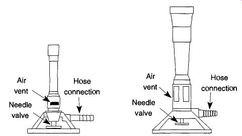
Fig. 1 Bunsen and Fisher burners.
A burner is connected to its gas source with either amber latex or vinyl tubing (Tygon). The advantage of amber latex tubing is that it has excellent memory of its original shape (See Resilience in Sec. 1.2.2). So, regardless of how long a hose is connected, the hose will always grip the hose connection it was originally slipped onto. Unfortunately, latex tubing ages over time and can easily burn. Both of these conditions, aging and burning, will eventually cause leaks in the tubing. If you use latex tubing, monitor it often for signs of age (cracking) or burns.
Never Look For Gas Leaks With a Match. Your nose will probably offer the first indication that you have a leak. Then, you can either listen for the hissing of the leak, while occasionally twisting and moving the tubing to arrange the leak region, or coat the tubing with a soapy solution and look for bubbles.
Vinyl tubing has poor memory and with time begins to conform to new shapes.
With time, vinyl tubing can lose its grip on hose connections and may leak or be pulled off easily. There are two solutions to this problem. The best solution is to use a hose clamp. This clamp will provide a secure attachment of the hose to the gas outlet and allow for (relatively) easy removal. Alternatively, you can soften the tubing by placing the end in boiling water for a minute or so. This method will allow you to shove the tubing onto the hose connection sufficiently far that the chances of accidental removal or leakage are considerably diminished.
Vinyl tubing does not age and is fire-resistant. However, a hot object may melt through the tubing causing a leak. Fortunately, because the tubing does not burn, it therefore is unlikely to ignite a combustible gas.
Removing vinyl and amber latex tubing is best done with a razor blade. Do not pull vinyl tubing off because the torque is likely to break the hose connection off.
Needle valves on both Fisher and Bunsen burners are threaded right-handed.
These valves are in reverse angles during use; that is, you observe the valves from the top. This orientation may confuse some people. Just remember that in use, you close a needle valve by rotating it CW, and open the valve by rotating it CCW.
When first setting up a burner, close the needle valve all the way. Rotate the lab bench valve to the open position (checking for leaks in the tubing at this point is advised). Light a match (or get a striker ready) and open the burner's needle valve.
Depending on the length of the tubing, you may need to wait a moment for the gas to travel to the burner (your nose is a good indicator of gas presence). Light the burner.
Once the flame has ignited, it needs to be "fine-tuned." By opening the valve you increase gas flow, and by closing the valve you decrease gas flow. By rotating the air gates on the side of the burner, you can also increase or decrease the amount of air that is allowed to premix with the gas to intensify the flame. When you open an air gate, more air is available to combine with the gas, thus producing a bluer and hotter flame. As a gate is closed, less air is available to the gas, producing a whiter ("yellower") and cooler flame.
Any flame that is predominantly white (or yellow) will smoke and deposit black (carbon) soot on any object that is placed over it. It is best to allow at least enough air in the gates to ensure a blue flame. A blue flame will not deposit soot. Additionally, a white (yellow) flame is not likely to have enough energy to accomplish any significant heating.
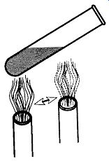
Fig. 2 Heating the whole bottom of a test tube.
The main difference between the Fisher burner and the Bunsen burner is size and heat dispersion. When trying to heat a test tube in a Fisher burner, you are likely to overheat the material. Likewise, when trying to heat a two-liter flask with a Bunsen burner, you are likely to have a long wait. The exact demarcation line of which tool you should use for which type of heating job requires common sense and experience.
If you need to heat a test tube with a Bunsen burner, follow the following rules:
1. Be sure to hold the test tube with a proper test tube holder. Do not use fingers, rags, tweezers, or pliers.
2. Hold the test tube at an angle off of vertical.
3. Do not "aim" the test tube at yourself or any other person. This positioning may be difficult in a crowded lab, but it is important. If the solution becomes superheated before boiling begins, the test tube can act like a cannon, shooting its hot contents up to 20 feet.
4. Heat along the bottom side gradually moving the test tube up and down the length of the solution (see Fig. 2).
It is preferable not to heat a beaker or Erlenmeyer flask with Fisher or Bunsen burners. The reason is discussed in detail in Sec. 1.1.10, which discuses the structural shapes of flasks. In essence, the problem is that the sharp angle of the side walls may not be able to disperse the thermal strains created by the expanding heated bottom. Round-bottom flasks, on the other hand, have no side walls and therefore do not have this problem.
There are occasions where you will need to heat materials in a beaker because no other means of heating are available. In these occasions, do not let the flame come in direct contact with the glass. Rather, place the beaker on a wire screen or on a wire screen with a ceramic square.* Even though the screen will prevent a direct concentration of heat at any one point on the beaker, use a soft blue flame, not an intense "hissy" flame.
1.4 Steam
Steam is one of the safest and easiest techniques to provide even, uniform heat in the lab. Because steam can provide an even heat distributed uniformly across the entire bottom of a container, there are no fears of hot spots or solution superheating. In addition, the steam bath is made up of simple components with no electrical wires or moving parts. Thus, there is nothing to wear out or to be damaged in a steam bath by accidental spills of heated materials.
Although steam can technically be any temperature greater than 100°C, under normal conditions the user can consider the temperature to be about 100° C. Superheated steam (>250°C) is possible, but special insulation and equipment is required.
Regardless of relative safety, caution with the use and handling of steam is still required. Careful monitoring of the equipment for the duration of the experiment or process is still important. From a safety aspect, there are two things to keep in mind about steam:
1. Distilled water cannot be hotter than 100°C (at STP), but steam can be as hot as you can get it.
2. You cannot see steam. What people often call steam is in reality the condensed water of steam that has just cooled below 100°C.
[ Some labs may still have wire screens with asbestos squares attached. These screens should be placed in plastic bags and disposed of with the proper agencies. There are replacement screens avail able that use a ceramic material and are not hazardous. As opposed to the steam source. ]
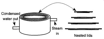
Fig. 3 The steam bath with nested lids.
These two facts point out one of the biggest dangers of steam: What you cannot see can hurt you. Caution is advised.
If you are fortunate enough to work in a facility that has self-generated steam, you can easily attach one end of a hose to the outlet and the other end to the steam bath or other steam delivery device. Be sure to use heavy-duty flexible tubing to withstand the high heat of the steam, and use as short a piece of tubing as possible so the steam will not condense before it gets to the steam pot.
Your delivery system is likely to be a steam pot (also called a steam bath) (see Fig. 3). Steam pots may be made out of copper, brass, or cast aluminum. One of the benefits of using steam for heating is that the steam bath is designed to accommodate a wide variety of flask sizes; all that is necessary is to select a nested lid that is just smaller than the size of your flask. The lid should be selected before the steam valve is opened. Otherwise the container will become too hot to handle safely, and further setup will become more difficult and dangerous. If you need to change a nested lid after it has been heated, be sure to use tweezers or tongs.
All steam pots have one tube allowing steam in and have another allowing condensed water out. Be sure that neither tube kinks or plugs up. A constricted steam tube may burst due to steam pressure. A constricted drainage tube will cause the pot to fill up with water, which will halt the progress of your work. If the tube continuously kinks, replace it with a newer and/or heavier-walled tube.
If you do not have a built-in steam line, you can create your own steam. Boiling water over an open flame, on a hot plate, or using an immersion heater are all adequate techniques.
Very elaborate steam apparatus configurations have been written up by Lane et al., for superheated steam distillations. These superheated steam setups are fairly elaborate pieces of apparatus which combine steam generation and distillation in one piece. They are therefore not setups that can be pieced together in an after noon. A more simple design of a steam generator has been proposed by Hagen and Barton.
It is a fairly inexpensive, yet robust design. Whichever steam generator design you select, it must be continuously monitored. If a steam generator runs out of water, the unit may be damaged, and the experiment or process that uses the steam will stop.
The only water you should use in an electrically heated steam generator is deionized water to decrease (and/or limit) the corrosion of internal parts caused by water electrolysis. In addition, as salt concentration goes up, current conduction increases, which may lead to power failure.
Steam units in general, and electrical steam generators in particular, should always be placed away from easy access to limit the chances of accidental burns or unintended electrical contact.
1.5 Thermal Radiation
Thermal radiation is provided by heat lamps which emit large amounts of infrared light. Besides keeping food warm at smorgasbord-type restaurants, heat lamps can be used to warm and/or dry samples.
Although heat lamps cannot provide great amounts of heat, they have the advantage of being able to work at a distance. Because heat lamps do not require contact or air to heat materials, they can be used to heat materials in a vacuum.
Do not stare at the light of a heat lamp because it can burn your retina. Similarly, do not leave your hands exposed to its light for more than a few seconds at a time because it will sunburn and damage your skin.
1.6 Transfer of Energy
By using the part of the electromagnetic spectrum between 0.1 and 10 cm, more commonly known as microwaves, energy can be transferred from waves to matter.
This is particularly effective to materials that are considered opaque to micro waves. By blocking a microwave, energy is absorbed and the material is heated.
Water and fat are both considered opaque to microwaves. Materials that are trans parent do not absorb any energy and therefore do not heat up under the effects of microwaves. Ceramic and glass materials are considered transparent and do not (appreciably) heat up under microwave bombardment. However, as in most things in life, this is not a black and white issue because nothing is totally opaque or transparent. Both glass and ceramic materials do heat up in a microwave oven, but not to the degree that materials that are considered opaque.
There have been a variety of uses of microwave ovens in the laboratory; these include the processing of ceramics, development of various plastics, catalysis, and acid dissolution of various materials.
One developing use of microwave ovens is the drying of samples for weighing.
The process of drying samples, which used to take some one to two hours in a drying oven, can be brought down to about five to ten minutes in a standard inexpensive kitchen type of microwave oven. The technique is to place the weighing bottle and cover in a clean beaker. Place three glass rods that have been bent to an angle of about 45° over the edge of the beaker to support a watch glass. The watch glass is used to ensure that nothing falls into the beaker, and the glass rods are used to allow water vapor to escape.
The exact time required for drying of samples needs to be determined for each type of microwave oven being used due to the varying power (watts) of each type.
It was demonstrated that it is possible to inadvertently melt borosilicate glass in a microwave oven
if it is kept on too long and if there is any inadvertent metal deposits on the glass. Since all glassware has potential contact with metal during its production, all glass has the potential of melting in a microwave. It is, however, an uncommon occurrence even during extended microwave heating sessions. The amount of time required to sufficiently dry a sample is considerably shorter than the time required to bring the glass to potential melting.^ The standard kitchen microwave oven has low, medium, and high settings, but these do not indicate the level of intensity of the electromagnetic beam. Rather, it creates cycle times for the beam to be on or off. Because hot areas are more opaque than cold areas, hot areas get hotter than cold areas. The level settings are used to heat areas of the material being heated, then cycle off so conduction can heat colder sections. As the oven cycles on and off, a more uniform heating can be created. It is unnecessary to use anything but the highest setting when drying samples, although when drying large samples, it may be prudent to use a lower set ting.
1.7 Hot Air Guns
Hot air guns are used to provide isolated, directed heat to individual targets. This method may be used to heat an individual sample on a vacuum line or to soften the grease on a stopcock. Although one could use a standard hair dryer, it cannot provide the control or endurance of an industrial-strength hot air gun.
There are two types of hot air guns: those that have a fan and those that do not.
The obvious advantage of those with fans is that they are self-contained. The disadvantage is that the fan motor can create sparks, which could be hazardous depending on ambient gas conditions. The disadvantages of the motorless (no fan) design: You must have access to pressurized air, and the unit must have both a power cord and air hose for operation.
Motorized air guns allow extra air to enter the side of unit through an air gate to vary the amount of extra air that can enter the air gun. The less air that can enter the side, the hotter the air exhaust. A hot air gun can produce extensive heat which can easily peel paint or crack a window pane. By concentrating the heat, from a hot air gun on a glass vacuum line, it is possible to have the glass walls be sucked in by atmospheric pressure.
[ This contamination can come from tweezers that are used to hold the glass rod while they are being bent into the required shape to the tools that are used to shape the weighing bottle. The reason the melting occurred in the first place is that the original ovens from which the drying times were determined were half as powerful as newer ovens that were later obtained. Unfortunately, power was not considered and the original drying times were used. Any small-sized stopcock that requires heat to turn should be removed, cleaned, and re-greased at the first opportunity. Large stopcocks may require a hot air gun for all rotation. Because heat ages stopcock grease faster than normal, the grease should be replaced two to three times more often than the other stopcock grease. ]
If you have pressurized air in your lab, you can use a motorless hot air gun. These units are smaller than standard hot air guns and are typically about the size of small home hair dryers. Motorless hot air guns only require heating filaments because they do not have fans. To use one, a flexible tube is attached to an air sup ply and the hot air gun. If your lab does not have plumbed-in compressed air, or the location of your outlet is too far away from where you want to use the hot air gun, another option is to use a compressed gas tank of air. Do not use compressed oxygen or any flammable gas for the air supply. You could use an inert gas, such as nitrogen for your air supply, but it would be costly.
Adjust the outgoing air pressure to between five to ten pounds of pressure. A needle valve on the regulator is required to regulate the amount of air passing the heating elements. Just like a built-in fan heater, the less air coming out of the regulator, the hotter the air out of the hot air gun, and vice versa. If the air supply runs out, you run the risk of burning the heating element. Always turn off the heating element before turning off the air supply. Otherwise, you run the risk of burning the heating element.
Probably the most common piece of worn or damaged equipment used in the laboratory is a hot air gun's electrical cord. These cords are frequently frayed due to their heavy use. Electrical cords should always be replaced as soon as there are any signs of fraying, and hot air guns deserve no exception.
1.8 Electrical Resistance Heating
One of the most versatile and robust heating techniques is the use of electrical resistance heaters. They are used in as varied heating approaches as hot plates, mantles, heat strips, immersion heaters, and even blankets.
Although some electrical heating units are self-contained with their own electrical controllers (such as hot plates), many require separate controllers. If a heating unit has no apparent built-in mechanism with which to vary temperature, the unit will require a separate controller.
[ The controller is nothing more than an electrical rheostat that can vary the amount of electrical cur rent the wires receive. This rheostat in turn also varies the amount of heat the wires can deliver. Some controllers have built-in (or external) thermocouples that enable the controller to maintain a specific temperature. ]
Some electrical heating units that require controllers will have standard electrical plugs to connect into to controllers. Despite the fact that you can, do not plug these units directly into wall outlets. Your heat demands are likely to be far less than full electrical power, and you can only receive full power from a wall socket.
Currently, more and more electrical heating units that require electrical controllers have special plugs that can only go into similarly equipped controllers. Before purchasing a heating unit, verify with the supplier or manufacturer what type of fit ting the unit is equipped with and whether it will be compatible with your existing equipment.
Some heating units such as mantles and hot plates can use magnetic stirring bars which are magnetized rods covered in Teflon. Stirring bars can provide two functions. They can stir solutions to mix different materials together and assist the uniform and efficient heating of solutions. In addition, a stirring bar creates a vortex within a solution which provides a sharp point from which boiling can occur. Thus, using a stirring bar eliminates the need for boiling chips.
Magnetic stirring bars can be stored together, but they should be placed in a clean, dry, and smooth container. The clean and dry requirements are obvious, but smooth is equally important. A rough container (or dirt in the container) is likely to scratch the Teflon. Any scratches on the Teflon may trap dirt or chemicals which may affect future work. If you think that you will be unable to otherwise maintain a dirt-free container, consider keeping the tubes that the magnetic stirring bars are shipped in for storage.
Never rotate a spinning bar too fast because it is likely to cause splashing. Like wise, place the center of a flask over the center of the controller. Otherwise the spinning bar is likely to flip around like a wounded fish, causing a lot of splashing.
Electrical Heating Tapes. These units always require separate controllers. They come in various widths and lengths and are always flexible. Depending on the insulating materials, they have upper heating temperature limits from 260°C to 760°C. Although the insulation may be resistant to chemical spills, the wires within may not. Sloppiness is therefore likely to be hazardous. Some of the insulations available should not be used against metal surfaces, so if you need to heat a stainless steel container, select suitable insulation.
Electric Heating Mantles. These mantles are like a pair of cupped hands and are designed to envelop individual round-bottom flasks. Generally, each mantle size is designed to heat one size of flask, although there are a few mantle designs that can hold a variety of flask sizes and other glassware styles. Because the mantle securely supports the flask, it cannot tip or slide out of the heater. Like steam heating, the mantle provides heat equally along the entire lower surface of a flask.
Some mantle designs provide insulation that completely covers an entire flask. This provides a uniform temperature throughout the flask preventing heat gradients within the solution and decreasing heat loss. Although the costs for separate mantles for each size flask can add up, mantles provide the best (and most uniform) heating for long periods of monitored, or unmonitored, usage.
Mantles, like electric hot plates, may have built-in controllers, some of which have thermostatic devices to set and control specific temperatures. In addition, some mantles have magnetic stirring mechanisms.
Similar to heating tapes, the insulation on mantles may be resistant to chemical spills but the wires within may not. Sloppiness is therefore potentially hazardous.
If you have a mantle with a drainage hole on the bottom, be sure to provide some sort of collection basin underneath. Otherwise, chemicals may spill onto your lab bench.
Immersion Heaters. These devices are lowered directly into a solution for heating. Because the heaters come into direct contact with their solutions, the major consideration for selecting an immersion heater is the material used to cover the heating element. Because glass is so universally resistant to (most) chemical attack, glass is commonly used. However, glass can easily be broken. In addition, glass should not be used in any alkaline, hydrofluoric acid, or hot phosphoric acid solutions as all three can dissolve glass.
The best types of immersion heater covers are made out of quartz glass. Because of quartz glass' tremendously low thermal coefficient of expansion, it is possible to remove a hot immersion heater from a solution and lay it on a cold bench top without fear of the unit cracking. Although this procedure is not safe either (some one could touch the heater and get burned), it is possible. Equally, it is possible for the immersion heater to have warmed up in the air and later be immersed into a solution without fear of cracking. This is not a safe procedure (the steam or splattered liquid could burn the holding hand), but it is possible.
Some inexpensive immersion heaters may be made from borosilicate glass.
Although they are not as capable of handling radical heat changes as quartz glass, they do quite well.
Surprisingly, as long as an immersion heater is not removed from the liquid being heated, and as long as the heated liquid is kept at moderate temperatures (20° to 30°C), even soft glass can be used as a cover for the heating element. For instance, immersion heaters for aquariums are often made from soft glass. They can survive because the water becomes a heat sink for the glass, preventing rapid heat changes that would otherwise cause it to crack or from getting too hot and failing.
Immersion heaters with metal covers are more robust against physical abuse, and typically copper and stainless steel are used. Copper covers may be capable of some flexibility and can allow for adaptation to specific confined areas; however, they are more susceptible to chemical attack.
Hot Plates. These devices have a metal (cast aluminum, stainless steel, or some alloy), ceramic, or pyroceramic top. Underneath the top is an electric resistance heater. Hot plates are used for heating flat-bottom containers such as beakers and Erlenmeyer flasks. Because hot plate tops are non-porous, there are fewer concerns for spills affecting the heating elements as there are with heating mantles. Magnetic stirring devices are commonly included with hot plates.
Pyroceramic and ceramic tops are impervious to most chemical spills. The exceptions are typically any of the chemicals that can attack glass, such as hydrofluoric acid, alkali solutions, and hot phosphoric acid. Metal-topped hot plates can take more physical abuse than ceramic or pyroceramic tops. In addition, with metal, there are no concerns about scratches or cracks that, on a pyroceramic top, could lead to further deterioration. Metal-topped hot plates are, however, subject to corrosion from chemical spills.
[Pyroceramic is a translucent material made by Corning that has both glass and ceramic properties.]
Never place a cold beaker or Erlenmeyer on a heated hot plate, and likewise never take a hot beaker or Erlenmeyer and place it on a cold bench as either could cause the bottom of the container to break by thermal shock. One way to reduce the amount of thermal shock when transferring a container on or off the hot plate is to place it on something with less heat capacity, such as a wire screen.
Hot plates are also used to heat one type of material so that a second may be heated. These secondary heaters may include water baths, oil baths, sand traps, or aluminum plates. Water and oil baths are typically used to heat a drying flask on vacuum evaporators. Oil baths are more messy and require special clean up, but the oil (typically a silicone oil) will not evaporate during drying processes that can take up to several hours. Stronski came up with a very simple and easy solution to limit water evaporation. Stronski recommended that the user float Styrofoam popcorn or chips up to three inches deep on water. This suggestion not only limited evaporation, but extended the maximum controlled temperature range.
The advent of various brands of microware laboratory equipment (originally developed by Mayo, Pike, and Butcher of Bowdoin College ) created a problem of how to heat these new, smaller flasks. Two techniques have developed. The first involves placing the microflasks into sand. The advantage of sand is that it can easily fill into all the external nooks and crannies of any container and provide excellent, evenly distributed heat. The disadvantage of sand is that it is a poor heat conductor and can thus require a long time to be heated to a satisfactory tempera ture. In addition, once you remove a flask, it is not easy to reinsert a new flask into the "filled-in" hole.
An alternative approach is a solid aluminum block. This idea was developed jointly by Siegfried Lodwig of Centralla College and Steve Ware of Chemglass, Inc. Aluminum conducts heat excellently and can be easily machined to accommodate different sized flasks. The success of aluminum heat blocks caused Lodwig to use them also for a variety of other heating techniques that had nothing to do with microware.
Because a variety of individual holes may be drilled into a single aluminum block, it is possible to easily rotate different-sized flasks on a random basis with ease and have separate holes for thermometers as well. The thermometer allows you to easily monitor temperatures for various thermostat settings. By graphing these temperatures settings, one can easily set a temperature on a Variac as easily as setting a temperature on a stove.
Drying Ovens. These units are used to facilitate the drying and storage of glass ware that needs to be dry and ready at a moment's notice. Drying ovens are also used to dry samples for weighing.
Glassware should never be wiped dry because the wiping process could easily contaminate the surfaces. There is no reason to dry glassware that will be getting wet immediately after washing. Similarly, there is no reason to place items in a drying oven that could otherwise drip dry. Glass typically has a certain amount of adsorbed water at all times. The only way to reduce this water is with heat and/or vacuum. The drying oven provides limited assistance for the former and will not only help to remove some of this water, but if the container is left in the oven, will help keep the water from returning as long as the glassware remains in the oven.
The last rinse before placing glassware into a drying oven should be with distilled or deionized water. Regular tap water may leave remains (seen as spots) that will contaminate the glassware. If possible, rotate the glassware so that liquid can drain during the drying process. Although it is acceptable to use technical grade acetone or methanol for a final rinse when not using a drying oven, never use either of them in conjunction with a drying oven. Flames or even an explosion can result from such a combination.
Drying ovens are typically set at 120°-130°C, which is well below the recommended temperature of about 400°C needed to remove all adsorbed water. Contrary to misconception, it is completely safe to place any borosilicate volumetric ware in a drying oven. The temperature is way below what is needed to cause any distortion and resultant volume changes. Objects placed in drying ovens should remain three to four hours, so that the drying of the glass (the adsorbed water) can reach an equilibrium. Otherwise, if items look dry, they probably are dry.
Never place plastic items into a drying oven, especially items made of Teflon.
Typically, there is enough heat leaking through the top of a drying oven for plastic items to be placed on the top for drying. To prevent the plastic items from scratches or contamination, place them into an Erlenmeyer flask or beaker. When assembling Teflon stopcocks where the barrel was just removed from a drying oven, wait until the item is completely at room temperature before final assembly.
A Teflon stopcock that is snug when warm is likely to leak when cooled to room temperature.
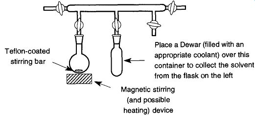
Fig. 4 A static vacuum can be used to remove solvents from samples.
1.9 Alternatives to Heat
Heat is typically used to bring a solution to its vapor point (boiling) so that it may be distilled, reduced, or purified. Although this procedure works in most cases, not all solutions can be safely heated. Some materials break down in heated conditions, and some do so violently. Fortunately, there are two alternative methods to obtain the vapor pressure of a material; one is to raise the heat, the other is to lower the pressure. By using a vacuum (see Section 7) to obtain the vapor pres sure of a solvent, the solvent will boil off, leaving the material behind. This procedure can be done at room temperature or slightly above room temperature.
The catch to the vacuum method is that you must have a controlled boil without which the material and/or solvent are liable to be sprayed all over your vacuum system. Although a solvent can easily be pumped out of a vacuum system, it can cause serious problems if it remains in contact with stopcock grease, O-rings, or mechanical and/or diffusion pump oils. Any particulate material deposited within a vacuum line can only be removed from the vacuum line by disassembly and cleaning. With a glass vacuum system, such a cleaning may be difficult or impossible.
The standard approach to maintaining a controlled boil is to use boiling chips as one uses when boiling materials over a Bunsen burner. However, these chips have limitations because they may be very difficult (or impractical) to remove at a later time.
One of the best approaches for maintaining a controlled boil is to place a Teflon coated stirring bar in a flask and then place the flask over a magnetic stirring device (as mentioned in Sec. 6.1.8). In a medium- to high-vacuum system (10^3 to 10^ 5 torr), this activity can be done in a static vacuum with a container sitting in liquid nitrogen (or a slush bath; see Sec. 6.2.7) near the material in question (see Fig. 4). The liquid nitrogen acts as a cryopump, thereby trapping all the solvent boiling off and maintaining a constant pressure and, therefore, a constant boil. If your using liquid nitrogen, do not pour it around the trap until after the vacuum line has been evacuated to prevent trapping of oxygen, otherwise the system may later blow up due to expanding gases.
2. Low Temperature
2.1 The Dynamics of Cold in the Lab
Cold can be used in the laboratory to prevent an experiment from getting too warm, to slow the rate of a reaction, to transfer materials in a vacuum system, to allow for the separation of materials (with fractional condensation), to decrease the vapor pressure of materials so as to trap them in vacuum systems, or as a (cryogenic) vacuum pump.
The physical mechanisms of cold transfer are the same as heat transfer and use the same physical processes of conduction, convection, and radiation/absorption (for more information on these processes see Sec. 1.1).
Both hot and cold express different degrees of thermal energy and are directly related to each other. The decision of what is hot or cold is a subjective choice.
Heat (energy) always transfers to cold (lack of energy). So, whichever object is relatively hotter will transfer some of its thermal energy to the object that is relatively colder. Thus, the water running through a condenser does not cool the con denser. Rather, the condenser loses some of its heat to the water, which in turn leaves the condenser (by way of tubing) and is replaced by water, ready to be heated. As the heated water is removed, it takes that amount of heat energy away from the condenser. Although this distinction may seem inconsequential, it is fundamental to the understanding of what is taking place in the cooling process.
Cooling could also be considered a "removing heat" process.
To cool materials in the lab, you need to select cooling materials that are sufficiently cold and have the heat capacity to remove the necessary thermal energy.
The following subsections describe techniques used to make things cold in the laboratory.
2.2 Room Temperature Tap Water (=20°C)
Water is used as a coolant in condensers and diffusion pumps. For simple exothermic reactions, you can use water as a heat sink by placing glassware (containing a reaction) into a water bath. Alternatively, in an exothermic reaction, you can also use a cold finger of running water to prevent overheating. However, all these examples can only cool to the temperature of tap water (usually room tempera ture). For every step below room temperature, more equipment and money are required.
2.3 Ice (0 C)
Many labs have freezers or ice machines to make ice.* [* If you constantly lose the scoop in the ice, tie one end of a string or cord on the scoop and tie the other end on the ice machine.]
If the ice is in cubes or blocks, it will be necessary to smash it into more usable, smaller, crushed pieces.
The ice should be placed in some kind of cloth bag (or the like) during smashing, to prevent the ice pieces from flying around the room. Be sure to wear safety glasses any time you are smashing anything-and watch the fingers!
2.4 Ice with Salts (0 C to -96.3 C)
Various salts can cause freezing point depressions. These depressions are the results of the ions' colligative properties within solution. A significant freezing point depression is created not by any particular type of material, but rather by the number of particles you have in solution. The effects can be enhanced by achieving a supersaturation of material. For example, if you mix ice with a salt such as NaCl, you will end up with two particles within solution (Na + + Cl") (the tempera ture of ice water supersaturated with sodium chloride (23% by weight) is - 20.67°C). If you place a salt such as CaCl2- H2O into ice, you will end up with three particles within the solution (Ca + + 2C1~) [the temperature of ice water supersaturated with calcium chloride (30% by weight) is -41.0°C]. Furthermore, because you can get more methanol saturated into the ice water (68% by weight), you can achieve a greater freezing point suppression (-96.3°C). To a certain degree, you are limited by the solubility of a compound. Materials such as Ca(NO3)2 and H2SO4 have unlimited solubility. However, because of the corrosive nature of H2SO4 it is not a good choice for general use. Table 6-1 lists a wide variety of salts and compounds and their freezing point depressions by percentages of weight.
2.5 Dry Ice (Frozen Carbon Dioxide) (-78 C)
Dry ice comes in blocks that are wrapped in paper and are kept in specially insulated ice boxes. Because there is no liquid stage of CO2 at STP, there is no fear of liquid leaking out of these paper containers (the triple point* of dry ice is at 5.2 atm and -57°C). Never handle dry ice with your bare hands. At 1 atm, dry ice sublimes at -78°C. At these temperatures, severe tissue damage could result. You should always use heavy thermal gloves or tongs.
Dry ice, like water ice, can be smashed into smaller, more practical pieces. Like regular ice, it should be placed in a cloth bag for smashing to prevent ice chips from flying around the room.
2.6 Liquid Nitrogen (-195.8 C)
Liquid nitrogen is deceptively dangerous; it looks like water, but at its extremely cold temperature (-195.8°C), liquid nitrogen can do extensive tissue damage. A common lab demonstration is to place a flower into a Dewar of liquid nitrogen, remove the flower, and hit, or crush, the flower with a blunt object. The previously soft flower shatters as if made of fine glass. A finger can shatter just as easily.
Liquid nitrogen is shipped and stored in large insulated liquid/gas tanks (see Sec. 2.10). To dispense liquid nitrogen out of the large insulated storage tank, connect a metal tube to the "liquid" valve on the tank. Then place a receiving vessel over the end of the tube, and open the liquid port valve until the desired amount is obtained (see Fig. 8).
Liquid nitrogen should only be transported and held in double-walled, insulated containers. Transport containers should have narrow necks to avoid spillage (see Fig. 9).
[The triple point of a compound is when the atmospheric pressure and temperature are compatible for the solid, liquid, and gas forms to exist in equilibrium at the same time.]
Never leave liquid nitrogen in noninsulated containers (i.e., beakers). In a noninsulated container, liquid nitrogen will boil away very fast and thereby require constant replacement (an economic loss). In addition, any water condensation will cause the container to freeze onto its resting surface, making it difficult to move without breaking the beaker and increasing the potential danger. Finally, the most important reason to never place liquid nitrogen in a noninsulated container is that someone may inadvertently try to pick up the container and severely burn his or her hands.
2.7 Slush Baths (+13° to -160 C)
A slush bath can be described as a low-melting-point liquid (typically a hydrocarbon solvent) that is being kept in a partially frozen state by either liquid nitrogen or dry ice. The temperature will remain constant as long as you continue to add liquid nitrogen, or dry ice, to the bath to maintain its "slushy" state. Table 6-3 is a comprehensive list of slush baths made of dry ice (CO2) and liquid nitrogen (N2). Duplicate temperatures indicate a choice of solvent or coolant.
To make a slush bath, pour the selected low-melting temperature liquid into a Dewar, then pour the coolant in while stirring briskly. A wooden dowel is wonderful for stirring because it will not scratch the Dewar's surface. There is no concern for contamination from the dowel because it is not likely to affect the performance of the slush bath.
During the mixing process, tremendous amounts of solvent fumes are likely to be given off along with condensed water from the air. Therefore, the original preparation of a slush bath should be done in a fume hood. Once the slush bath begins to reach equilibrium, the amount of vapors leaving the Dewar decreases and it is safe to remove the bath from the fume hood.
To make a liquid nitrogen slush bath, first pour the desired low-melting temperature liquid into a Dewar. Then slowly, while constantly stirring, add the liquid nitrogen until the desired consistency is achieved. Different low-melting liquids will have different viscosities. It is therefore desirable to know the potential viscosity limits of the slush bath you are using. This information is best retained by asking someone; otherwise, make a test slush bath before you set yourself up for an actual experiment or process. Knowing the viscosity of a certain slush bath is important, otherwise you may expect one slush bath to be as thick as another, and you might add an excess of liquid nitrogen. If you add too much liquid nitrogen, it will become the predominant cooling medium and the resultant temperature will be cooler than listed in Table 6.3. However, as the liquid nitrogen boils off, the temperature will settle to the listed temperature.
To make a dry ice slush bath, be sure that your low-melting-temperature liquid has a freezing point above -78°C. Follow the same procedure as with the liquid nitrogen bath above, but use crushed dry ice. When crushing dry ice, use a hammer (not a pair of pliers or a wrench) and place the dry ice in a cloth bag so the pieces do not fly around the room. Always handle dry ice with thermal gloves or tongs, and never handle dry ice with your bare hands or you might severely burn your hands and fingers. The primary advantage of using dry ice over liquid nitro gen is that it is less expensive, safer to work with, and more readily available. On the other hand, it is more difficult to work with. Similar to liquid nitrogen, if you add too much dry ice, it becomes the predominant cooling medium and the result- ant temperature will be cooler than listed in Table 3. As the dry ice evaporates, the temperature will settle to the listed temperature.
By combining mixtures of organic solvents, it is possible to achieve temperatures that you may not otherwise be able to obtain because of lack of material or to avoid other materials. For example, with various combinations of ortho- and meta-xylene and dry ice, you can achieve temperatures from -29°C to -72°C (see Table 1).
Regardless of which coolants or low-melting-point liquids are used to make a slush bath, no slush bath combination can be a perpetual (static) temperature sys tem. Rather, a slush bath is a dynamic collection of materials that are either settling or boiling off. Thus, they require constant monitoring with (preferably) two liquid-in-glass thermometers (or a thermocouple probe), consistent agitation, and occasional replenishing of coolant.
An alternative to the slush bath is the coolant, or cooling bath. These baths are handy when you may not have (or wish to use) the required low-melting-tempera ture liquid for a particular temperature. However, they require more work to maintain their specific temperatures. Liquid nitrogen is recommended for cooling baths because dry ice can be difficult to introduce to the bath in sufficiently small amounts. Like the slush bath, the cooling bath should be mixed in a fume hood.
The cooling bath differs from the slush bath because less coolant is used during initial mixing. Thus, the mixture never obtains the slushy state of the slush bath.
The resultant bath temperature is warmer than the coolant, and by varying the amount of coolant you can vary the temperature. The trick is to select a low-melting-point liquid that is sufficiently low to provide a wide working temperature range. One good cooling bath liquid is methanol, which has a freezing tempera ture of -98°C, is reasonably safe to use, and can easily be used for cooling baths.
Another reasonably safe, low- melting-point liquid is petroleum ether (30°-60°) which has a freezing point of approximately -120°C, and can thereby provide a greater range of low temperatures.
The difficulty involved with cooling baths is that you control the temperature by varying the amount of coolant in the mix. This control requires constant attention and the slow but constant addition of more coolant as the bath continues to warm during use. Despite the extra labor, many people prefer cooling baths because there is a greater choice of safe solvents. In addition, fewer solvents must be stored to obtain a wide range of temperatures.
[By using two liquid-in-glass thermometers, you can verify the quality of both thermometers by their agreement in temperature readings. If the temperatures do not agree, one of the thermometers may have a bubble in the stem or some other defect. Unfortunately, this trick does not let you know which is the defective one, but it provides a clue to the problem. Methanol is flammable and poisonous.]
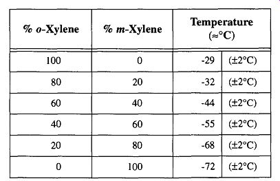
Table 1 Temperature Variations with Combined Organic Solvents
2.8 Safety with Slush Baths
Because the low- melting-point liquid in the slush bath is near its freezing temperature, there is little concern over toxic fumes as when working with some chemicals at room temperature. However, in the beginning, you must work in a fume hood because of the copious amounts of fumes released from the low- melting point liquid. Once the slush bath is made, it is safe to remove it to the lab. How ever, it is best to leave the slush bath in the fume hood if at all possible. If the slush bath is used in the lab, move the slush bath to the fume hood immediately after your work is completed.
Never pour a slush bath down the sink. The low temperatures can destroy plumbing! Instead, let the coolant boil off in a Dewar in the fume hood. Later, the low-melting-point liquid can be saved and reused.
Because slush baths achieve very low temperatures, protect your hands from the extreme cold. This protection presents some problems with the current tempera ture-protecting gloves available and problems inherent with slush baths. Thermal gloves made out of Kevlar, a plastic, can be dissolved by some organic solvents.
Thermal gloves made out of fiberglass are okay, but they are very slippery. In addition, broken glass fibers from fiberglass gloves can get under the skin and itch for many days. Asbestos gloves are not allowed in most states. My personal choice among all these suggestions would be the Kevlar gloves and don't be sloppy.
[ Kevlar gloves are banana yellow with a surface like terry cloth. If your laboratory still has some asbestos gloves, you may need to check with your safety officer or the Department of Health in your area for proper disposal. ]

Table 2 Freezing Point Depressions of Aqueous Solutions
Incidentally, when making slush baths out of organic solvents, do not use utensils (such as stirrers) that will dissolve in the organic solvent you are using.
Although a thermometer may already be in the container and ready to stir with, do not use it as your stirrer because it may break from the torsional forces of stirring the thick slush. Wooden dowels are excellent for mixing because they are strong and will not scratch the surface of a Dewar. You can always hold a thermometer and wooden dowel together and stir as a single device.
A potentially explosive situation can develop when an acetone slush bath is left sitting for an extended period. Over time, the acetone and dry ice separate and the acetone floats to the surface, whereas the dry ice settles to the bottom of the Dewar. The acetone soon warms up to near room temperature, but the dry ice remains near the slush bath temperature of -77 °C. If any agitation causes the warmed acetone to cut into the dry ice slush on the bottom, a flume of boiled off CO2 can erupt. This flume will carry the acetone layer that was on the surface in a large spray all around the area. If there is a flame or spark (from a motor) in the path of the acetone, this accident could have far greater consequences. This situation can be easily avoided by constantly mixing the solution. A safe alternative to the acetone slush bath is the ethanol slush bath. The ethanol slush bath is some what warmer (-72°C) but does not display the same potentially dangerous capabilities.
2.9 Containment of Cold Materials
There are two concerns for the storage of cold materials: longevity of the material and safety to the user. For example, if you place an ice cube on a lab bench, it will melt. On the other hand, if you place an ice cube in an insulated container, it will also melt-but it will take longer. By providing insulation, you have added to the ice cube's longevity. If you hold an ice cube for an extended time, your hands will soon become so cold that eventually you will need to drop the ice cube. However, if you hold an insulated container containing an ice cube, there is no discomfort.
The reason for stating the obvious is to establish the purpose of specialized containers for containing cryogenic solutions. A properly made container protects the materials inside the container and also protects the users outside. In addition, the container should be able to reasonably deal with the expected physical abuses that may be encountered within the lab. The final selection of a cryogenic container is based on its shape, design, construction material, use, and function. Although it is possible to use a Styrofoam cup to contain cryogenic materials such as liquid nitrogen, it is a poor choice for the demands of a laboratory. On the other hand, placing tap water in a Dewar may be a waste of money. As with most decisions in the lab, common sense must be used when making equipment selections. Ultimately, the selection of the quality, shape, and design of a coolant container may be based on six criteria:
1. Cost of coolant. If the coolant is inexpensive and readily available, you don't need a highly efficient container.
2. The coldness of the coolant. The greater the temperature difference of the coolant from the ambient room temperature, the better the quality of insulation required.
3. Use of the container. Will the container be stationary most of the time with little contact? Will the container be used indoors or out?
4. The handling abilities of the user. Is the user clumsy or careful?
5. The operational use of the coolant. Will the coolant need to be left unattended for long periods of time?
6. The cost of the container. A 1-liter beaker costs = $5.00 at list prices. A 1-liter glass Dewar costs ~ $45.00. A 1-liter stainless steel Dewar costs = $95.00.
Dewars. Dewars are the best and most commonly used cryogenic containers in the laboratory. Their ability to maintain a temperature is exceptional. They are used in most labs where dry ice is found and in all labs where liquid nitrogen is found. Dewars are also found in many lunch boxes as Thermos bottles. Dewars are typically identifiable as a hollow-wall glass container with a mirror-like finish.
That "mirror" finish is a very accurate description because the silver coating on Dewars is the same as is used on mirrors.
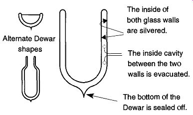
Fig. 5 A cross section of the Dewar and alternate Dewar designs.
As can be seen in Fig. 5, the Dewar is a double-wall glass container which is coated on the inside with a silver deposit. During manufacturing, after the Dewar is silvered, it is attached to a vacuum system and evacuated to about 10^-6 torr before being "tipped off" to maintain the vacuum on the inside. The Dewar achieves its temperature maintenance capabilities because of three different principles:
1. Glass is a poor conductor of heat, meaning that there will be very little temperature exchange from the coolant inside the Dewar with the rest of the container not in contact with the coolant.
2. The vacuum (within the double walls of the Dewar) cannot conduct heat.
3. Because temperature cannot cross this "vacuum barrier," the cooling is further contained within the Dewar.
The silvered coating on the inside of the Dewar reflects radiation. The silvered coating prevents heat loss/exchange with the outside world. For all of these features to be available in one package is an impressive feat. However, because glass can break under rugged conditions, it sometimes is preferable to use Dewars that are made out of stainless steel. Although stainless steel Dewars do not have all three of the heat exchange barriers of glass (stainless steel is not a good conductor of heat, but it conducts heat better than glass), they can stand up to far more physical abuse.
Table 3 Slush Bath Temperatures
Glass Dewars should always be wrapped with fibered tape (not masking tape) to prevent glass from flying around in the event that the Dewar is accidentally bro ken. Some commercial Dewars have a plastic mesh. This mesh is acceptable, but wrapping with tape provides much better support to prevent flying glass. In addition, wrapping with white tape (such as any sport tape) provides one extra level of insulation for the Dewar than if the Dewar was wrapped with black tape. Dewars come in a variety of shapes and sizes as can be seen in Fig. 5.
If frost appears on the outside of a Dewar, the vacuum within has deteriorated and the Dewar is no longer usable. This deterioration is typically caused by an imperfect tip-off at the base of the Dewar. It may take months or years for a Dewar to lose its vacuum; but once the vacuum is gone, the Dewar cannot effectively hold cryogenic fluids. It is possible, however, for a glass shop to open the Dewar, clean, re-silver, re-evacuate, and re-tip-off.
Foam-Insulated Containers. Foam-insulated containers are an inexpensive alternative to Dewars. They are double-walled (hollow-walled containers that are filled with an insulating foam instead of a vacuum. These containers (which come in as many shapes and sizes as regular Dewars) are significantly less expensive but much less efficient than standard Dewars.
Foam-insulated containers are adequate for some slush baths, but will require more effort to maintain the coolant. Foam-insulated containers should never be used for long- or short-term storage of cryogenic liquids. They may be used for cryogenic liquid transport, but there will be significantly more loss of the liquid coolant (even in limited transport) than from a regular Dewar.
Beakers and Flasks. Beakers and flasks are the least effective containers for cryogenic materials because there is no insulation whatsoever. However, if the coolant is only water, ice, or a salt/ice mixture, not much insulation is required.
There is little concern for rapid material loss with these coolant solutions because they are easy and inexpensive to replace. In addition, it is (usually) safe to pick up these containers with your bare hands. If any ice forms on the sides of a container, it is simple to use gloves or tongs to pick up the beaker or flask and prevent possible skin damage.
2.10 Liquid (Cryogenic) Gas Tanks
Nitrogen, argon, and oxygen can be stored in liquid form in cryogenic gas tanks. As can be seen at the left of Fig. 6, they are large containers (about four and one-half feet tall and 20 inches in diameter). These tanks are in fact highly rein forced double-walled Dewars and can maintain the various cryogenic gases in liquid states (at room temperature) with a minimum of bleed-off.
Liquid nitrogen is used almost exclusively as a coolant in the lab. Liquid argon and oxygen are not used as coolants, but they may be used in the lab or in industry when large quantities of these gases are required. The liquid form of the gas occupies much less space than the equivalent quantity of compressed gas. In addition, less time is lost in changing the equivalent number of tanks that would otherwise be required.
There are two major types of cryogenic tanks: one used primarily for liquid dispensing (see Fig. 6 and Fig. 7) and another used primarily for gas dispensing (see Fig. 6 and Fig. 10). Both are similar in size, both have rings of sheet metal around their tops to protect their valves from impact, and both have float devices on the top that indicate approximate liquid volume.
Both of the cryogenic tank designs have a tare (net) weight of =230-250 lb, depending on design and manufacturer. When filled with a gas, the tank's weight is considerably greater: With nitrogen its weight is >300 lb, with oxygen its weight is >400 lb, and with argon its weight is >500 lb.
Unless you have the proper training and equipment, never attempt to move a cryogenic gas tank by yourself. Should one of these tanks be tipped over and rupture, the potential dam ages and injuries could be extensive.
The Liquid Dispensing Tank. As opposed to high-pressure tanks filled with a highly compressed gas, cryogenic gas tanks hold the liquid form of a gas and are insulated to maintain the cryogenic temperatures necessary to maintain the gas in its liquid state.
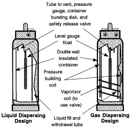
Fig. 6 The internal designs of liquid and liquid/gas dispersing cryogenic
tanks.
From Instruction Manual PLC-180A and PLC-180LP, Figs. 3 and 8, by MVE, Bloomington, MN 55425, reproduced with permission.
Although the liquid dispensing tank can provide gas, it is best suited for dispensing liquids. The tank develops a head pressure of 20 to 30 psig, which is sufficient to dispense the liquid gas (like a seltzer bottle) at a reasonable flow rate. If you remove the gas (as opposed to the liquid) at too fast a rate, the head pressure drops sufficiently that the amount of discharge equals the rate of gas creation, and the pressure drops to zero.
As seen in Fig. 7, the liquid dispensing tank has a gas port, liquid port, and a third port with a pressure gauge. Normal pressures are around 20 to 30 lb/in.^2.
This pressure will change as liquid is dispensed or as the temperature conditions of the room change. Attached to the pressure gauge is a pressure release valve to prevent excess pressure buildup. Above a predetermined pressure, any excess pressure would pass out through the release valve with a loud, hissing sound. If this release occurs, do not become alarmed, because the safety valve is simply doing its job.
[The "head" is the gas space within the container, above the liquid.]
Each port on a cryogenic tank should have a small, metal tag identifying each valve as gas or liquid. Unfortunately, these tags are often broken off, leaving you with little idea of which port is which. Figure 6.7 shows one configuration that can be used for reference. However, not all manufacturers follow this pattern. If the tags are broken off, you have three ways of finding out which of the two ports will deliver gas or liquid, respectively;
1. Call the supplier of the tanks and ask which valve delivers gas and which delivers liquid.
2. See if there are any tanks elsewhere in your building of that type and/or design. Because it is likely that any tanks from the same supplier will be of the same type, it is a safe guess that the valve setup will be similar.
3. Open and close the valve quickly several times to see what comes out.
Be sure that the area in front of the valve is free from materials that could be damaged by cryogenic temperatures. The first thing out of the liquid port will most likely be gas because it may take a moment or two for the liquid to arrive. Be sure you have adequate ventilation before doing this activity. Nitrogen and argon can displace air, leaving the user in an oxygen-poor environment. Do not use this technique with oxygen if there are any flames or sparks in the area.
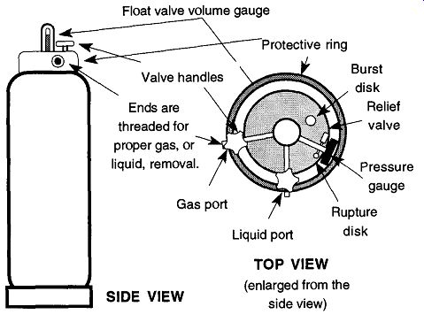
Fig. 7--The liquid (cryogenic) gas tank for liquid dispensing.
The port in the middle (which may have a small metal clip hanging from it saying "Liquid") dispenses the liquid form of the gas within. To dispense the liquid into a Dewar, first attach a dispensing tube, which is available from your gas sup plier. Place the opening of your Dewar over the end of the tube, and then slowly open the valve (see Fig. 8). Hissing and gurgling indicate that the liquid gas is pouring out the end of the tube. Always point the open end of the Dewar away from your face and other people when filling so that any splattering cryogenic liquid will not fly into your face. You should wear safety glasses during this and any other operations with cryogenic fluids. Some labs may have a separate room where liquid nitrogen tanks are stored.
[Important: If you have such a room, be sure to leave the door open whenever transferring nitrogen into Dewars. The expansion of the nitrogen can easily leave a closed room oxygen-poor!] This tank setup might service one lab, a whole floor, or an entire building. To transport liquid nitrogen from a storage container to a lab and provide short-term (one day) storage for the lab, there are various designs of transport Dewars (see Fig. 9). Transport Dewars are made of stainless steel, cop per, plastic, or fiberglass. They are double-walled containers that are evacuated or foam-filled for insulation. The necks of transport Dewars should always be small compared to the size of their bodies. This design helps prevent splashing while transporting and facilitates pouring cryogenic fluids. When used for storage, a Styrofoam ball and pin should be loosely* placed in the neck to limit evaporation.
It is essentially impossible to fill a short or shallow container from a liquid/gas tank because the liquid gas leaves the dispensing tube forcefully (there is limited ability to control the rate of flow), and once the liquid gas hits the bottom of the relatively warm container, it immediately (and forcefully) boils off and out of the container. In a taller container, the liquid gas does not eject itself from the container, but falls back to the bottom. Once back at the bottom, it can cool the container so that newly arriving liquid gas will not boil off. Eventually, incoming liquid gas will collect in a taller Dewar. A short or shallow Dewar can then be filled from the taller Dewar because the liquid can be slowly poured, limiting the amount of resultant ejecting fluids.
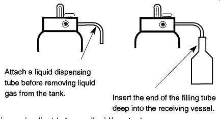
Fig. 8 Dispensing liquids from a liquid/gas tank.
[If the cap is too snug, the expanding pressure (of the gas evaporating) may cause the cap to be ejected like a rocket or cause the container to explode.]
The Gas Dispensing Tank. The gas dispensing tank (the body is shown in Fig. 6, the top is shown in Fig. 10) is designed to provide gas continuously at a delivery pressure between 75 to 175 psig. It can provide a continuous supply of 250-350 cfh (cubic feet per hour) with bursts of up to 1000 cfh. These tanks can dispense liquid as well, but it is necessary to alter them by replacing the pressure relief valve from the supplied 235 psig valve to one of 22 psig. However, once the alteration is done, the tank cannot dispense gas at the greater pressure unless the tank is restored to its original condition.
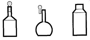
Fig. 9 Various designs of cryogenic liquid transport containers.
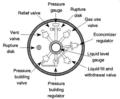
Fig. 10 Top view of pressure building liquid/gas tank. From Instruction
Manual forPLC-180A and PLC-180LP, Fig. 5 from MVE, Bloomington MN, 55425.
Reproduced with permission.
The pressure building valve is connected to a series of heat transfer tubes within the casing that encircles the inner portions of the tank. By opening this valve, a much higher gas pressure can be achieved (while releasing the gas) than could otherwise be maintained. Oxygen and nitrogen tanks are set to deliver 125 psig, and argon tanks are set to deliver 75 psig. All gas dispensing tanks can be attached to an external vaporizer to provide gas at higher rates and/or pressures than may otherwise be available solely through the internal vaporizer.
An external regulator must be attached to a gas dispensing tank (just as you would to a high compression tank) to control the gas (tank) pressure to the desired (outflow) pressure. Liquid cryogenic tanks follow the same CGA (Compressed Gas Association) numbering standards (see Sec. 5.1.3) as compressed gases. For oxygen, use a CGA 540 fitting, and for nitrogen or argon, a CGA 580 is required.
To use a gas dispensing cryogenic tank, attach the correct regulator to the gas use outlet. Then, open the gas use valve and pressure building valve. Once the pressure is at least 125 psig, you may then adjust the regulator to the required delivery pressure and dispense the gas as needed. Do not handle any tubing from the tank without some protection because it will be very cold and can severely damage skin.
Cryogenic tanks have limitations that become immediately obvious if gas is withdrawn at a rate faster than the internal coils can maintain: Frost develops on the outlet connections and/or regulator, which decreases gas output. The problem can be resolved with an external heat exchanger. The external heat exchanger is first connected to the gas use valve, and then the regulator is attached to the external heat exchanger.
Other options for gas dispensing cryogenic tanks are manifolds that can connect two to six cylinders together. These manifolds can provide flow rates of 250 cfh (cubic feet per hour), can set up a reserve of gas for uninterrupted flow when changing cylinders, and (with an economizer circuit) can cut loss due to evaporation. For extra-high-capacity gas demands, there are external vaporizing manifolds, which are a combination of the external heat exchanger and manifold n setup.
References
1. R.K. Lane, P.D. Provence, M.W. Adkins, and E.J. Elsenbraun, "Laboratory Steam Distillation Using Electrically Generated Superheated Steam," Journal of Chemical Education, 64, pp. 373-375 (1987).
2. J.P. Hagen and K.L. Barton, "An Inexpensive Laboratory Steam Generator," Journal of Chemical Education, 67, p. 448 (1990).
3. R.Q. Thompson and M. Ghadiali, "Microwave Drying of Precipitates for Gravimetric Analysis," Journal of Chemical Education, 70, pp. 170-171 (1993).
4. D.R. Beltran, E.P. Hervey, and H. Keyser, "Teaching with the Commercial Micro wave Oven," J. of Science Teaching, 9, pp. 91-92 (1979).
5. H. Keyser, "Some Uses for the Commercial Microwave Oven in Chemistry," Chemistry, in Australia, 45, p. 44, (1978).
6. A.B. Brown and H. Keyser, "Sample Preparation for Strontium Analysis of Ancient Skeletal Remains," Contributions to Geology, University of Wyoming, 16, pp. 85-87(1978).
7. G.S. Coyne and R. Keys, "The Unintended Melting of Glass in a Microwave Oven," Proceedings of the Forty First Symposium on the Art of Scientific Glassblowing, pp. 84-92, 1996.
8. R.E. Stronski, "Minimizing Evaporation from Constant Temperature Water Baths," Journal of Chemical Education, 44, p. 767 (1967).
9. D.W. Mayo, R.M. Pike, and S.S. Butcher, Microscale Organic Laboratory, John Wiley & Sons, New York, 1986.
10. S. N. Lodwig, "The Use of Solid Aluminum Heat Transfer Devices in Organic Chemistry Laboratory Instruction and Research," Journal of Chemical Education, 66, pp. 77-84 (1989).
11. Frank Dehann, personal conversation.
12. Instruction manual for PLC-180A & PLC-180LP, from Cryogenic Services Inc., Canton, GA 30114.
13. Instruction manual for PGS-45 Portable Gas Supply System, Form 13-109-D (February 1975), from Union Carbide Cryogenic Equipment, Indianapolis, IN 46224.