AMAZON multi-meters discounts AMAZON oscilloscope discounts
(cont. from part 1b)
4. Traps
4.1 The Purpose and Functions of Traps
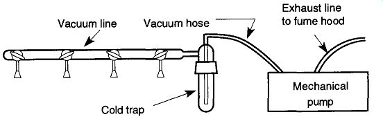
Fig. 29 A cold trap is worth the trouble on even a simple vacuum system.
Traps (and baffles and filters) are used on vacuum systems because of the need to remove, catch, or bind condensable vapors, paniculate matter, and aerosols. To obtain a vacuum, you must remove everything from a given area. However, like the environmental adage "you cannot throw anything away," you may not want everything that is removed from a vacuum system passed into the pumping system, or into the air you breath. Solvents (and their vapors) can impair or severely damage mechanical pumps by dissolving seals or by breaking down mechanical pump oils. Paniculate matter passing into a mechanical pump can severely dam age veins and seals. Condensed vapors in pump oil can impair a pump's performance. Volatile compounds that pass through a pump and leave as aerosols can expose technicians to an unacceptable health risk. Thus, the use of traps in vacuum systems can protect equipment and the people who are using the equipment.* Traps (specifically foreline traps) can also improve the vacuum in a vacuum sys tem either by becoming a separate vacuum station (such as the cryogenic capabilities of a cold trap) or by limiting the backflow of oils from a pump (either a cold trap or a molecular sieve type trap).
Traps can also do more than protect vacuum systems. By placing a series of traps in a line, and by using successively cooler coolants (see Section 6.2 for different coolant materials) one can separate compounds by their condensation or freezing points (see Section 4.5).
The simplest way to protect a pump, pump oil, and pump seals, reduce maintenance time, and protect the worker from the effects of condensable gases in a vacuum system is to place a trap between the vacuum line and pump (see Fig. 29).
For example, although water vapor is not likely to damage a mechanical pump or worker, it can still impair pump performance by hydrating the pump oil. This problem can be resolved (after the fact) by keeping the pump running for an extended period of time (overnight) against a small dry air (or dry nitrogen) leak. However, this problem can easily (and should) be prevented by trap use at the out set.
Traps are supposed to prevent exhausts from being released into the working environment. How ever, they should not be relied on to the extent of the possible negligence of the user(s) or other possible accidents causing failure. Therefore, all exhausts from mechanical pumps should be vented to fume hoods (see Fig. 14 on exhausting mechanical pumps to fume hoods).
As mentioned, a trap prevents condensable vapors from damaging pump components as they are removed from the vacuum system. Additionally, a trap can improve the quality of the vacuum by preventing condensable vapors and pump oil vapors from drifting back into the system. Remember that once a pump has achieved its potential vacuum, gas flow drops to zero leaving materials to drift upstream or downstream. This means that pump oils and condensable vapors from the mechanical pump can return back to the diffusion pump (if there is one on the system) and into the system itself.
The movement of condensable vapors from the mechanical pump can potentially decrease diffusion pump performance. If your system has diffusion and mechanical pumps, there should be a trap between the two pumps in addition to the cold trap between the system and the diffusion pump (see Fig. 30). The use of properly designed and placed cold traps can allow diffusion-pumped vacuum systems to achieve vacuums in the region of 10^-9 torr 35 and greater!
4.2 Types of Traps
The decision of what type of trap to use is typically more likely made by what one is familiar with, what is available, and/or what is economically viable. For example, you may be inclined to use liquid nitrogen in a situation where dry ice would be adequate if you're in a facility that has a lot of liquid nitrogen available. On the other hand, you might try to get by with dry ice when you don't have access to liquid nitrogen. Alternatively, perhaps there is a situation where a molecular sieve trap would be optimum. If you are not familiar with that type of trap, it is less likely to be used.
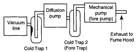
Fig. 30 Cold Trap 1 protects the diffusion pump, mechanical pump, and the user
from materials that could otherwise drift in from the vacuum line. Cold Trap
2 protects the diffusion pump from any oils that may drift from the mechanical
pump.
[ This vacuum region can only be achieved on special (usually metal) systems that can be baked.]
There are four basic foreline trap designs (and one post-pump trap):
1. Cold traps that rely on condensation or freezing to trap a condensable vapors.
2. Paniculate traps that physically block the passage of large pieces (>2 microns) of materials from getting into mechanical pump.
3. Molecular sieves primarily used to trap hydrocarbon oils-they also trap water vapor to a limited extent.
4. Coaxial traps that contain various fibrous materials loosely strung within the container to trap (primarily) pump oils. Table 10 provides a list of the various traps and their effectiveness against various vacuum system contamination.
5. Mist traps limit the amount of the aerosols of mechanical pump oils from leaving the pump and drifting into the room containing the pump.
These traps are different from the other traps in that they go on the exhaust of the mechanical pump and do not protect the pump or the sys tem, only the operators.
Cold traps use either water, dry ice slush baths, or liquid nitrogen as a coolant.
The low temperatures of a cold trap cause condensable vapors to change their state of matter into a liquid or a solid depending on the temperature and the vapor.
As temperature decreases, there is an increase in price and an increase in performance.
Water-based cold traps have limited efficiency, although they are the most cost effective. They can liquefy water vapor and many hydrocarbon solvents, but they can't entrap these materials. Thus, they are capable (and likely) to revaporize back into the system. The cost of running tap water through the cooler and down the sink can be eliminated by running a recirculating pump in a large plastic bucket.
The effectiveness can be enhanced by periodically dumping crushed ice into the bucket, but this does take constant maintenance of placing more ice as necessary and removing excess water as necessary (a drain placed on the top can decrease that concern).
Slush baths are effective for a greater range of vapors and can entrap many vapors by freezing. These types of cold traps require a lot of maintenance.
The most efficient type of cold trap is one that uses liquid nitrogen. This is because it is so cold that once captured, water, hydrocarbon solvents, and most other vapors will not be released into the system. Liquid nitrogen cold traps also enhance pumping within the system due to their cryogenic capabilities. Unfortunately, they are not without problems or complications. Probably the biggest handicap is that they require constant attention to maintain filling levels. Every time the coolant level goes below the level of frozen vapors, the pressure in the system will increase (see Fig. 32). Additionally, liquid nitrogen and its equipment are expensive.
Molecular sieve traps (and Micromaze traps from the Kurt J. Lesker Co.) have low maintenance and low long-term costs. Their main advantage is that, once bound, vapors are trapped till they are released by heating their active materials.
Thus they do not have the periodic pressure fluctuations that cold traps have. Their main disadvantage is that they require regeneration of the sieve by baking at 150 300°C about every 300 hours (or less) of use, and the regeneration requires many hours. The vacuum section must be closed off during the bakeout; otherwise, already-trapped hydrocarbons are dumped right back into the system. Because it is recommended that any valve between the trap and the system be baked as well as the trap,* this whole section cannot be made out of glass. There is no problem with a glass-to-metal connection of some type (except a polymer based o-ring seal) placed a sufficient distance away from the valve and the glass system. One can also have removable cartridges on the trap allowing one to remove the cartridge for regeneration away from the vacuum system. The advantage of this approach is that one sieve can be baked and ready to go, limiting downtime. Otherwise, this type of trap requires a long downtime during the bake-out period; thus this design may not be acceptable to all users. Some molecular sieves allow for easy removal of charging material, whereas others do not. Roepke and Pung devised a simple homemade molecular sieve with a removable charge unit.
Backstreaming can be one of the main limitations for mechanical pumps to achieve a better vacuum. Because molecular sieve and Micromaze traps are so efficient at capturing (and not releasing) vapors, Strattman [37] experimented with a Micromaze foreline trap to trap the hydrocarbon oils from a mechanical pump.
After proper baking and cooling, he was able to achieve pressures of 10^-5 torr consistently with only a mechanical vacuum pump.
Participate traps are simply physical barriers, or screens, that catch particulate matter just as the screens in clothes dryers catch lint. If your processes create particulate matter, it is very important to prevent it from getting into a mechanical pump of any kind. These traps can slow the pumping speed to some degree, but that is a small price to pay to prevent damage to the pump. Only particulate traps can stop particulate matter; no other trap can do so in an effective manner and should not be expected to perform this function.
Coaxial (or assimilation) traps utilize an adsorbing material drawn out to a fine fiber to provide as much surface area as possible. The various different materials available provide varying capabilities. For example, copper provides the best absorption capabilities (particularly to hydrocarbon oils), but is not very durable and needs to be replaced often. Stainless steel (particularly good for acid environments) and bronze will survive better in tougher environments, and activated alumina is great when organics or pump oils need to be trapped. Like molecular sieves, these traps work at room temperature. Unlike molecular sieves, not all can be baked out for regeneration and typically must be replaced with the old one discarded in an environmentally safe manner because it is likely to contain a variety of harmful materials.
[The coolness of a non-heated valve will become a condensation point for any hydrocarbons that are baked out of the trap. This forces contamination into a region next to the system that the trap is trying to prevent.]
Mist traps trap oil aerosols (> 0.3 microns) from the exhaust port of mechanical pumps to minimize exposure to workers in the area. Since they cannot trap gases, vent tubes going to fume hoods are still recommended (see Fig. 14).
All traps designs require proper use and maintenance. Mistakes, or improper use, can at a minimum backfill your system with the hydrocarbon oils you are trying to prevent from getting in there to the condensable vapors you are trying to remove. All trap designs should have a valve between the trap and the system to prevent cross-contamination during periods of nonuse. Any trap design that allows baking should have some barrier that limits (or prevents) human contact with the trap while heating is taking place to prevent burns. Because liquid nitro gen cold traps present special safety and use concerns, the next two sections pro vide more detailed instruction of their use.
4.3 Proper Use of Cold Traps
It is not uncommon for those using vacuum systems to consider trap functionality as limited to catching condensable vapors as they leave the vacuum system on their way to the pumping devices. It all too common for people to forget that besides the trap protecting the pump(s), the traps also protect the vacuum system from materials backstreaming from the pumps. Optimally, this second (but no less important) function of traps increases potential vacuum by limiting backstreaming.
For something so important, it is surprising how neglected the traps on a vacuum system are, and how poorly they are maintained. Just as one can do significant damage to a car by neglecting the oil filter and motor oil, many a vacuum system is not performing as well as it could due to a few oversights to trap use.
Aside from the issue of maintenance, issues for optimum system performance should include trap selection, how the trap is designed, and how the trap is attached to the vacuum system.
For the many vacuum processes that do not generate, or release, any significant quantities of condensable vapors, trap orientation is for the most part irrelevant. However, for the many other vacuum processes that do generate, or release small to significant quantities of condensable vapors, the orientation can have significant ramifications. If the liquid nitrogen trap is attached the one way, there can be a build-up of excess frozen materials in the center tube resulting in a reduction of the trap's throughput. With sufficient amount of vapors, this reduction could eventually lead to a complete cutoff of all gas flow through the trap (see Fig. 31). By simply orienting the trap the other way, the buildup of frozen vapors collects on the outer wall, leaving the center tube free for gas transport.
In addition to more efficient throughput, the trap arrangement on the right of Fig. 31 allows one to remove the condensate while frozen. This helps prevent the condensate from drifting back into the system after it has defrosted, and if there are any particularly dangerous materials, they can be moved to a fume hood for dealing with in a safe manner.

Table 10 Trap Selection
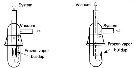
Fig. 31 If a cold trap is improperly oriented, the system may clog up.
There is an argument in favor of the design on the left of Fig. 31: If there is poor trap maintenance, and the frozen vapors defrost (and collect on the bottom of the trap), there is no chance for these liquids to be sucked into the pumps by someone throwing a switch or stopcock at the wrong time. However, for this amount of liquid to reach the level of the inside tube indicates poor trap maintenance. In addition, this amount of condensate had to have effected gas transport.
Constant removal of the trapped materials should always be done, but with this orientation, it is less critical.
One other disadvantage of the reduced throughput orientation is that as the vacuum improves, the trap's ability to trap decreases. This is due to less air to conduct the cold of the coolant to the inside of the trap. The continuous throughput orientation, on the other hand, has the coolant on direct contact with the outer walls of the trap, ensuring a constant temperature at any vacuum.
The best throughput is obtained by using the ratio that Dushman recommends where the inside diameter of the inner tube divided by the inside diameter of the outer tube. When this ratio is 0.62, the cold trap's throughput is at its most efficient, regardless of the orientation.* Rosebury studied the ratio between the inside and outside tube with consideration to the length of the cold trap for maxi mum trapping efficiency. He found that a short, fat cold trap has much better conduction than a long, thin cold trap, but such a trap's ability to trap condensable vapors will be severely handicapped due to limited opportunities for the vapors to come into contact with a wall. Although there is a penalty for a longer trap, if the ratio of 0.62 is maintained, maximum (for that length) conductance will be at a maximum.
[* If the traps are oriented as shown on the right of Fig. 31, the quality of throughput is maintained regardless of the amount of frozen vapors.]
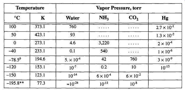
Table 11 Vapor Pressure of Various Substances as a Function of Temperature
Improper selection of coolant for a cold trap may artificially limit the potential vacuum of your system. For instance, the vapor pressure of water (which is often the primary condensable vapor in many vacuum systems) is quite high without any cold trapping, moderate at dry-ice temperatures, and negligible at liquid nitro gen temperatures (see Table 11). If your vacuum needs are satisfied within a vacuum of 5 x 10^-4 torr, you can safely use dry ice (and save money because dry ice is less expensive than liquid nitrogen). Another temperature option for a cool ant is the slush bath (for more information on coolants see Section 6.2).
Starting a vacuum system should include the following trap use procedures for safe and efficient vacuum system operation:
1. Prevent Air (Oxygen) from Condensing within the Cold Trap. One of the more common laboratory accidents can occur when air (oxygen) is frozen in a cold trap. This accident is caused by placing a cold trap within liquid nitrogen while there is still sufficient oxygen within the trap to be condensed. Later, once the liquid nitrogen is removed (either intentionally or is boiled off) the condensed air vaporizes. The excess pressure created by this frozen air can result in anything from stopcock plugs being blown across the room to an explosion of the entire line. Many labs have "horror stories" of these potentially dangerous, and always costly, occurrences.
To prevent oxygen from freezing in cold traps, be sure that there is no air in the trap when pouring liquid nitrogen around the cold trap. If you suspect that you may have air condensed in the cold trap, be sure the frozen air has room to expand. There are three ways to prevent explosions from frozen air:
1. Leave that section of the vacuum system in a continuous state of vacuum, never bringing it up to room pressure. (This is not always possible because traps often need to be removed to empty their contents.)
2. Begin pumping with the mechanical pump for a few minutes to make sure that the trap is below =1 torr before placing liquid nitrogen around the cold trap. A pump running against atmospheric pressure is noisier than one running against a vacuum. Thus, once the pump noise has dropped, it is safe to place the trap within liquid nitrogen.
3. Leave a stopcock open (to the atmosphere) at the end of an experiment to vent the system after the work is done. However, if you do this, be sure to remove the liquid nitrogen from the trap before opening the vent. Otherwise you will be condensing oxygen that is drawn in by the open vent.
Suggestion 1 should always be practiced whenever possible. The re-entry of atmosphere into a vacuum system reintroduces copious amounts of moisture onto the vacuum system's walls and reintroduces gases back into the liquids within your system (oil and/or mercury). The next time the system is used, the walls will need to be re-dried and the liquids re-outgassed. Thus, a greater amount of time than would otherwise be necessary will be required the next time you wish to obtain a vacuum. This extra time will also place more wear and tear on your pumps and expose them to extra condensable vapors.
Suggestion 2 should always be done as standard practice. Assuming your traps are emptied of liquids and condensable vapors, there should be nothing available to damage the pumps. Therefore, the practice of running the pumps for a few minutes (before placing liquid nitrogen around the cold traps) helps ensure that an insufficient amount of air is available for the oxygen to be condensed.
Suggestion 3 has limited practicality. It can only be effective after work on the vacuum line is complete and you wish to shut down the system. This plan will not help vacuum lines left unattended and/or whose liquid nitrogen has boiled off.
Regardless, if frozen oxygen boils off faster than can be released by the vent, the results would be the same as if no vent were available. Thus, the potential for disaster is still present.
In practice, use Suggestions 1 and 2. It is better to ensure that no air freezes within the system than to develop techniques to deal with problems that should be avoided.
Frozen oxygen will appear as a lightly blue-tinged liquid in the bottom of the trap. Oxygen is one of the few materials to remain a liquid at liquid nitrogen temperatures.
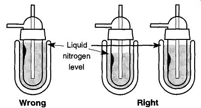
Fig. 32 By filling the liquid nitrogen to the top of the Dewar when first cooling
the cold trap, the user risks limiting the maximum pressure the system can
achieve.
However, by keeping the level low in the beginning, the user can keep any frozen material locked up.
2. Limit the Amount of Moisture Near the Top of Your Cold Trap. A common error when first starting up a vacuum system is pouring liquid nitrogen too high into a Dewar. People often overfill Dewars in the early startup process because the liquid nitrogen boils off initially very quickly, so there is a reaction to overfill. This overfilling can limit the potential vacuum of a vacuum system and/or create unaccountable pressure blips.
The problem originates because the liquid nitrogen high in the Dewar freezes moisture in the upper regions of the cold trap (see Fig. 32). Later, as the liquid nitrogen boils off, the moisture at the top of the trap evaporates (because nothing is keeping it frozen) and the pressure in the system rises, thus becoming a virtual leak (see Section 6 on Leak Detection), which is very difficult to find because no one thinks to look for a leak within a cold trap.
Fortunately, it is relatively easy to limit the degree of this problem by maintaining a low liquid nitrogen level in the Dewar when starting your system. Later, by maintaining a high liquid nitrogen level, any moisture that is trapped in early on will stay frozen. Unfortunately, that does not allow later collection of liquids to enjoy the same protection. The best defense for this problem is to maintain a high coolant level throughout cold trap use.
This virtually leaking cold trap problem is more likely to occur when first starting a vacuum system, or when a system has been down for an extended time because there is more moisture is in the system. The problem is more difficult to control when you are constantly cycling from atmospheric pressure to a vacuum state because moisture is constantly being brought into the system and the greater amount of liquid nitrogen being boiled off. The problem will always exist if your work creates copious amounts of condensable vapors stopped within the cold trap.
4.4 Maintenance of Cold Traps
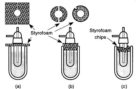
Fig. 33 Various methods of covering Dewars using Styrofoam. Be sure that
whichever approach is used, you allow a route for gases to escape.
[If the filling lines are overly long, any warmer gas (already in the line) may warm the Dewar some what before the liquid nitrogen arrives and may cause small pressure blips. In a study by Brown, it was found that white protective wrapping tape made a small, but notice able, difference in how long liquid nitrogen would remain in a Dewar as opposed to no tape or black electrical tape.]
There are two types of cold trap maintenance: (1) maintaining the liquid nitrogen (or the coolant of choice) at a proper level while the trap is in use and (2) maintaining clean traps to ensure the best throughput.
Maintenance of Liquid Nitrogen. A variety of automatic filling devices have been designed to maintain the liquid nitrogen level within a Dewar. Many of these devices are available commercially, and many others are sufficiently simple for lab construction. If you use an automatic filling device, try to limit the length of the filling lines.* In lieu of mechanical or electrical automatic filling devices, periodic inspection and manual refilling is always available.
Perhaps more important is limiting the amount of liquid nitrogen lost by boiling off. First, use a good-quality Dewar that is larger in radius than the cold trap by about 2 cm on all sides. All Dewars should be wrapped with tape f to prevent flying glass in case of implosion. If you ever notice frost on the outside of a Dewar, it is likely that the protective vacuum within the Dewar is gone and the void has filled with atmosphere. This occurrence is not uncommon and is caused (typically) by a poor-quality tip-off of the Dewar when it was evacuated.
Additional liquid nitrogen protection can be obtained by placing some insulation on top of a Dewar, which otherwise is exposed to the atmosphere. This insulation can be as simple (yet effective) as cardboard placed over the top of the Dewar, leaving a cutout for the cold trap. Styrofoam, a more efficient insulation material, can also be cut out and placed on the top of the Dewar [see Fig. 33(a)].
Alternative approaches include cutting Styrofoam into a cork shape [see Fig. 33(b)], or sprinkling crushed-up Styrofoam on top of the liquid nitrogen [see Fig. 33(c)]. Each of these approaches has good and bad points: Approach (a) can be knocked off easily and provides the least amount of insulation. How ever, it is easy to make and allows for easy examination of the liquid nitrogen level. Approach (b) provides excellent insulation abilities, but is not as easy to make and is more difficult to put into place. It is also more difficult to examine the liquid nitrogen level. Approach (c) is the easiest to make (just crush up some Styrofoam), but can be messy and locating the level of liquid nitrogen can be confusing or difficult. In a high-humidity environment, water vapor can freeze over the crushed-up Styrofoam, making refilling the Dewar with liquid nitrogen very difficult. Regardless of which approach you use, there must be a route for built-up gases to escape, otherwise the plug could be blown out with some force.
Maintain a Clean Trap. During vacuum operation, a trap may become sufficiently filled that emptying the trap is necessary. To empty a trap the lower section must be removed from the system, and to remove the lower section the trap must be vented to the atmosphere. If the trap is not vented, separating the lower removable part of the trap from the upper section could be like separating the Magde burg hemispheres (see the historical review in Section 2.3). If brawn is greater than brain, one could damage your system.* Unless there is a reason to vent the entire system, do not. When a system is exposed to the atmosphere, moisture can re-saturate the walls of the system, and gases can be resorbed into the vacuum liquids (diffusion pump oils and/or mercury). Extra (wasted) time will be required to return the system to its original vacuum condition. In addition, if your diffusion pump uses hydrocarbon oils, air can destroy the diffusion pump oils (if the oil is hot when the air makes contact) and the oils will then have to be replaced. All this wasted time and money can simply be avoided when first constructing vacuum system with a venting stopcock on the trap side of the system to vent the trap to atmospheric pressure while leaving the rest of the line in a vacuum (see Fig. 34).
Incidentally, if your work creates a constant buildup of material in the cold traps, have extra trap bottoms available. This preparation allows you to remove a filled trap bottom and transfer it to a fume hood while immediately replacing another on your vacuum line, thus significantly cutting down the amount of "downtime" on your system.
Following Fig. 34, if you need to temporarily remove the base of a trap while a system is in use:
1. Close Stopcocks 1 and 3.
2. Open Stopcock 2.
3. Remove base of cold trap.
4. Replace base of cold trap.
5. Close Stopcock 2.
6. Open Stopcock 3.
7. When the pump quiets down, replace Dewar under cold trap.
8. Open Stopcock 1.
It can facilitate separation to use O-rings on traps rather than standard taper joints because they are always easy to separate in either cold temperature or room temperature.
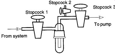
Fig. 34 Using valves or stopcocks to separate the various parts of your
system allows you to open sections of your system while maintaining a vacuum
in the rest of the system.
Removing the base of a cold trap while it has been in liquid nitrogen can be difficult, especially if the trap uses standard taper joints. The cold temperatures can make (even fresh) stopcock grease sluggish and firm. The easiest way to separate the base from a trap is to let the trap come to room temperature. The joint may also be easier to separate if you aim a hot air gun around the entire circumference of the joint (do not aim the hot air gun at one spot and expect it to heat the other side). If you need to use a hot air gun to soften the stopcock grease, be sure the stopcocks to the system and the mechanical pump are closed to prevent the trapped materials from being re-released to where they shouldn't get into. If you expect to remove a frozen trap often, consider using O-ring joints which are easy to separate (once vented) regardless of temperature.
When shutting down a vacuum system, close off your system from the trap section. That way, as trapped compounds warm up and go into a vapor state, they will not be able to drift into the rest of the vacuum line. You should also vent your pump to the atmosphere. Many pumps do not have adequate check valves near their oil reservoirs. If they are shut off with a vacuum on the vacuum side, the mechanical pump oil can be drawn up into the system. So, to shut down a vacuum system (see Fig. 34), it is recommended that you:
1. Close Stopcock 1.
2. Remove coolant (i.e., liquid nitrogen).
3. Turn off Pump.
4. Open Stopcock 2.
4.5 Separation Traps
All of the traps mentioned so far protect the vacuum line, pumps, pump liquids, and/or the people using the system. There can be other traps on vacuum systems whose function is not for protection, but rather as tools for chemistry. Separation traps fall into this category and can separate a mixed compound into different fractions by using the appropriate freezing temperatures.*
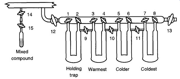
Fig. 35 Separation traps connected to a vacuum line.
Separation traps are typically a collection of interlinked U-shaped traps attached off the main vacuum line by two stopcocks (see Fig. 35). This arrangement allows separations of the mixed compound into as many traps as your system has.
Once separation is complete, any fraction of the separation may be removed from the system at any time and in any order. The contents within a trap may even be sent back to the main holding trap for further separation. The following will pro vide a generalized procedure for utilizing such a separation process:
1. Attach your sample to the system at Stopcock 14.
2. Open Stopcocks 14, 12, 13, 1, 3, 5, and 7 to evacuate the separation line and all the "U" traps.
3. After the extension line on the vacuum system has been evacuated, close all stopcocks except 14 and 12.
4. Place liquid nitrogen (in a Dewar) around the holding trap.
5. Stopcocks 15 and 1 can be opened; and using the cold from the liquid nitrogen as a sorption pump, transfer the mixed compound into the holding trap (you may want to lightly heat the original compound to facilitate the transfer).
6. Close Stopcock 12 and 1.
7. Place Dewars, with the appropriate temperature slush baths, under the other traps on your system. The Dewar closest to the holding trap should have the warmest of the cold temperatures, and the Dewar farthest away should have the coldest bath.
8. Remove the Dewar from the holding trap, empty it, and replace the Dewar (this procedure allows a slow warming of your mixed compound). Open Stopcock 9 (or 2 and 3) and allow the compound with the highest vapor pressure to freeze out.
9. After a sufficient amount of time has elapsed, open the stopcocks to the successive traps in similar succession.
10. Once the material in the holding trap has successfully passed into the other traps, close all stopcocks. Then, transfer the purified materials, one by one (from the lowest vapor pressure to the highest), back into containers such as those that originally held the mixed compound.
4.6 Liquid Traps
The most efficient way to prevent the liquid from an oil or mercury pressure gauge or bubbler from spilling into the rest of your vacuum system is to place a liquid trap between the liquid container and the vacuum system. The liquid trap design is fairly straightforward (see Fig. 36), and the installation of one is strongly recommended.
The beauty of liquid traps is that once in place they require no further oversight, care, or maintenance. Once you have seen the damages caused by a manometer or a McLeod gauge that has "burped," you understand the value of liquid traps. How ever, the value of liquid traps can be overemphasized, and they should not be used as panaceas for clumsy vacuum work. They will not stop all the mercury (or other fluids) that are being battered around within a system, so do not depend on liquid traps to make up for carelessness.
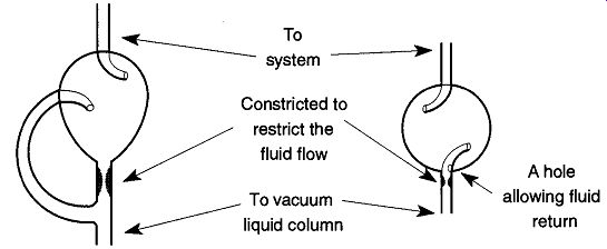
Fig. 36 Two liquid trap designs.: In this trap, fluids travel the easier
route of the side arm (rather than the constricted center tube) and splash
into the pear-shaped flask. From there they pour back into the container
from where they originally came.
In this design, fluids are splashed against the inside wall where they can flow back into the tube from the hole on the side of the lower tube.
5. Vacuum Gauges
5.1 The Purposes (and Limitations) of Vacuum Gauges
The two most common reasons to know the quantitative level of vacuum in a sys tem are either to know that a general level of vacuum has been achieved (so that something else can be done), or to see what quantitative effects an experiment has had upon the vacuum. The former requires a type of "go/no-go" reliability that may or may not have accuracy requirements. The latter is important with experiments such as gas creation or changes in vapor pressure. For proper analysis of experimental data, highly accurate readings are required. Regrettably, the greater the vacuum desired, the less reliable, or consistent, a vacuum reading is likely to be.
To obtain accurate and consistent low-, high-, and ultrahigh-vacuum readings requires years of experience and training beyond the scope of this guide. This guide explains the basic operation of common gauges and (hopefully) will give you the background to obtain the years of experience. Accuracy, however, is a somewhat loose term when used for vacuum gauges because actual (real) pressure must be experimentally determined.
The reading that one obtains from a vacuum gauge can depend on factors as diverse as system use, experimental technique, the gauge angle of attachment, external magnetic fields near the gauge, and ambient gases within the vacuum system. The formal definition for accuracy by the ISO (The International Standards Organization) is "the closeness of agreement between the result of a measurement and the true value of the measurement."
To maintain the best possible accuracy, recalibration is required to maintain the closest possible agreement with the manufacturer's stated accuracy. In addition, recalibration may be required each time a new gas species is introduced to a system. Unfortunately, all vacuum gauges tend to show a loss of accuracy over time, and this process continues over the life of the gauge. Recalibration cannot restore this lost accuracy, nor can re-calibration prevent error.
There are two basic ways for a vacuum gauge to "read" a vacuum: direct and indirect. For example, say that on one side of a "wall" you have a known pressure, and on the other side of the "wall" you have an unknown pressure. If you know that a certain amount of deflection implies a specific level of vacuum, and you can measure the current wall deflection, you can then determine the pressure directly.
This process is used with mechanical or liquid types of vacuum gauges. On the other hand, if you know that a given gas will display certain physical characteristics due to external stimuli at various pressures, and you have the equipment to record and interpret those characteristics, you can infer the pressure from these indirect measurements. This indirect method is how thermocouple and ion gauges operate.
Each method of vacuum reading has its advantages and disadvantages. No single method of vacuum reading is entirely easy and/or comprehensive, and no vacuum gauge can read a full range of pressures or be wholly accurate on all types of gases. Thus, the vacuum gauge(s), controllers, and other peripheral equipment you decide to use on your system are dependent on what vacuum range you need to read, what level of accuracy you need, and cost.
Once you have decided on which vacuum gauge to use, you then need to consider where and how it should be attached. The vacuum gauge should preferably be attached near the area where the vacuum work will be performed. Pressure is determined by the number of molecules per cubic centimeter, and at low pressures a vacuum gauge located far away from where you are working may give a mis leading value. Despite Avogadro's law, at different pressures there may be a random distribution of molecules within the vacuum. These differences can cause gauges to provide inaccurate pressure readings. There are three reasons for this problematic condition:
1. In molecular flow, there is a time factor before pressure can equalize within a vacuum system. Small-diameter (and/or long-length) tubing can compound this problem.
2. If the entry tube to the gauge is too narrow (and/or long), the statistical movement of molecules to enter the gauge may be inaccurately low. On the other hand if the angle of the tube to the gauge is in direct line with a molecular stream, the count of molecules could be inaccurately high.
3. Ion gauges have their own pumping capability providing lower pressures in the gauge region than in areas located some distance away (see Section 5.19).
Finally, be aware that if you read 3.0 x 10^-3 torr from your vacuum gauge, that figure is not likely to be your "real" vacuum. Likewise, if you are trying to duplicate an experiment that is pressure-specific, and despite repeated attempts the experiment fails, your vacuum reading may be at fault, not you. Vacuum gauges, by their nature and design, are always inaccurate. In standard laboratory conditions, vacuum measurements that are ± 10% reliable are very difficult, and those that are ± 1% are essentially impossible.
The reasons for this imprecision can include the following:
1. The gauge may be inherently inaccurate.
2. The gauge may be calibrated for a different gas than what is in your sys tem.
3. The elements of the gauge may be contaminated.
4. The gauge may not be receiving a sufficient amount of time for proper equilibration.
5. The misalignment of parts within a gauge can alter the accuracy of readings.
6. Different components, or types of filaments, within the same gauge can alter the accuracy of readings.
Always have a valve (or stopcock) between your vacuum system and vacuum gauge (and any other component of your vacuum system) to allow unneeded sections to be shut off when not in use and limit contact with potentially corrosive materials. The less contamination a gauge is exposed to, the longer the accuracy and reliability of the gauge will be maintained.
There are five major families of vacuum gauge design. The gauge families are the mechanical (see Section 5.2), liquid (see Section 5.4), thermionic (see Section 5.14), ion (see Section 5.19), and other (in this guide I have only made passing reference to the momentum transfer gauge in Section 5.24). Each family has its own strengths and weaknesses, and many vacuum systems often will have two or more gauge families represented on a single vacuum line. This mixture is partly to allow uniform pressure readings from atmospheric to high vacuum (a single gauge cannot do both) or to provide periodic cross-reference and calibration.
[If there is any doubt whether the gases in your system may attack the materials of the vacuum gauge, ask the component's manufacturer.
For an unidentified type of quartz Bourdon manometer, an accuracy of about ±0.01% over 20% to 100% of its range, with regular recalibrations, has been reported.]
5.2 The Mechanical Gauge Family
The easiest way to see a quantitative vacuum measurement of a system is to look at a dial and read it. This direct reading can be done with mechanical gauges. The surface of mechanical gauges that come in contact with gases within a vacuum system can be made out of metal or glass (borosilicate or quartz), both of which can be fairly impervious to chemical attack.* Mechanical gauges rely on diaphragms, bellows, Bourdontubes, and capsules that are squeezed, pushed, pulled, twisted, and turned by the pressure on one side of the device to the vacuum that is on the other within a vacuum system. Mechanical gauges mechanically transfer this distortion to dials, mirrors, or pointers for reading. Many mechanical gauge designs can be quite accurate with proper calibration and monitoring. For recording purposes, or to translate extremely minor amounts of distortion into readable figures, a displacement transducer can be connected to the moving part of a gauge.
The advantages of mechanical gauges are as follows:
1. Ease of use and the ability to read a positive and negative pressure.
2. The ability to provide a constant (as opposed to intermittent) reading.
3. The ability to provide continuous recording during use (if properly equipped).
4. If the proper construction material is selected, there can be limited reaction, or no reaction, between the gauge and materials within the vacuum system.
The disadvantages of mechanical gauges are as follow:
1. Their inability to read below approximately 10^2 torr (although very accurate specially-designed mechanical gauges can read to approximately 10^4 torr).
2. They are sensitive to temperature changes and may be sensitive to pres sure changes.*
3. They are subject to the effects of hysteresis, or, rather, the tendency of materials to "remember" distortions and not return to their original shapes (mechanical gauges with glass distortion membranes will not have symptoms of hysteresis). Hysteresis of vacuum gauges can be diagnosed by the following symptoms:
(a) The sensitivity of the diaphragm may change with time.
(b) After prolonged use (especially with radical temperature and/or pressure changes) the diaphragm will show signs of aging.
(c) The "zero point" often drifts.
Mechanical gauges can be easily attached onto metal vacuum systems, however, due to the construction materials of mechanical gauges, it is often impossible to make a direct seal onto a glass vacuum system. If necessary, a Swagelok® or Cajon® Ultra-Torr® may be used for making a glass-to-metal seal.
The glass-to-metal seal may then be fused onto the vacuum system.
5.3 Cleaning a Mechanical Gauge
There are two primary maintenance problems with mechanical gauges: dirt and/or grease. Both are results of improper trapping. If you can see dirt or oil on the dial, it is dirty and will require cleaning. (If you can't see any contamination, that doesn't mean it's clean.) If your work has (or can create) particulate matter, install line filters to stop materials before they can get into areas of the system that may be damaged (such as mechanical pumps) or that are hard to clean (such as gauges). If it is possible to open up the gauge, gently blow the particulate matter away with a dry nitrogen spray. Do not use "plumbed-in" compressed air because the gas from compressed air tanks always carry moisture and oil vapors.
Oil on the dial is indicative of oil migration from the pumping system. Improper and/or inadequate traps or user error are to blame for this problem. Clean with an appropriate solvent for the type of grease found. Rinse and dry the gauge before reinstalling back onto the line. Methanol is a good final rinse as it dries quickly and cleanly.
[ Most gauges are sealed to the outside world and thus should be unaffected by atmospheric changes. ]
5.4 The Liquid Gauge Family
The liquid gauge family is identified simply as vacuum gauges that have some liquid (usually mercury or a low-vapor-pressure diffusion pump oil) directly in con tact with the vacuum. The amount of liquid movement is directly proportional to the force exerted on it, and the (measured) amount of movement is read as the vacuum. Because mercury has traditionally been used for vacuum measurement, the term "millimeters of mercury" is commonly used even with nonliquid gauges.
Low-vapor-pressure oils can be substituted for some operations, but calibrations for density must be made so that their measurements can be interpreted as milli meters of mercury, torr, or Pa. Unfortunately, vacuum measurements can take a considerable amount of time when using oil because it takes a long time for a film of oil to settle from the walls of a manometer.
Despite the limitations and problems that the liquid gauge family presents, per haps the biggest problem with the liquid gauge family is that its members can be very difficult to keep clean because the liquid is in direct contact with materials in the vacuum system. As mercury becomes dirty or contaminated, it tends to stick to the walls of glass tubing, thus decreasing its accuracy. As oil becomes dirty, its density can change and may provide inaccurate measurements. Realistically though, any vacuum system whose upper range is 10^3 torr is not likely to be significantly affected by limited contamination.
On the other hand, a liquid trap is essential between any liquid vacuum gauge and the manifold itself. The simplest accident can cause hours of needless delay as the vacuum line is cleaned out. Normally a simple splash trap is sufficient (see Section 4.6). Vacuum systems that go below 10 ^-5 torr should consider to have a cold trap placed between their liquid vacuum gauges and vacuum systems. This placement will keep vapors from contaminating either side of the system.
When a vacuum system is first started and brought from atmospheric pressure to a vacuum state, parts within the vacuum system need to be outgassed. When liquids are outgassed, they boil. This process needs to be done slowly, otherwise the liquids will "bump" (boil) violently, possibly causing the mercury (or oil) to splash across the system. This splashing could waste some time minimally by trying to get the liquid back into the gauge, or more time by requiring the system to be cleaned up; maximally, an extended period of time could be wasted by breaking the system. Therefore, slowly open the stopcock to your liquid manometer for outgassing (Section 5.8 provides specific information on how to let the liquid out gas in a McLeod gauge). It is not necessary to open the stopcock all the way to full open. If the stopcocks to the liquid vacuum gauge are kept closed to atmospheric pressures, the outgassing process needn't be repeated. However, if the gauge is brought to atmospheric pressure for an extended time (about a day), gases can re-enter the gauge and the full outgassing process must be repeated.
5.5 The Manometer
Second only to the mechanical gauge as the easiest device to measure and read a vacuum (and decidedly easiest in construction) is the liquid manometer (see Fig. 37). A well-made mercury manometer, kept very clean, can measure vacuums of up to 10^3 torr. This sensitivity can be increased by up to 15 times if a liquid with less density, such as diffusion pump oil, is used. However, diffusion pump oil is far more difficult to keep clean and can require either (a) a very tall (and thereby impractical) column or (b) a manometer of very limited range. In addition, because of the strong surface tension between diffusion pump oil and glass, long waiting periods between readings are required as the oil settles into place.
The mechanics of a U-tube manometer are simple: "The difference between the levels of two interconnected columns of liquid is directly proportional to the difference between the pressures exerted upon them, assuming equal capillary effects on both tubes.
In practice, one end of a manometer is attached to an unknown pressure, and the other end is attached to a reference pressure that is known. For all practical purposes, the known value needs only to be a much smaller order of magnitude than the unknown value.
By maintaining a manometer at a constant temperature, the liquid within will maintain a consistent density. From 0° to 30°C the density of mercury changes about 0.5%. Therefore, a consistent reading of accurate vacuums can only come from a consistent room temperature. Manometer reading techniques (see Fig. 38) are consistent and simple regardless of the design and type of manometer. All that is necessary is some basic subtraction, a good metric ruler, and a steady eye. The manometer is read by observing and measuring the difference of the mercury column heights within the manometer.
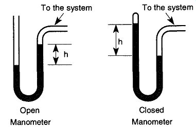
Fig. 37 Open manometers are used to measure pressures relative to atmospheric
whereas closed manometers are used for pressures far smaller than atmospheric.
From Vacuum Science and Engineering, Fig. 3-1, by C. Van Atta, © 1965 by
McGraw-Hill, New York.
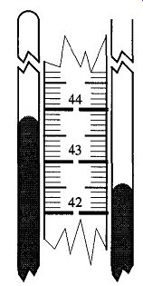
Fig. 38 In this example, take the measurement from the closed side (439
mm) of the manometer, and subtract from it the measurement from the side
of the manometer connected to the vacuum system (426 mm) to obtain the vacuum
reading (13 mm Hg). Remember, avoid parallax problems, and with mercury,
read the top of the meniscus.
The choice of mercury for manometers is often a matter of convenience, or rather the acceptance of the least amount of inconvenience. Mercury has a rather high vapor pressure (10^3 torr), but this vapor pressure is also at the upper ranges of what can be read by a manometer. Low-vapor-pressure oils (as used in diffusion pumps) can be used, but these oils wet the walls of a manometer and can take a long time to settle before reading can be made. Mercury is fairly nonreactive and retains a limited amounts of condensable vapors.
One of the biggest reasons why mercury is used is because it is a very heavy liquid. Atmospheric pressure can only push mercury about 76 cm, while it pushes water some 30 feet. Manometers using lighter-density liquids can be so tall they become beyond inconvenient. Additionally, because mercury doesn't wet the glass walls of the manometer, there is never a time lag for reading as there is with oil.
Fortunately, the mechanics of reading manometers is generally irrelevant to the amount of mercury (or any other liquid) within the device. Reading manometers can be difficult because of parallax problems. This difficulty can be complicated by the fact that manometers lack lines encircling them like burettes. Carroll found that by placing graph paper behind a mercury manometer, it was possible to see problems of parallax by the line's reflection off the glass and mercury (see Fig. 39).
For very accurate manometer readings, the NIST (National Institute of Standards and Testing) has a compiled list of eight possible errors that can develop while reading manometers.
These errors introduce extremely small variations and therefore are not included here. If you need to read a manometer to the sensitivity required for these variations to show up, it is better to use a different gauge type with higher sensitivity.
At first glance, it seems that one ought to be able to attach a vacuum line 77 or 78 cm above the lowest part of a gauge because at STP it is not possible for a vacuum to pull mercury any higher than 76 cm. While it is true that a vacuum cannot pull mercury higher than 76 cm, momentum can. If the mercury is being out gassed or there is an unexpected pressure surge, momentum can carry the mercury farther than your worst nightmares. Therefore, always include a liquid trap on all liquid systems (see Section 4.6).
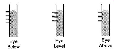
Fig. 39 Using graph paper lines to help avoid parallax problems while
reading manometers. From the Journal of Chemical Education, 44, p. 763 (1967).
5.6 The McLeod Gauge
Rather than using mercury as a piston that is pushed about by the forces within a vacuum system, the McLeod gauge traps a known volume of gas of unknown pressure and compares it to a known volume of gas at a known pressure using Boyle's law:
P0V0 = PtVf ( 13)
where:
Po is the original pressure
Vo is the original volume
Pf is the final pressure
Vf is the final volume.
The advantages of the McLeod gauge are as follows:
1. The wide range of pressures it can read.
2. Its great accuracy (McLeod gauges are used to calibrate electronic gauges).
3. Readings are unaffected by the type of gas species within the system (although condensable vapors can affect readings).
The disadvantages of the McLeod gauge are as follows:
1. It can only read the pressure at single points in time, not continuously as can mechanical or electronic gauges.
2. The McLeod gauge uses mercury, which can be a nuisance because the gauge is difficult to clean and may be illegal in some areas. In addition, back-streamed mercury can sometimes affect your work.
3. The McLeod gauge has no ability to compensate for condensable vapors.
McLeod gauges are always made of glass. Figure 7.40 shows two typical McLeod gauge designs. There are many different configurations and designs of the standard McLeod gauge, but all have the same general configuration:
1. A lower bulb for mercury storage.
2. An upper bulb whose volume has been accurately determined.
3. One capillary tube extending from the vacuum bulb with its other end fused shut (in Fig. 40 it is labeled Capillary B).
4. A second capillary tube (in Fig. 40, it is labeled Capillary A), both ends of which are attached to a larger tube.
5. A larger tube which connects the McLeod to the vacuum system.
Ideally, the McLeod gauge should only be open to the system when a vacuum reading is being made to limit the amount of mercury vapors back-streamed into the vacuum system as well as the amounts of materials that drift into (and contaminate) the McLeod gauge from the system. The mercury in a McLeod gauge must be kept clean because dirty mercury tends to stick on the walls of the capillary tubing and leave trails that prevent accurate readings. It is much easier to keep the mercury in a McLeod gauge clean than it is to clean the capillaries of a McLeod gauge.
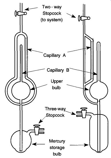
Fig. 40 Two common configurations of the McLeod gauge.
A liquid trap can be placed between the McLeod gauge and the rest of the sys tem to prevent mercury from accidentally spraying throughout your system. If you do not want condensable vapors affecting the McLeod gauge readings or do not want mercury vapors to enter your system, a cold trap can be placed between the liquid trap (shown in Fig. 41) and the main vacuum line.
Unfortunately, placing traps between the McLeod gauge and vacuum system increases the time needed to make a reading because the physical restrictions decrease the throughput and increase the time for gas equilibration. The efficiency lost by slower McLeod gauge readings (due to traps) must be balanced by other needs such as limiting the amount of mercury that gets into your system and/or keeping condensable gases out of the McLeod gauge.
An interesting problem occurs when a liquid nitrogen cold trap is placed between the system and McLeod gauge. The cold trap becomes a cryopump and draws mercury vapor from the gauge. This effect, called "mercury streaming," effectively limits the number of molecules that can enter the gauge (like salmon trying to swim upstream), and inaccurately low readings may result. Only readings in vacuums less than 10^4 torr are significantly affected, and atoms of higher molecular weights produce larger errors (i.e., xenon at 30% inaccurate readings).
5.7 How to Read a McLeod Gauge
There are two different methods of reading a McLeod gauge: One uses a linear scale, whereas the other uses a square scale. Because the square scale is primarily used, I will limit my explanation to its use. Refer to Fig. 42.
Always leave the stopcock leading to the McLeod gauge closed during experimental work to limit contamination entering the gauge and mercury from entering the system. When a pressure reading is desired, open the two-way stopcock that separates the McLeod gauge from the vacuum system. After the reading is completed, return the two-way stopcock to its closed position. Once the two-way stop cock is opened, slowly and carefully open the three-way stopcock (Position 1) to let mercury rise into the upper sections of the McLeod gauge by allowing atmosphere into the lower portion of the gauge.
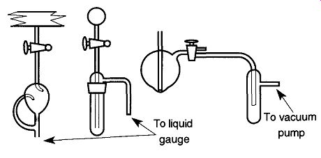
Fig. 41 Some traps should be placed between the McLeod gauge and the rest
of the system to prevent mercury from spilling into your system.
A liquid or cold trap should be placed between the McLeod gauge and the system. A manometer only requires a liquid trap.
A trap placed between the McLeod gauge and vacuum pump will prevent mercury from being accidentally sucked into the pump.
As mercury rises within the McLeod gauge, it is drawn up into the two capillaries. At this point, it is important to keep your eye on the capillary that is open on both ends (Capillary A). When the mercury gets closer and closer to the (inside) top of the second capillary (Capillary B), place your finger on the end of the open tube of the three-way stopcock to prevent air from entering the gauge. Your finger can provide precise control of the incoming air. Once the mercury reaches the height hlt stop the air from entering and make a reading. This method may take a bit of practice, but it soon will become relatively easy.* Once the mercury in Capillary A is the same height as the inside top of Capillary B, reading the pressure is done by simply drawing a visual line from h2 (the top of the mercury in Capillary B) over to the reading scale and reading your vacuum. In Fig. 42, the pressure is 0.04 |lHg, 4 x 10^5 mm Hg, or 4 x 10^5 torr.
After reading the pressure, rotate the plug of the three-way stopcock 180° to the #2 position to draw the mercury back into the storage bulb. Once the mercury is back in the storage bulb, turn the three-way stopcock 90° to a closed position.
Once a vacuum reading has been made, turn the two-way stopcock connecting the McLeod gauge and the vacuum system 90° to a closed position.
[If you overshoot the mark, simply turn the three-way stopcock to the #2 position for a moment pulling the mercury level down. It is not necessary to bring the mercury all the way back to the storage bulb, simply bring it below the /i, level.]
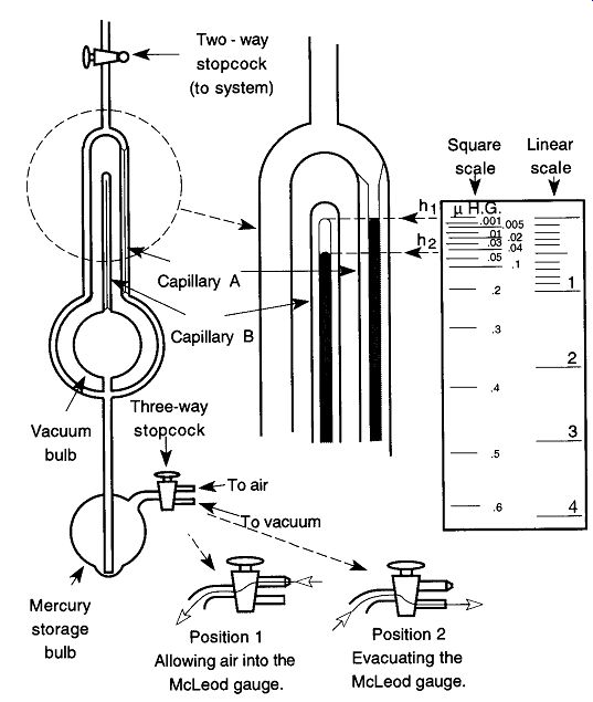
Fig. 42 How to use and read the McLeod gauge.
Despite being used for the calibration of other gauges, McLeod gauges are not perfect. There can be errors from physical limitations such as capillary depression phenomena, sorption and desorption from the gauge walls, and gas condensation within the gauge. Operator errors also exist such as difficulties of sighting the mercury heights properly. At 10^4 torr, the accuracy of a McLeod gauge is ±3%.
Assuming no operator error, at 7.5 x 10^7 torr (the upper limits of a McLeod gauge), inaccuracy can be ±15%. Specially adapted McLeod gauges can have their accuracy improved up to +0.9% and ±3.5%, respectively.
5.8 Bringing a McLeod Gauge to Vacuum Conditions
When first starting up a vacuum system from atmospheric conditions, do not expose a McLeod gauge to a sudden vacuum. Opening up the wrong stopcock at the wrong time can cause violent outgassing of the mercury. The mercury may be inadvertently sprayed throughout your system (despite traps) with enough force to break a line.
To bring a McLeod gauge to vacuum conditions and before turning the vacuum pumps on, be sure that the two-way and three-way stopcocks are rotated to their off positions. Then, turn on the vacuum pump and also do the following:
1. Slowly open the two-way stopcock a small amount, allowing the mercury to slowly rise from the storage bulb up to the bottom of the second bulb, then close the stopcock.
2. Slowly open the three-way stopcock to evacuate the McLeod gauge, drawing the mercury back into the storage bulb.
3. Repeat steps 1 and 2 several more times until the mercury enters the upper bulb very slowly and evenly. The number of repetitions is directly related to the volume of your system. Thus, the larger your system, the more repetitions of steps 1 and 2 will be required.
5.9 Returning a McLeod Gauge to Atmospheric Conditions
If you must return a McLeod gauge to atmospheric conditions, such as would be necessary for periodic regreasing of the stopcocks, the following procedures should be observed:
1. Slowly open the two-way stopcock (to system) allowing mercury into the McLeod gauge.
2. Close the two-way stopcock.
3. Open your system to the atmosphere.
4. Partially open the three-way stopcock to the atmosphere (Position 1).
5. Slowly open the two-way stopcock, letting the mercury fall back into the storage bulb.
5.10 The Tipping McLeod Gauge
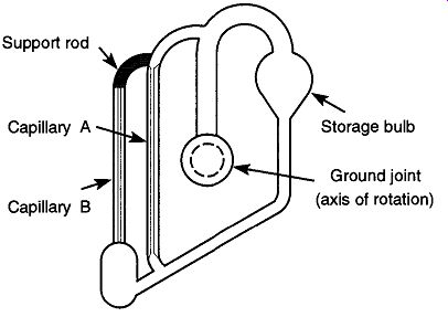
Fig. 43 The tipping McLeod gauge.
Figure 43 shows a tipping McLeod gauge. All of the same components found in a standard McLeod gauge are there (except the three-way stopcock), but in a significantly different configuration. It is much easier to use this gauge than to use a standard McLeod gauge, but it is less accurate and cannot read as low a vacuum.
Depending on the design, its lowest reading is from 0.050 to 0.001 mm Hg.
The tipping McLeod gauge can be mounted directly onto a vacuum system or can sit on a metal stand and connect to a vacuum system via a flexible vacuum hose. Regardless of the mounting technique used, there should be a two-way stop cock between the gauge and vacuum system that allows the user to shut off the McLeod gauge when it is not in use. This configuration limits the amount of mercury that backstreams into the vacuum system and the amount of material from the vacuum system that drifts into the McLeod gauge.
To operate the tipping McLeod gauge (see Fig. 44), do the following:
1. Open the two-way stopcock separating the gauge and vacuum system (not shown in Fig. 42).
2. Rotate by hand the gauge from the rest position to the vacuum measurement position.
3. Read Capillary B just as in Fig. 42.
4. After the measurement is read, release the gauge and it will rotate back to the rest position by itself.
5. Close the two-way stopcock off.
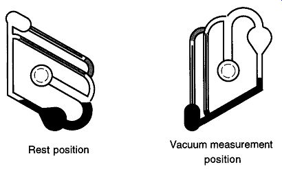
Fig. 44 How to use a tipping McLeod gauge.
Do not let a tipping McLeod gauge flop around too freely. Although the stop cock grease will cause some amount of drag, twisting the gauge too quickly from one position to another is likely to cause the mercury to spill into the closed capillary, where it can be difficult to remove. When the stopcock to the tipping McLeod gauge is closed, you are depending upon the static vacuum to keep the gauge attached to the line. There are metal clips that do assist this connection, and they should be used to help prevent accidental removal of the gauge from the line.
5.11 Condensable Vapors and the McLeod Gauge
Condensable vapors are gases near their condensation temperatures or pressures.
In the low pressures of a vacuum system they are gases. Examples of fluids that form condensable vapors at STP are water, alcohol, and mercury.
The McLeod gauge works on the ideal gas law principle that the pressure of a gas increases proportionally as its volume decreases. However, condensable vapors do not obey the ideal gas law and therefore, under standard use, the McLeod gauge cannot accurately measure them. Obviously, condensable gases with low vapor pressures at STP do not affect the readings of McLeod gauges significantly enough to alter the validity of the readings.
When a two-way stopcock is opened, all the gases (condensable and non-condensable) within the vacuum system can pass into the McLeod gauge, the vacuum bulb, and Capillary B. When the three-way stopcock is rotated, the gases that were in vacuum are brought to atmospheric pressures. Any condensable gases that "condense" at higher pressures will occupy less space. This "less space" will show up as a better-quality vacuum than really exists within your system. The McLeod gauge will indicate a lower reading equal to the vapor pressures of the condensable gases at their ambient temperatures.
To determine whether your readings from a McLeod gauge are being affected by condensable vapors, take measurements of hl and h2 for three to four levels (see Fig. 45). If the product of (h2 - hx) h2 is not the same but (h2-hx) = P (a constant) seems to hold, then you have at least one condensable vapor present.* With accurate measurements, Wear found it possible to identify the condensable vapors, estimate their concentrations, and determine the vacuum system pressure and partial pressure due to non-condensable gases. To avoid condensable vapor problems in McLeod gauges, limit the amount of condensable vapors that enter the McLeod gauge by using chilled or chemical vapor traps.
[To make these measurements, a special vacuum system is required. A complete derivation of the formulas and procedures can be found in the guide The Design of High Vacuum Systems and the Application of Kinney High Vacuum Pumps by CM. Van Atta, © 1955 by Kinney Manufacturing Division, New York Air Brake Company.]
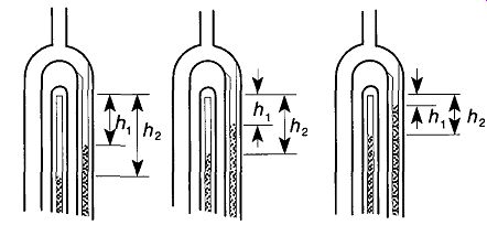
Fig. 45 By making linear measurements as the mercury rises within a McLeod
gauge, it is possible to determine whether there are condensable vapors within
the McLeod gauge.
5.12 Mercury Contamination from McLeod Gauges
There are two mechanisms for contamination from McLeod gauges: (1) contamination which is backstreamed into the system from the McLeod gauge and (2) contamination which comes from the McLeod gauge storage bulb during the evacuation process.
Research by Carstens, Hord, and Martin displayed a relatively high level of mercury being pumped out of a McLeod gauge during the evacuation process.
Typical readings (in mg/m^3 ) were Residual level 0.2 Evacuating reservoir 0.4. However, once a layer of low-vapor-pressure oil was added to cover the mercury in the storage bulb, the readings went down by a decade:
Residual level (with oil) 0.02
Evacuating reservoir (with oil) 0.05
The research authors pointed out that because the levels were erratic and low, the actual health dangers were also rather low.
One should also remember that the oil within the mechanical pump also becomes a trap for emitted mercury vapors. However, the mechanical pump becomes only a temporary trap for the vapors. Once in the pump, the mercury collects in little pools and is slowly emitted into the atmosphere. It has been observed that pump performance is impaired by mercury pools (found within the mechanical pump) by the author's personal observation.
Stopping mercury migration into a system can be achieved by placing a cold trap between the gauge and system. Stopping mercury contamination from a McLeod gauge's storage bulb can be achieved with a thin layer of low-vapor-pres sure oil over the surface of the mercury. This oil will not affect the gauge's performance in any way.
5.13 Cleaning a McLeod Gauge
Invariably, the mercury within a McLeod gauge will get dirty. The telltale evidence is when the mercury does not cleanly run down the glass tubing and/or you see a film on the surface of the mercury. Traps are the best way to avoid this problem.
A McLeod gauge must be removed from a system when it is being cleaned. This removal probably will involve the talents of a glassblower. The mercury should be carefully poured out of the gauge and sent to a mercury distiller for cleaning. The grease should be removed by an appropriate solvent. Silicon grease should never be used on a McLeod gauge because it requires far too much maintenance and replacement.* Dissolve any mercury remaining in the gauge with nitric acid. Heating the nitric acid will facilitate the cleaning^ Use gloves and work in a fume hood! After draining and thorough rinsing with tap water, there should be a final rinse with distilled water. If you choose to extend the process one more step with a methanol rinse to facilitate drying, be sure that all the nitric acid has been removed because the acid is not compatible with organic materials.
It can be very difficult to get liquid into various parts of a McLeod gauge because of the closed capillary tubing. One solution to this problem is to use a vacuum cleaning setup as shown in Fig. 46. A Teflon stopcock is used because it requires no grease.
When the stopcock shown in Fig. 46 is turned to one position, a vacuum will be created in the item to be cleaned. Rotating the stopcock 180° will allow the cleaning or rinsing solution to be drawn into the piece. Then by rotating the stop cock one more time while holding the item in a draining position, the liquid can be removed into a filter flask.
Do not break apart a McLeod gauge for easier cleaning. The calibration of the various parts is extremely accurate. Some McLeod gauges have sections that are intended to be dismantled and have ground glass joints between sections. Some tipping McLeod gauges have plastic end caps (on the closed tubes) to facilitate cleaning.
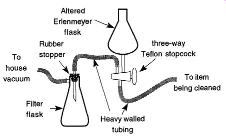
Fig. 46 Vacuum apparatus for cleaning hard-to-clean apparatus.
[ Silicone stopcock grease requires cleaning and replacement every month or two whether the stop cock is used or not. Nitric acid containing mercury is a toxic waste. It must be saved and disposed of under proper conditions and with licensed firms.]
5.14 Thermocouple and Pirani Gauges
Thermocouple and Pirani gauges both use the physical characteristic of heat (within a vacuum) to infer the amount of vacuum within a system. If an object is hot, the only way it can cool down is to transfer its heat to the surrounding area by conduction or radiation. The standard way this transfer happens is that the object conducts its heat through the air (and anything else it is touching) and radiates its heat with IR radiation to other surfaces. In a vacuum, there is less air through which a hot object can conduct its heat, and therefore it can only lose heat through conduction of the remaining air and IR radiation. Both gauges have fast response times and are excellent for determining pressures between 1 and 10^3 torr. They also can be used in leak detection.
Thermocouple and Pirani gauges both have filaments within them that are exposed to the vacuum of the system. These filaments are always under small, constant electric loads and, because of their resistance, they get hot. At higher pressures, the air/gas in the system conducts all the heat from the wire. As the vacuum increases, less heat can be lost through (air/gas) conduction, and more heat is then maintained by the wire. Once the vacuum is high enough, heat is lost primarily by conductance from the wires holding the filament and IR radiation, thus creating the lower limits of the gauge.
Both gauges are dependent on the thermal conductivities of the gases that surround them. Because different gases have different thermal conductivity, different gases will indicate different values for the same pressure. It is possible to adjust a gauge reading to a "calibrated accurate" pressure if you know the constant with which to alter the gauge reading. The real vacuum can be determined with Eq. (14) and the appropriate sensitivity constant. For a list of sensitivity constants, see Table 12. It is impossible to achieve either gauge's potential accuracy when measuring a vacuum system filled with unknown gases.
Pressure = Gauge reading / Sensitivity constant
Electrical Warning: These types of gauges generally do not use high voltage.
They do, however, use 110- to 120-V current, which means that common sense should be observed. For instance, do not pull on a cord when unplugging, but instead pull on the cord outlet. Avoid spilling conducting liquids around the gauges. All pieces should be grounded. If the unit has a three-pronged outlet, do not cut the ground off or bypass the ground by using a two-pronged extension cord. Unplug the unit if repair needs to be done. Replace worn and/or frayed cords immediately. Cover all bare (exposed) electrical leads with tape, tubing, shrink tubing, or plastic screw caps. In addition, keep flammable liquids or gases away from electrical devices in case of any sparks and/or electrical arcs.
5.15 The Pirani Gauge
The Pirani gauge uses the principle that (usually) the hotter a wire gets the greater its electrical resistance. Therefore, if the resistance of a wire is going up, it must be getting hotter. This relationship implies that less air/gas is available to conduct heat away from the wire, and therefore a higher vacuum is being achieved.
The accuracy of a Pirani gauge is typically ±20%, although an individual (clean) gauge properly used over a two-year period may show a sensitivity drift of only 2%.
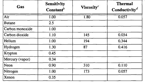
Table 12 Properties of Various Gases
One immediate complication of the Pirani gauge is ambient temperature: As the room temperature gets hotter, the filament gets hotter, making the gauge read a false "better vacuum" To solve this problem, a dummy filament is included in the Pirani gauge. The dummy filament is evacuated and sealed off (at a lower vacuum than what is likely to be used with the Pirani gauge) and is used as a standard to help calibrate a zero point.
[Adapted from Spinks, Vacuum Technology, Franklin Publishing Co., p. 22, and from Guthrie, Vacuum Technology, John Wiley & Sons., p 504 (1963).
* Sensitivity constant: These constants are accurate ± 10% over any given range of pressures.
Viscosity: At 15°C, given in micropoises.
Units are 103AT, where K = thermal conductivity at 0°C, cal/cm/sec/°C.]
An electrical diagram for a Pirani gauge is shown in Fig. 47, where V and D comprise the Pirani tube. D is the dummy filament tube that is sealed off, and V is the tube that is exposed to the vacuum system. The filaments in the V tube are connected to a bridge circuit called a Wheatstone bridge with two resistance units called R1 and R2. Power from the power supply passes across the Wheatstone bridge and is adjusted to the proper setting by R3, whose value is read on the milliammeter M2.
The current read on M1 is proportional to the vacuum. An ammeter will read the current, which is proportional to resistance in ohms.
To set a Pirani gauge, the vacuum on V is set to a pressure lower than what the gauge can normally read. Next Ml is set on its zero point by adjusting the resistance of R2. Thereafter M1 will give proper readings as the pressure is raised to the range of the gauge.
The advantages of a Pirani gauge are as follows:
1. It has a rapid response to changes in pressure.
2. The electrical circuitry in the gauge leads to easy adaptation to recording, automatic devices, and computer sensing.
3. Electrically it is very simple.
4. It measures the pressure of permanent gases as well as vapors.
The disadvantages of a Pirani gauge are as follows:
1. Because not all gases have the same thermal conductivity, different gases will provide different pressure readings for the same pressure.
2. It is limited to the pressure range of about 10^1 to about 10^4 torr.
3. If there is any change in the filament wire's surface condition within the Pirani gauge, there will be a change in the heat loss. This change will result in a change of the gauge calibration as well as a change in the zero.
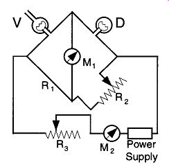
Fig. 47 Pirani gauge schematic.
5.16 Cleaning Pirani Gauges
If a Pirani gauge becomes contaminated with backstreamed oil, rinsing the gauge with a suitable solvent should be sufficient. Be sure to rinse with distilled water followed by a methanol rinse. Be gentle with the gauge so as not to break the internal wire, which is fragile. Cleaning is likely to change the calibration, so be prepared to recalibrate the gauge after cleaning.
5.17 The Thermocouple Gauge
The thermocouple gauge is more straightforward than the Pirani gauge and less complicated electronically. The thermocouple gauge has a thermocouple attached to a filament under constant electrical load, and it measures the temperature at all times. If the filament becomes hotter, it means that there is less air/gas available to conduct heat away from the wire, and therefore there is greater vacuum within the system.
There are two different types of thermocouple gauges: One has three wires and the other has four. Both have a dc meter (or voltmeter) that reads the voltage from the thermocouple. The three-wire unit uses ac to heat the filament wire, whereas the four-wire unit may use ac or dc. Although there are essentially no differences in performance between the two, they will likely require different controllers (or different settings) for use.
The advantages of the thermocouple gauge are fairly consistent with the four stated for the Pirani gauge with a few exceptions:
5. Thermocouple gauges can be made smaller and are more rugged than Pirani gauges.
6. Although the thermocouple gauge is subject to the same variations in apparent readings from real pressure (because of variations in the thermal conductivity of different gases), the differences are less apparent than the Pirani gauge.
The disadvantages of the thermocouple gauge are somewhat different from those of the Pirani gauge:
1. Because not all gases have the same thermal conductivity, you will get different pressure readings for the same pressure with different gases, although the differences for the thermocouple gauge are not as great as those for the Pirani gauge.
2. It is limited to the pressure range of about atmospheric to about 10^3 torr
3. The thermocouple gauge scale is nonlinear, but the readings can be accurately interpreted by the controller.
4. A thermocouple gauge should not be placed on any system with mercury unless there is strict controls set to trap and prevent the mercury from reaching the gauge. The reason for this is that the mercury can contaminate the wires of the thermocouple gauge and create false readings of a (virtual) leak (see Section 6.4).
Physical abuse, improper cleaning, and age can all cause a thermocouple to break. The symptoms may either be no response to the controller or a jerky twitching of the controller's needle. In either case, the thermocouple is not likely repairable and a new one will be necessary.
5.18 Cleaning Thermocouple Gauges
The thermocouple gauge is more durable than the Pirani gauge, which means that after you pour in the appropriate solvents for cleaning, you can shake the gauge for cleaning agitation. This cleaning procedure should be followed by rinses of water, distilled water, and, finally, methanol. There is no viable cleaning technique to remove mercury from a thermocouple gauge.
5.19 The Ionization Gauge Family
All previously mentioned gauges require a certain level of particle density for operation. Once the level of particle density has dropped below a certain level (approximately 10^18 particles/m^3 ), it is not possible to detect transfer of momentum forces either from gas to solid wall or from gas to gas. On the other hand, it is possible to ionize gas particles and then "count" the ionized molecules.
A molecule in a "normal" state has a neutral charge; there is an equal number of electrons and protons. If you subject the molecule to a high amount of energy and knock out one of the electrons, the molecule is now ionized with a positive charge.
This charge allows you to force the molecule to travel, bend, be focused (if necessary), and be counted. The number of (positive) ions created is always directly proportional to the molecular number density. It is only proportional to the pres sure if the temperature is known and kept constant, and the type of gas being analyzed has known calibration constant for the type of gauge you are using.
There are essentially two types of ionization gauges used in the laboratory: The hot- and the cold-ion gauges. A third type, the radioactive ionization gauge, is so limited in both scope and use that it will not be discussed in this guide.
The concept of the ionization (ion) gauge is quite simple. Under a given electrical load, the available gas within the vicinity of the vacuum gauge is ionized either by heat or by a high-field (electrical) emission. Then, the ionized gas is collected and counted. From this count you can interpret what you have read as a unit(s) of vacuum and thereby infer the vacuum within the system.
One ironic peculiarity of ion gauges is that the ions collected by the gauges for counting are not re-released to the vacuum system and therefore are bound up as in getter pumps. Therefore an ion gauge also acts as a pump. This feature itself sounds great: What vacuum system couldn't use a little extra pumping? However, this feature adds an accuracy problem because there is no way of knowing whether the vacuum within the confines of the gauge (where active pumping is going on) and the vacuum within the rest of the system is the same. Thus, to maintain accuracy between the pressure within the gauge and within the system, the gauge should not be left on for extended periods of time and the gauge should be connected to the system with large-diameter tubing. This setup decreases the opportunities for a pressure gradient to be established and facilitates equalization between the gauge and the system if a gradient condition occurs.
Hot-cathode gauges are considered fast pumps, but cold-cathode gauges pump 10 times faster. At 10^10 torr there are only 106 molecules per cubic centimeter. If a hot-cathode gauge's volume is 100 cm^3 , 1% of the gas within the gauge is removed every second!
It has been shown that if the conductivity of the connecting tube is >10 liters/sec, these affects are negligible.
If you are concerned specifically with accuracy, hot-cathode gauges show greater accuracy and reproducibility. However, it must be operated by an experienced technician in controlled conditions with repeated backing and degassing.
Otherwise, the cold-cathode gauge will provide greater accuracy without constant attention. This is mostly attributed to the how the electrodes of the hot-cathode gauge do get hot during operation which in turn provides some incidental outgas sing. The cold-cathode gauge operates at room temperatures and has no incidental outgassing.
Electrical Warning: Ion gauges require high voltage, so common sense must be observed. For instance, do not pull on the cord when unplugging a gauge from a wall outlet, but instead pull on the electrical plug. Avoid spilling conducting liquids around the gauges. All pieces should be grounded; and if the unit has a three pronged outlet, do not cut off the ground or bypass it. Be sure to unplug the unit if it is being repaired. Replace worn and/or frayed cords immediately. Cover all bare (exposed) electrical leads with tape, tubing, shrink tubing, or plastic screw caps.
Keep flammable liquids or gases away from electrical devices in case of sparks and/or electrical arcs. Because of the high voltages possible with ion gauges, dirt (and even fingerprints) can cause unexpected arcs. Therefore, keep the gauge surface clean. Turn off the gauge and its controller when helium leak testing because a discharge can be created around high-voltage feed-throughs, which in turn can destroy the gauges controller. Likewise, turn off the gauge and controller when checking for leaks on a glass system using a Tesla coil. The discharge can destroy the electrical circuits within the controller. Finally, if your vacuum system is mounted on a metal rack, ground the rack with grounding strap (braided copper plated wire) to plumbing or some other substantial ground. For proper contact, file off any paint or corrosion on the rack and the ground before attaching the grounding strap with a threaded hose clamp.
5.20 The Hot-Cathode Ion Gauge
The most common hot-cathode ion gauge (and the most common high-vacuum gauge used) is the Bayard-Alpert gauge. It can read vacuums between 10^3 and 10^10 torr. With special gauges, readings as low as 10^14 torr can be obtained. A diagram of its general structure is shown in Fig. 48. The hot-cathode gauge operates by heating a filament, which causes an emission of electrons. These electrons are attracted to a grid which is held to a high (+) potential that attracts the (- ) electrons. As electrons stream toward the grid, they collide with the gas molecules enroute, ripping off an electron and creating positive ions. The positive ions are attracted to the ion collector, collected, and counted. The positive ion current is measured in amperes from the gauge tube, but the hot-cathode gauge controller then interprets this count as vacuum reading. Hot-ion gauges are designed to be gas-specific* Currently, the gauges are accurate to within ± 20% for their specific gas type.
Early versions of the hot-cathode ion gauge used a large cylinder for the ion collector. This design was limited to a vacuum measurement of only approximately 10^4 torr. Nottingham [56] proposed that when electrons struck the grid, soft X-rays were created. The X-rays then struck the large ion collector cylinder, which in turn caused photoelectrons to flow back to the grid. This action created a current in the external circuit of the ion gauge that was indistinguishable from the ion flow. Thus, the gauge was actually reading lower vacuums, but the excess electronic noise was masking the reading and producing artificially higher readings.
By decreasing the size of the ion collector, Bayard and Alpert significantly decreased the electronic noise, vastly improving the quality and accuracy of the hot-cathode ion gauge.
The standard material used for filaments within a hot-ion gauge is tungsten.* Unfortunately, a tungsten filament can easily burn out if a gauge is turned on when the pressure is too high within a system. Because of this idiosyncrasy, a thermocouple or Pirani gauge may be connected to a relay that shuts off power to the ion gauge if a loss of vacuum is detected. This addition is strongly recommended. (Some controllers provide automatic switching between a thermocouple and an ion gauge to allow for continuous readings between atmospheric and 10^10 torr.)
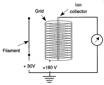
Fig. 48 The Bayard-Alpert hot-cathode gauge. From Fundamentals of Vacuum
Science and Technology, p. 92, by G. Lewin, McGraw-Hill, New York, 1965.
[Most gauges are designed to read specific pressures in nitrogen atmospheres.
Tungsten filaments can create large quantities of CO and CO2 during operation, which may, or may not, affect your work. It is possible to obtain Bayard-Alpert gauges that can be preheated, or baked out, prior to use to limit this problem.]
Another common filament material used in hot-cathode ion gauges is thoriated iridium (ThO2 on iridium). These filaments are used if there is any likelihood that the system will be exposed to accidental bursts of atmosphere. However, if exposed to hydrocarbons or halocarbons, their emissions can radically change.
Use of a silicon oil in the diffusion pump is required with these filaments. Recalibration of these filaments is constantly required.
Studies by McCulloh and Tilford found that dual tungsten filaments exhibited better linearity and also exhibited sensitivities which were in closer agreement to those stated by the manufacturer. Filaments made out of thoriated iridium demonstrated linearity differences as great as 30%. These differences were evident in standard as well as nude gauges.* Sensitivity variations can be due to (at least in part) the proximity of the top of the filament to the cylindrical envelope of the grid spiral (Hirata et al.).
This sensitivity is why (in part) gauges should not be roughly handled or dropped. If the filament changes its location within the gauge, the readings will vary from what they were before the mishandling. Any data that were obtained before such an incident may then need to be redone or re-calibrated to agree with later data.
Magnetic fields, depending on their strength and orientation, can also influence ion gauge readings. Studies by Hseuh showed that a magnetic field can change an electron's path even though changes in the collection of ions were negligible. A magnetic field has the least effect when it is parallel to the gauge. It has the greatest effect when the gauge is perpendicular to the magnetic field. However, the alignment of the electric field relative to a magnetic field is complicated. Optimally, it is best to keep magnetic fields away from Bayard-Alpert gauges.
[ A "nude" gauge has no protective cover and, rather than being attached to a vacuum system, it is mounted in the vacuum system. This difference prevents any lag in response time from pressure variations through a tube and eliminates the effects of ion-gauge pumping. The main disadvantage is that there is no way to shut off the gauge from the line itself, so there is no way of protecting the gauge from any potential contaminating materials. Nude gauges are not available for glass systems.]
There are several general rules to follow that will make the operation of a hot cathode ion gauge as trouble-free as possible. Implementation of these rules can not guarantee success, but ignoring them will ensure problems:
1. Always connect the gauge as close as possible to the area where measurements need to be made. The farther away the gauge is from the point of measurement, the longer the lag time before the system and the gauge come to equilibrium. The greater the vacuum (> 10^5 torr), the more pronounced this effect.
2. On glass systems, the ion gauge is attached to the line by a connecting piece of glass, a glass to metal seal, or some type of Swagelok®.
Regardless of how the gauge is attached, try to keep this connection as short as possible with as large a diameter of tubing as possible (>1 inch). Do not use any connection with a smaller diameter than that sup plied on the gauge. A cold trap placed between the gauge and line will help protect the gauge from condensable vapors. However, it will indicate pressures lower than really exist within your system due to the cryogenic pumping capabilities of the cold trap. In addition, it will also slow the speed required for the system and the gauge to come to equilibrium.
3. On metal systems, you have two choices: Connect the ion gauge by connecting tubing (same tubing size rules apply from Point 2), or use a nude gauge.
4. The ion gauge is gas- (see Table 13) and temperature-dependent.
Therefore, if your lab has temperature swings and/or you vary the gases within your system, constant recalibration may be required. Table 13 (and others like it) can only provide a benchmark for making corrections because your system is not likely to have pure gas samples. In addition, variations between gauges of the same type (but from different manufacturers) can be quite large while the differences between gauges of different designs can be phenomenal. For the most accurate interpretation of your gauges readings, obtain calibration tables from the gauges manufacturer.
5. Never turn a gauge on until the pressure is below 1 um or less. You must have a second gauge for higher pressures (for example, a Pirani or thermocouple gauge).
6. The hot-cathode gauge must be outgassed every time the gauge is exposed to the atmosphere for an extended period of time, or at pressures near the base pressure of operation (10^5 torr). The outgassing cannot be done at any higher pressure than 10^5 torr, and it can be per formed either by providing a current to the grid within the gauge (which can often be supplied by the gauge controller) or by electron bombardment. Note that some gauges can only be resistively heated or electron bombardment degassed. Gauges that require outgassing will read a pressure higher than really exists. The amount of error is dependent on the degree of outgassing required.
Regardless of the outgassing approach used, filament temperatures of about 800°C are required. Initially, a new gauge may need to be outgassed for some 15 20 minutes. If a gauge is showing evidence (i.e., dirty electrodes) that outgassing may be required again, some 15 seconds should suffice. During degassing, the ion gauge envelope becomes very hot. Be sure that the gauge is mounted in such a fashion that accidental contact with technicians or flammable materials is not possible.
If a gauge is outgassed at too high a pressure, a layer of metal (from the electrodes) may be deposited outside the gauge envelope (some controllers prevent degassing at too high a pressure). This condition can cause the insulation to become "leaky." A temporary solution can be achieved by grounding the electrical leads and running a Tesla coil on the gauge. However, it is best to simply replace the gauge.
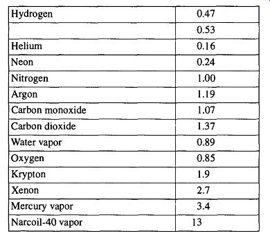
Table 13 Thermionic Ionization Gauge Sensitivity/' Relative to that for
Nitrogen
[True gauge sensitivity is type- and model-specific. Accurate sensitivity tables for your gauge should be supplied by the manufacturer. This table is supplied for reference only.
Reprinted from Vacuum, Vol. 13, H.A. Tasman, A.J.H. Boerboom, and J. Kistemaker, "Vacuum Techniques in Conjunction with Mass Spectrometry," © 1963, p. 43. Elsevier Science Ltd, The Boulevard, Langford Lane, Kidlington OX5 1 GB, UK.]
5.21 Cleaning Hot-Cathode Ion Gauges
The cleaning technique used for hot-cathode ion gauges depends on the shape, structure, and composition of the gauge. Hot-cathode gauges are so sensitive that any cleaning will alter or damage the sensitivity of the gauge. You can minimize gauge damage if the cleaning is performed by electrical heating while the gauge is in a high-vacuum condition. This heat cleaning or baking out can be done by grounding the ion collector and applying a Tesla coil to each of the electrodes within the gauge. Important: Be sure that the controller is off when doing this operation. Otherwise the charge from the Tesla coil may destroy the controller.
Chemical cleaning requires the removal of the gauge from the system and a general (gentle) rinsing with distilled water. If the gauge has a deposit that is blue or silver gray, the contamination is probably tungsten oxide or molybdenum oxide. This deposit can be cleaned as follows:
1. Soak the gauge in a 10-20% sodium carbonate solution. Gently heating the solution to 30°C will accelerate the cleaning process, which should take about 15 minutes.
2. Rinse with copious amounts of water, then let the gauge soak for about a half-hour filled with distilled water. Repeat the distilled water soak two more times.
If the deposit is brown, the offending contamination is probably cracked hydro carbon vapor. This deposit can be cleaned as follows:
1. Soak the gauge in a 10% solution of potassium hydroxide and let it stand for about a half-hour. This soaking may have to be repeated with a fresh potassium hydroxide solution.
2. If there is a discoloration of the electrodes, gently shake some hydrogen peroxide in the gauge until the discoloration disappears.
3. Water spots can be removed with an oxidizer such as any substitute for chromic acid. Do not use chromic acid because it is a toxic waste.
4. Rinse with copious amounts of water, then let the gauge soak for about a half-hour filled with distilled water. Repeat the distilled water soak two more times.
5.22 The Cold-Cathode Ion Gauge
The cold-cathode [a.k.a. Penning gauge, Philips gauge, or PIG (Philips ionization gauge)] requires a high-potential field for removing electrons from the (cold) cathode. This same principle is used in the magnetron and the inverted magnetron.
In the cold-cathode gauge, the center loop is an anode (see Fig. 49) and it is maintained at a very high electrical potential (2-10 kV). The two plates are cathodes and are grounded. Electrons travel from the cathodes to the anode, ionizing molecules on their way. A U- or circular-shaped magnet is placed over the cathodes. The magnetic field formed by the magnets forces the electrons to take a longer route than they otherwise would.* Thus, they come into contact with a greater number of gas molecules and create a greater number of ions.
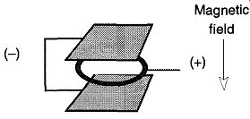
Fig. 49 Basic electrode layout of the Penning gauge. From Fundamentals
of Vacuum Science and Technology, by G. Lewin McGraw-Hill, New York, 1965
(Fig. 5-4).
[At 10^10 torr, it can require 20 minutes for an electron to travel from the cathode to the anode. ]
The range of the cold-cathode gauge is about 10^2 to 10^10 torr. Initiating the discharge within the cold-cathode gauge at lower vacuum ranges (>10^6 torr) is typically fast, within seconds. However, at lower pressures (10^8 to 10^10 torr) it can take hours for the discharge to begin. You may wish to start your cold-cathode gauge at higher pressures and leave it on as the pressure drops to maintain the discharge.
The cold-cathode gauge can act like a sputtering ion pump just as the hot-cathode gauge. However, it can pump nitrogen 10-100 times faster than a hot-cathode gauge. A cold-cathode gauge can pump nitrogen at rates of 0.1-0.5 liters/Section
Thus, if the connection tube to the gauge is too small in diameter, the gauge will remove the nitrogen from the area of the gauge faster than the system can equilibrate. The gauge will then read a greater vacuum than actually exists within the system.
Like a hot-cathode gauge, the cold-cathode gauge can be maintained longer between cleanings if a cold trap is placed between the gauge and the system. However, the gauge will indicate pressures lower than really exist within your sys tem due to the cryogenic pumping capabilities of the cold trap. In addition, it will also slow the speed required for the system and the gauge to come to equilibrium.
When installing the gauge, do not position the opening of the gauge to face the cold trap because momentary warming of the trap will cause evaporating frozen material to contaminate the gauge. When mounting the gauge on a vacuum sys tem, be sure to angle the gauge so that the opening faces down. This angling will prevent particulate matter from falling into the gauge.
Do not leave the gauge on for extended periods of time, especially when the pressure is only about 10^2 torr. Otherwise the gauge can contaminate quickly.
Likewise, do not let the gauge run continuously while the system is roughing down. Brief use will limit the effects of the pumping action of the gauge.
5.23 Cleaning Cold-Cathode Ion Gauges
Some cold-cathode gauges can be taken apart. If you have one of these gauges, it is possible to carefully sand any surface contamination off the grid with a fine grade glass-sanding paper (do not use a metal file that could leave metal filings within the gauge. These filings can cause major problems during use). The gauge should then be rinsed with appropriate solvents followed by rinses of distilled water and then methanol. After the gauge is reassembled, be prepared to realign the magnet (follow the manufacturer's guidelines).
If your gauge is glass-bodied, it cannot be taken apart and you are limited to the chemical cleaning processes mentioned for the hot-cathode ion gauge.
5.24 The Momentum Transfer Gauge (MTG)
The momentum transfer gauge (MTG) was first developed as a lab curiosity in 1962. It uses the principle of gas viscosity to slow a spinning ball bearing that is levitated by magnetism. The levitated ball is rotated at speeds of up to 100,000 rps and then allowed to coast. The only mechanism used to slow down the ball is the friction of air on its surface. The less air in the system, the less friction on the ball.
Currently, MTGs read the vacuum ranges 10^2 to 10^8 torr and, with modern electronics, have demonstrated remarkable accuracy and sensitivity (±1% accuracy in the 10^2 - to 10^5 -torr range).
Because the MTG neither heats nor ionizes the gases within a vacuum system, it is unique in the inferred gauge category. By not altering or changing the composition of the gases within a closed system, it offers special opportunities. However, MTGs require extensive and expensive electronic controls, measuring equipment, and special vibrationless platforms. Thus, very few research labs have the needs that can justify the expense and demands of these gauges.
(cont. to part 3)