AMAZON multi-meters discounts AMAZON oscilloscope discounts
Directional couplers are devices that will pass signal across one path while passing a much smaller signal along another path. One of the most common uses of the directional coupler is to sample a RF power signal either for controlling transmitter out put power level or for measurement. An example of the latter use is to connect a digital frequency counter to the low-level port and the transmitter and antenna to the straight-through (high-power) ports.
The circuit symbol for a directional coupler is shown in Fig. 1. Note that there are three outputs and one input. The IN-OUT path is low-loss and is the principal path between the signal source and the load. The coupled output is a sample of the forward path while the isolated showed very low signal. If the IN and OUT are reversed then the roles of the coupled and isolated ports also reversed.
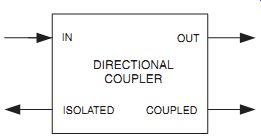
FIG. 1
Directional coupler
circuit symbol
An implementation of this circuit using transmission line segments is shown in Fig. 2. Each transmission line segment (TL1 and TL2) has a characteristic impedance, Zo, and is a quarter-wavelength long. The path from port 1 to port 2 is the low loss signal direction. If power flows in this direction, then port 3 is the coupled port and port 4 is isolated. If the power flow direction reverses (port 2 to port 1) then the respective roles of port 3 and port 4 are reversed.
For a coupling ratio (port 3/port 4) < -15 dB the value of coupling capacitance must be:

(Eqn. 1) The coupling ratio is:

(Eqn. 2) where The bandwidth is about 12%.
__ 2uF.
C.R. _ 20 log 1_ CZo21in decibels2 Cc 6 0.18
_ Zo 1in farads2.
253
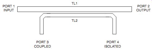
FIG. 2 Transmission line directional coupler.
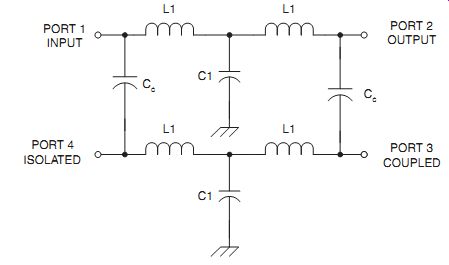
FIG. 3 L-C version of directional coupler.
The circuit shown in Fig. 3 is an LC lumped constant version of the transmission lines. This network can be used to replace TL1 and TL2 in Fig. 2. The values of the components are:
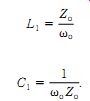
(Eqn. 3) and (Eqn. 4)
Figure 11-4 shows a directional coupler used in a lot of RF power meters and VSWR meters. The transmission lines are implemented as printed circuit board tracks. It consists of a main transmission line (TL1) between Ports 1 and 2 (the low loss path) and a coupled line (TL2) to form the coupled and isolated ports. The coupling capacitance (in picofarads) is approximated by 9.399X (X is in meters) when implemented on G-10 Epoxy fiberglass printed circuit board.
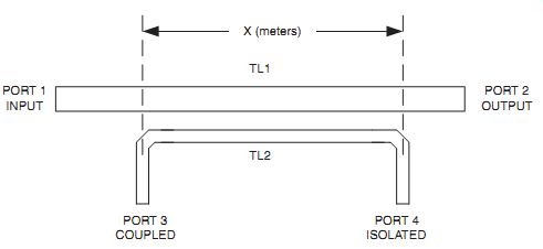
FIG. 4 Transmission line directional coupler.
A reflectometer directional coupler is shown in Fig. 5A. This type of directional coupler is at the heart of many commercial VSWR meters and RF power meters used in the HF through low-VHF regions of the spectrum. This circuit is conceptually similar to the previous transmission line but is designed around a toroid transmission line transformer. It consists of a transformer in which the low-loss path is a single-turn primary winding and a secondary wound of enameled wire.
Details of the pick-up sensor are shown in Fig. 5B. The secondary is wound around the rim of the toroid in the normal manner, occupying not more than 330_ of circumference. A rubber or plastic grommet is fitted into the center hole of the toroid core. The single-turn primary is formed by a single conductor passed once through the hole in the center of the grommet. It turns out the 3/16" o.d. brass tubing (the kind sold in hobby shops that cater to model builders) will fit through several standard grommet sizes nicely and will slip-fit over the center conductor of SO-239 coaxial connectors.
Another transmission line directional coupler is shown in Fig. 6. Two short lengths of RG-58/U transmission line (~ 6") are passed through a pair of toroid coils.
Each coil is wound with 8 to 12 turns of wire. Note that the shields of the two trans mission line segments are grounded only at one end.
Each combination of transmission line and toroid core form a transformer similar to the previous case. These two transformers are cross-coupled to form the net work shown. The XMTR-ANTENNA path is the low-loss path, while (with the signal flow direction shown) the other two coupled ports are for forward and reflected power samples. These samples can be rectified and used to indicate the relative power levels flowing in the forward and reverse directions. Taken together these indications allow us to calculate VSWR.
Directional couplers are used for RF power sampling in measurement and transmitter control. They can also be used in receivers between the mixer or RF amplifier and the antenna input circuit. This arrangement can prevent the flow of LO signal and mixer products back toward the antenna where they could be radiated and cause electromagnetic interference (EMI) to other devices.
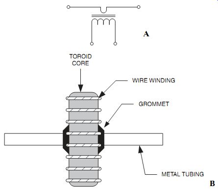
FIG. 5 (A) Directional coupler suitable for use in an RF power meter; (B)
Physical implementation.
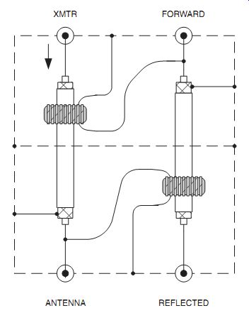
FIG. 6 Dual transmission line directional coupler.
Conclusion
The passive diplexers and directional couplers discussed in this article are the mainstays of many electronic circuits used at higher frequencies.
References:
ARRL Handbook for Radio Amateurs CD-ROM Version 1.0 (1996). Newington, CT: ARRL.
Carr, J. J. (1998). Practical Antenna Handbook 3rd Edition. New York: McGraw Hill.
Carr, J. J. (1997). Microwave and Wireless Communications Technology. Boston: Newnes.
Carr, J. J. (1996). Secrets of RF Circuit Design 2nd Edition. New York: McGraw Hill.
Hagen, J. B. (1996). Radio-Frequency Electronics: Circuits and Applications. Cambridge ( UK): Cambridge Univ. Press.
Hardy, J. (1979). High Frequency Circuit Design. Reston, VA: Reston (Division of Prentice-Hall).
Kinley, R. H. (1985). Standard Radio Communications Manual: With Instru mentation and Testing Techniques. Englewood Cliffs, NJ: Prentice-Hall.
Laverghetta, T. S. (1984). Practical Microwaves. Indianapolis, IN: Howard W. Sams.
Liao, S. Y. (1990). Microwave Devices & Circuits. Englewood Cliffs, NJ: Prentice Hall.
Sabin, W. E., and Schoenike, E. O. (Eds.) (1998). HF Radio Systems & Circuits 2nd Edition. Atlanta: Noble.
Shrader, R. L. (1975). Electronic Communication 3rd Edition. New York: McGraw-Hill.
Vizmuller, P. (1995). RF Design Guide. Boston/London: Artech House.