AMAZON multi-meters discounts AMAZON oscilloscope discounts
The hybrid coupler (Fig. 1) is an AF or RF device that will either (a) split a signal source into two directions or (b) combine two signal sources into a common path.
The circuit symbol shown in Fig. 1 is essentially a signal path schematic. Consider the situation where an RF signal is applied to port 1. This signal is divided equally, flowing to both ports 2 and 3.
Because the power is divided equally the hybrid is called a 3-dB divider, i.e., the power level at each adjacent port is one-half (- 3 dB) of the power applied to the in put port.
If the ports are properly terminated in the system impedance then all power is absorbed in the loads connected to the ports adjacent to the injection port. None travels to the opposite port. The termination of the opposite port is required, but it does not dissipate power because the power level is zero.
The one general rule to remember about hybrids is that opposite ports cancel.
That is, power applied to one port in a properly terminated hybrid will not appear at the opposite port. In the case cited above, the power was applied to port 1 so no power appeared at port 4.
One of the incredibly useful features of the hybrid is that it accomplishes this task while allowing all devices connected to it to see the system impedance, Ro. For example, if the output impedance of the signal source connected to port 1 is 50-ohm , the loads of ports and port 3 are 50-ohm , and the dummy load attached to port 4 is 50-ohm then all devices are either looking into, or driven by, the 50-ohm system impedance.
One source of reasonably priced hybrid devices is Mini-Circuits Laboratories ( 13 Neptune Avenue, Brooklyn, NY, 11235, USA. Web site: minicircuits.com).
They have a large selection of 0 deg, 90 degree , and 180 deg. hybrid combiners and splitters.
Applications of hybrids
The hybrid can be used for a variety of applications where either combining or splitting signals is required.
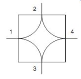
FIG. 1 Symbol for hybrid.
Combining signal sources
In Fig. 2 there are two signal generators connected to opposite ports of a hybrid (ports 2 and 3). Power at port 2 from signal generator 1 is therefore canceled at port 3, and power from signal generator 2 (port 3) is canceled at port 2. Therefore, the signals from the two signal generators will not interfere with each other.
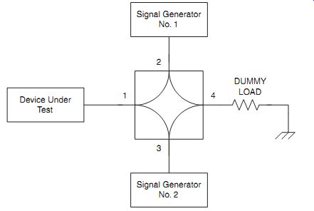
FIG. 2 Combining two signal sources.
In both cases, the power splits two ways. For example, the power from signal generator 1 flows into port 2 and splits two ways. Half of it (3 dB) flows from port 2 to port 1 while the other half flows from port 2 to port 4. Similarly with the power from signal generator 2 applied to port 3. It splits into two equal portions, with one flowing to port 1 and the device under test and half flowing to the dummy load.
Bidirectional amplifiers
A number of different applications exists for bidirectional amplifiers, i.e., amplifiers that can handle signals from two opposing directions on a single line. The telecommunications industry, for example, uses such systems to send full duplex signals over the same lines.
Similarly, cable TV systems that use two-way (e.g., cable MODEM) require two way amplifiers. Figure 12-3 shows how the hybrid coupler can be used to make such an amplifier. In some telecommunications textbooks the two directions are called "east" and "west", so this amplifier is occasionally called an east-west (E-W) amplifier. At other times this circuit is called a repeater.
In the bidirectional E-W amplifier of Fig. 3, amplifier A1 amplifies the signals traveling west to east while A2 amplifies signals traveling east to west. In each case, the amplifiers are connected to hybrids HB1 and HB2 via opposite ports so will not interfere with each other. Otherwise, connecting two amplifiers input-to-output-to-input to-output is a recipe for disaster-if only a large amount of destructive feedback.
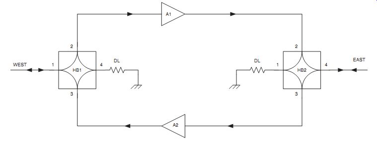
FIG. 3 Bidirectional "repeater'' amplifier.
Transmitter/receiver isolation
One of the problems that exists when using a transmitter and receiver together on the same antenna is isolating the receiver input from the transmitter input. Even a weak transmitter will burn out the receiver input if its power were allowed to reach the receiver input circuits. One solution is to use one form of transmit/receive (T/R) relay. But that solution relies on an electromechanical device, which adds problems of its own (not the least of which is reliability).
A solution to the T/R problem using a hybrid is shown in Fig. 4. In this circuit the transmitter output and receiver input are connected to opposite ports of a hybrid device. Thus, the transmitter power does not reach the receiver input.
The antenna is connected to the adjacent port between the transmitter port and the receiver port. Signal from the antenna will flow over the path from port 1 to port 2 to reach the receiver input. Transmitter power, on the other hand, enters at port 3 and is split into two equal portions. Half the power flows to the antenna from port 3 to port 1 while the other half flows to a dummy load from port 3 to port 4.
There is a problem with this configuration. Because half the power is routed to a dummy load, there is a 3-dB reduction in the power available to the antenna. A solution is shown in Fig. 5. In this configuration a second antenna is connected in place of the dummy load. Depending on the spacing (S), and the phasing, various directivity patterns can be created using two identical antennas.
If the hybrid produces no phase shift of its own then the relative phase shift of the signals exciting the antennas is determined by the length of the transmission line between the hybrid and that antenna. A 0 deg. phase shift is created when both trans mission lines are the same length. Making one transmission line a half-wavelength longer than the other results in a 180 deg. phase shift. These two relative phase relationships are the basis for two popular configurations of phased array antenna. Consult an antenna book for other options.
Phase-shifted hybrids
The hybrids discussed thus far split the power half to each adjacent port but the signals at those ports are in-phase with each other. That is, there is a 0_ phase shift over the paths from the input to the two output ports. There are, however, two forms of phase-shifted hybrids. The form shown in Fig. 6A is a 0 deg. -180 deg. hybrid. The signal over the path from port 1 to port 2 is not phase-shifted (0 deg.) while that between port 1 and port 3 is phase-shifted 180_. Most transformer based hybrids are inherently 0 deg. -180deg. hybrids.
A 0_-90 degree hybrid is shown in Fig. 6B. This hybrid shows a 90 degree phase shift over the port 1/port 2 path and a 0 deg. phase shift over the port 1/port 3 path. This type of hybrid is also called a quadrature hybrid.
One application for the quadrature hybrid is the balanced amplifier shown in Fig. 7. Two amplifiers, A1 and A2, are used to process the same input signal arriving via hybrid HB1. The signal splits in HB1 and so becomes the inputs to both A1 and A2. If the input impedances the amplifiers are not matched to the system impedance then signal will be reflected from the inputs back toward HB1. The reflected signal from A2 arrives back at the input in-phase (0 deg.) but that reflected from A1 has to pass through the 90 degree phase shift arm twice and so has a total phase shift of 180 deg. Thus, the reflections caused by mismatching the amplifier inputs are cancelled out.
The output signals of A1 and A2 are combined in hybrid HB2. The phase balance is restored by the fact that the output of A1 passes through the 0_ leg of HB2, while the output of A2 passes through the 90 degree leg. Thus, both signals have undergone a 90 degree phase shift, so are now restored to the in-phase condition.
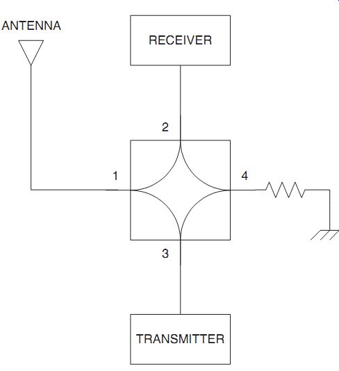
FIG. 4 Use of hybrid as a T/R switch.
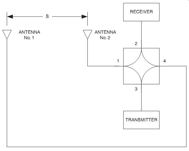
FIG. 5 Combining two antennas in T/R switch.
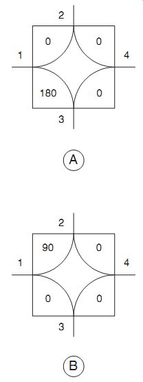
FIG. 6 (A) 180 degree hybrid; (B) 90 degree hybrid.
Use with receive antennas Examples given above combine a receiver and transmitter on a single antenna or antenna system. It is also possible to use the hybrid for antenna arrays intended for receivers. Antenna spaced some distance X apart will have different patterns and gains depending on the value of X and the relative phase of the currents in the two antennas. One can, therefore, connect the antennas to ports 2 and 3 and the receiver antenna input to port 1. A terminating resistor would be used at port 4. You can use 0_, 90 degree , or 180 deg. hybrids depending on the particular antenna system.
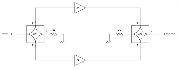
FIG. 7 Balanced amplifier.
Conclusion
The hybrid coupler-combiner splitter is a remarkably useful passive RF component that will solve a lot of practical problems.
References
Carr, J. J. (1998). Practical Antenna Handbook 3rd Edition. New York: McGraw Hill.
Carr, J. J. (1997). Microwave and Wireless Communications Technology. Boston: Newnes.
Carr, J. J. (1996). Secrets of RF Circuit Design 2nd Edition. New York: McGraw Hill.
Hagen, J. B. (1996). Radio-Frequency Electronics: Circuits and Applications. Cambridge ( UK): Cambridge Univ. Press.
Hardy, J. (1979). High Frequency Circuit Design. Reston, VA: Reston (Division of Prentice-Hall).
Kinley, R. H. (1985). Standard Radio Communications Manual: With Instru mentation and Testing Techniques. Englewood Cliffs, NJ: Prentice-Hall.
Laverghetta, T. S. (1984). Practical Microwaves. Indianapolis, IN: Howard W. Sams.
Liao, S. Y. (1990). Microwave Devices & Circuits. Englewood Cliffs, NJ: Prentice Hall.
Sabin, W. E., and Schoenike, E. O. (Eds.) (1998). HF Radio Systems & Circuits 2nd Edition. Atlanta: Noble.
Shrader, R. L. (1975). Electronic Communication 3rd Edition. New York: McGraw-Hill.
Vizmuller, P. (1995). RF Design Guide. Boston/London: Artech House.