AMAZON multi-meters discounts AMAZON oscilloscope discounts
AM-band, shortwave, and VHF monitor receivers often produce output signals that are a terrible mess of weird squawks, squeals, and other assorted objectionable noises. Shortwave receivers in particular show a lot of weird signals, but the growing number of local electronic products are making the cacophony louder and messier than ever before. Fortunately, many of the interference problems that you'll see on your receiver can be fixed or at least reduced significantly in severity. Interference problems fit into two major categories: unwanted local radio station signals and unwanted radiation from other electronic devices.
Radio station interference
Signals from AM, FM, and TV stations are quite powerful, so they can produce a number of problems for receiver owners in their immediate vicinity. Unfortunately, in many areas of the country, residences are located quite close to these types of stations (in a few areas, even shortwave stations are located near homes).
Typical problems from local transmitters include blanketing, desensitization, harmonic generation, and intermodulation. Let's look at each of these in turn.
Blanketing
The blanketing problem occurs when a very strong local signal completely washes out radio reception all across the band. It generally affects the band that the signal is found in, but not other bands. The offending signal can be heard all across the band or at numerous discrete points.
Desensitization
The desensitization problem is a severely reduced receiver sensitivity caused by the presence of a strong local signal. Desensitization can occur across a wide frequency spectrum, not only in the band where the offending signal is located. The strong offending signal might not be heard, except when the receiver is tuned to or near its frequency.
Harmonic generation
If the signal is strong enough to drive the RF amplifier of the receiver into non linearity then it might generate harmonics (integer multiples) of the strong signal.
For example, if you live close to a 780-kHz AM broadcast band signal and the receiver overloads from that signal then you might be able to pick up the signal at 2f (1560 kHz), 3f (2340 kHz), 4f (3120 kHz), and so on up throughout the shortwave bands. Notice that this problem is not the fault of the radio station (which must be essentially clean of harmonics because of FCC regulations) but rather is an inappropriate response on the part of your receiver.
Intermodulation
This problem occurs when two signals of different frequencies (for example, F1 and F2) mix together in a nonlinear element to produce a third frequency (F3). The third signal is sometimes called a phantom signal. The frequencies involved might be (and probably are) the assigned fundamental frequency of a legitimate station or their harmonics. The nonlinearity can be caused by receiver overload, improper receiver design, or some other source (legend has it that rusted downspouts and corroded antenna connections can serve as a nonlinear PN junction). As they say in the new science of Chaos Theory, ". . . nonlinearity can arise throughout nature in subtle ways."
The possible new frequency (F3) will be found from F3 _ mF1 _ nF2, where m and n are integers, although not all possibilities are likely to occur in any given situation. Suppose one local ham is operating on 10,120 kHz (in the new 30-m band) and another is operating on 21,390 kHz (in the 15-m band). Both stations are operating normally, but at least one is close enough to overload your receiver and pro duce nonlinearity in the RF amplifier. When the second harmonic of 10,120 kHz (i.e., 20,240 kHz) combines with 21,390 kHz, the result is a third frequency at 21,390 kHz _ 20,240 kHz _ 1,150 kHz-right in the middle of the AM broadcast band.
With all of the signals that might exist in your locality, an extremely large number of possible "intermod" combinations can arise. A hill in my hometown is right in the middle of a densely populated residential neighborhood. On that hill are two 50-kW FM broadcast stations; a 5-kW AM broadcast station; scores of VHF and UHF landmobile radio base stations or repeater transmitters; and an assortment of paging systems, ham operators, medical telemetry systems, and the microwave towers of an AT&T long-lines relay station-all within a city block or two. Only a few radio receivers work well unassisted in that neighborhood!
There are two approaches to overcoming these problems. First, either reject or somehow selectively attenuate the offending signal (or one of the signals, in the case of an intermod problem). This is done using a wavetrap. Second, add a passive pre selector to the front end of the radio receiver between the antenna line and the antenna input of the receiver.
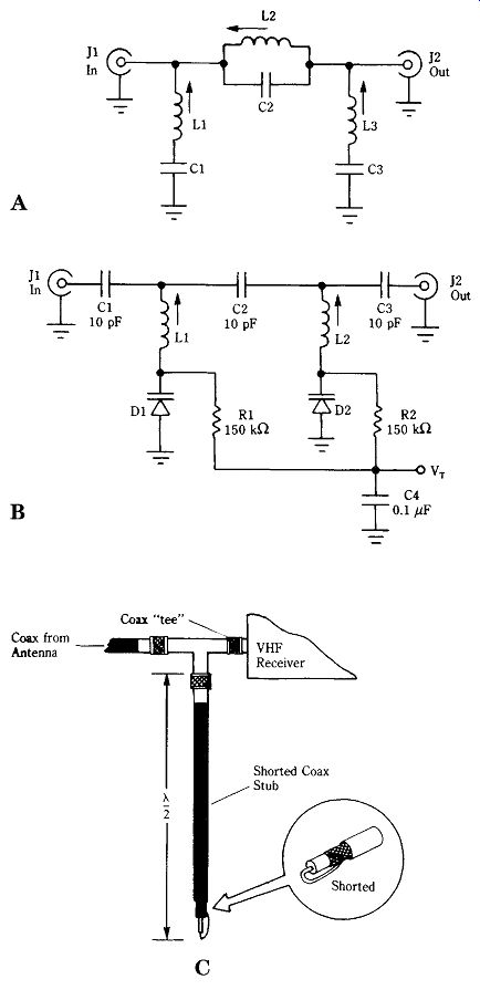
FIG. 1 (A) Series-parallel wave trap, (B) voltage tunable filter/trap,
and (C) VHF/UHF half-wave shorted stub trap.
Figure 1 shows three wavetrap circuits that can be used from the AM band up through VHF/UHF frequencies. The circuit in Fig. 1A is an LC wavetrap based on inductors and capacitors. Two LC resonant circuits are shown in Fig. 1A. In series with the signal path is a parallel resonant circuit (L2/C2). These circuits have a very high impedance at the resonant frequency so they will attenuate signals of that frequency trying to pass through the line between J1 and J2. At the same time, the impedance at all other frequencies is high, so those frequencies will pass easily from J1 to J2. Shunted across the line on both ends of the signal path are a pair of series resonant circuits. These LC circuits have a low impedance at the resonant frequency and a high impedance at all other frequencies so they will shunt only the offending signals to ground.
The wavetrap of Fig. 1A can be built using either fixed inductors and variable capacitors or vice versa. It can be built either for one fixed frequency or as a variable wavetrap that can be tuned from a front-panel knob to attenuate the offending signal.
Figure 1B shows the circuit of a similar type of wavetrap, but it is built with voltage-variable capacitance diodes, also called varactors. These diodes produce a capacitance across their terminals that is proportional to the applied reverse bias tuning voltage (VT). In the circuit of Fig. 1B, only series resonant circuits are used.
Wavetraps built from LC circuit elements are useful well into the VHF region. In fact, many video and other electronics stores sell wavetraps. (Fig. 1A) built especially for the FM broadcast band (88 to 108 MHz) because nearby FM broad casting stations are frequent sources of interference to VHF television receivers.
Another VHF/UHF wavetrap is shown in Fig. 1C. This type of wavetrap is called a half-wavelength shorted stub. One of the properties of a transmission line is that it will reflect the load impedance every half-wavelength along the line. When the end of the stub is shorted, therefore, a "virtual" short-circuit will also appear every half-wavelength along the line. This length is frequency-sensitive so the physical length of the line is a tuning factor for this wavetrap.
The length of the line is found from Lft _ 492 V/FMHz, where L is in feet and F is in megahertz. The V term is the velocity factor of the transmission line. For common coaxial lines, the value of V ranges from 0.66 (polyethylene) to 0.82 (polyfoam). For example, assume that you need to eliminate the signal from a local FM broadcaster on 88.5 MHz. The shorted stub is made from ordinary coax (V _ 0.66) and must have a length of [(492)(0.66)/88.5] _ 3.669 ft (or 44_).
The half-wavelength shorted stub is connected in parallel with the antenna in put on the receiver. In the case shown in Fig. 1C, the stub is connected to the receiver and antenna transmission line through a coaxial "tee" connector. Although UHF connectors are shown, the actual connector that you would select must match your receiver and antenna. Also, it is possible to use 300-ohm twinlead transmission line, rather than coax, as long as that type of line is used on the receiver and antenna.
The other approach to solving the problem is to use a passive preselector ahead of the receiver. Again, the preselector is inserted directly in the transmission line between the receiver antenna input connector and the antenna transmission line.
Figure 2 shows a typical circuit for this type of preselector. The tuning is controlled by C1A/L2 and C1B/L3 and are trimmed by C2 and C3 to permit tracking of the two LC circuits. The circuit should be built in a closed, shielded metal box.
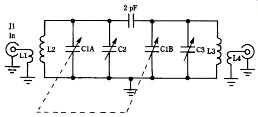
FIG. 2 Passive tunable preselector circuit.
Other interference
The world is a terrible place for sensitive radio receivers: a lot of pure crud (other than the programming material!) comes over the airwaves from a large variety of electrical and electronic devices. There are also some renegade transmitters out there. For example, in the HF shortwave spectrum, you will occasionally hear a "beka-beka-beka" pulsed signal that seems to hop around quite a bit. It will set down on your favorite listening frequency and then go to another. Unfortunately, the nature of a pulsed signal is to spread out over several megahertz-wiping out large segments of the spectrum. That signal is an over-the-horizon backscatter (OTHB) radar in the USSR called by North American SWLs and hams the "Russian Woodpecker." That's one that we can do little about, unfortunately, so let's look at some interfering signals that we can affect.
Light dimmers
A lot of homes are equipped with dimmers instead of switches to control the lighting. These devices are based on silicon-controlled rectifiers (SCRs) that cut the ac sine wave off over part of its cycle, producing a harmonic-rich sharp waveform.
These devices can produce a sound described as "frying eggs" well into the short wave spectrum. Diagnosis is simple: turn off the light. If the noise stops when the light is turned off, then the dimmer is at fault. Although it is possible to install LC line noise filters at the dimmer, that approach is not usually feasible. It would be better to (a) remove the dimmer and replace it with an on/off switch, (b) replace the dimmer with a special model that is designed to suppress radio noise, or (c) keep the light turned off when using the receiver.
Videocassette recorders (VCR)
The VCR is a magnificent entertainment product, and I own one. But I also own SWL and ham radio receivers, and I can always tell when a popular movie is on TV.
Because lots of people videotape the movie (legalities notwithstanding), their VCRs are in operation for a couple of hours at a time. The VCR contains a number of radiation-producing circuits, including a 3.58-MHz color subcarrier oscillator. On popular TV nights, I can hear a load of trash around that frequency, which is right in the middle of the 80-m amateur radio band.
TV receivers The TV set in your home contains at least two major interference producers: the 60-Hz vertical deflection system and the 15,734-kHz horizontal deflection system.
The horizontal system includes a high-powered amplifier driving a high-voltage "fly back" transformer and a deflection yoke. As you tune up and down the shortwave band, you will hear "birdies" of the horizontal deflection signal every 15,734 kHz; these are the harmonic signals of the TV horizontal signal.
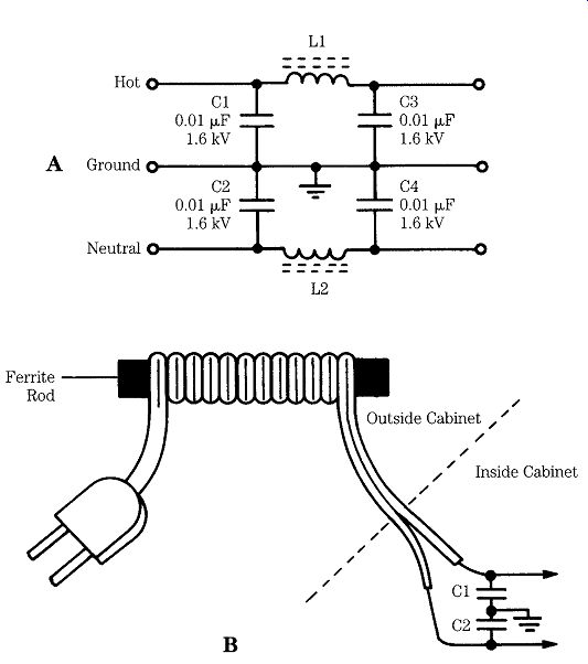
FIG. 3 (A) AC line EMI filter and (B) power cord on ferrite rod also reduces
EMI by acting as a RF choke.
One quick solution to many interference problems from VCRs and TVs is the line-noise filters shown in Fig. 3. These "EMI filters" are placed in the power line coming from the offending device. It works much of the time because the principal source of the noise signal is radiation from the power line of the VCR or TV. The EMI filter should be installed as close as possible to the body of the offending device.
The filter in Fig. 3A uses LC elements to form a low-pass filter network that is placed in series with the ac power line. Homebrew filters should be built inside of a quality, heavy-duty, shielded metal box. If you make your own filter, be sure to use capacitors and inductors that are rated for continuous use across ac power lines.
Most readers should consider buying a ready-made LC line filter from a distributor (even RadioShack offers models suitable for most applications). Homebrew EMI filters have a potential for danger if built incorrectly-they can electrocute you or cause a fire in your house!
The filter shown in Fig. 3B can be made for any appliance that uses ordinary zipcord for the power line. The cord is wrapped around a 3/8" to 1/2" ferrite rod (Amidon Associates), which is then taped to keep it in place. This filter should be mounted as close as possible to the TV or VCR chassis. The optional bypass capacitors (C1 and C2) inside the equipment cabinet should be 0.01-uF 1600-WVdc disk ceramics that are rated for continuous ac service.
Microwave ovens
Most American homes are equipped with microwave ovens. These devices use a magnetron tube to produce several hundred watts of microwave power on a frequency of approximately 2450 MHz. The high voltage applied to the "maggie" is typically pulsating dc [i.e., it is rectified ac, but not ripple-filtered (as are true dc power supplies)]. This pulsating dc causes "hash" in radio receivers. Although better quality microwave ovens are equipped with EMI filters, many are not. However, most manufacturers or servicers of microwave ovens can install EMI filters inside the oven. Alternatively, one of the EMI filters shown in Fig. 3 can be used.
Personal computer noise The proliferation of personal computers has greatly increased the amount of noise in the radio spectrum. The noise is caused by the internal circuits that operate using digital clock pulses. Older machines, which use internal clock frequencies of 1 to 4.77 MHz (original IBM PC), wipe out large portions of the AM and shortwave bands. If you doubt this, try using an AM radio near the computer! Later computers (XT-turbo and AT-class machines) used higher clock frequencies (e.g., 8, 10, 12, 16, 25, or 33 MHz) and these can wipe out the VHF bands as well-including the FM broadcast band. I've noticed that the XT-turbo machine that I use for word-processing my technical articles and books wipes out the AM band in the regular mode and the FM band in the turbo mode-but the turbo mode produces little interference on AM (a result of the higher clock frequency, I suspect).
Most of the noise produced by the computer is radiated from the power line or from the keyboard cable. In the latter case, be sure that a shielded keyboard cable is used. The power line noise is often susceptible to the same kinds of EMI filters.
Another source of noise is the printer (or more commonly, the printer cable). If the cable between the computer and the printer is unshielded then replace it with a shielded type. Otherwise, you might want to consider a ferrite clamp-on filter bar, such as the Amidon 2X-43 or equivalent.
Cable TV noise
Many communities today are wired for cable TV. These systems transmit a large number of TV and FM broadcast and special-service signals along a coaxial trans mission line. They operate on frequencies of 54 to 300 MHz in 36-channel systems and 54 to 440 MHz in the 55-channel systems. Whenever a large number of signals get together in one system, intermodulation is a possibility-and that means signals outside of the official spectrum.
The problem is that signals leak out of the cable TV system and interfere with your receiver. The only thing that you can do legally is to complain to the cable operator and insist he or she eliminate the interference. Fortunately, the FCC is your ally: by law, the operator must keep the signals home! EMI interference to shortwave and monitor receivers is terribly annoying and sometimes gets so bad that it wipes out reception altogether. Some of these "fixes" might well eliminate the problem and make your radio hobby a lot more fun.