AMAZON multi-meters discounts AMAZON oscilloscope discounts
Electronic pollution is all around us. Radio and noise waves impinge us all of the time. Never has electromagnetic interference (EMI) been so great as it is today. One source defines EMI thusly: ". . . electromagnetic interference is a degradation in performance of an electronic system caused by an electromagnetic disturbance." At worst, EMI can cause a loss of human life, as when it interferes with an aircraft or automobile electronic system. At best, it will pass unnoticed or will interfere with the electronic system on a subaudible basis.
The European Community has issued regulations pertaining to EMI in all manner of electrical and electronic equipment. Electrical and electronic products sold in Europe must exhibit that it neither emits nor is affected by radiation and conduction of EMI. In other words, it must be electromagnetically compatible (EMC).
Means of EMI transmission
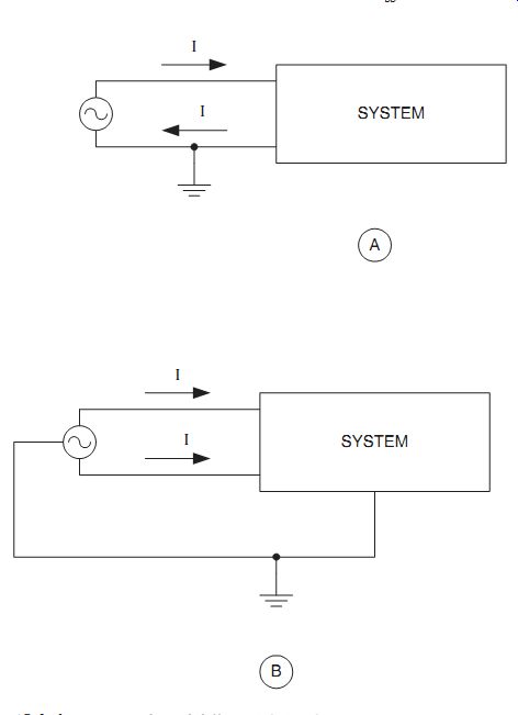
EMI is transmitted from the source to the victim system in two basic ways: conduction and radiation. The difference is that the EMI travels along a wire in conduction and travels by air in radiation. In general (but not always), radiation (Fig. 15-1A) occurs at high frequencies (_30 MHz) and conduction (Fig. 15-1B) occurs at low frequencies (_30 MHz). In some cases, both radiation and conduction can occur. In those cases, either radiation occurs first and then the wave is con ducted into the equipment on a line (Fig. 15-1C) or the radiation occurs after conduction (Fig. 15-1D).
In general, the existence of EMI can occur only if (1) there is a source of energy, (2) there is a receiver of that energy, and (3) there is a transmission path between the two.
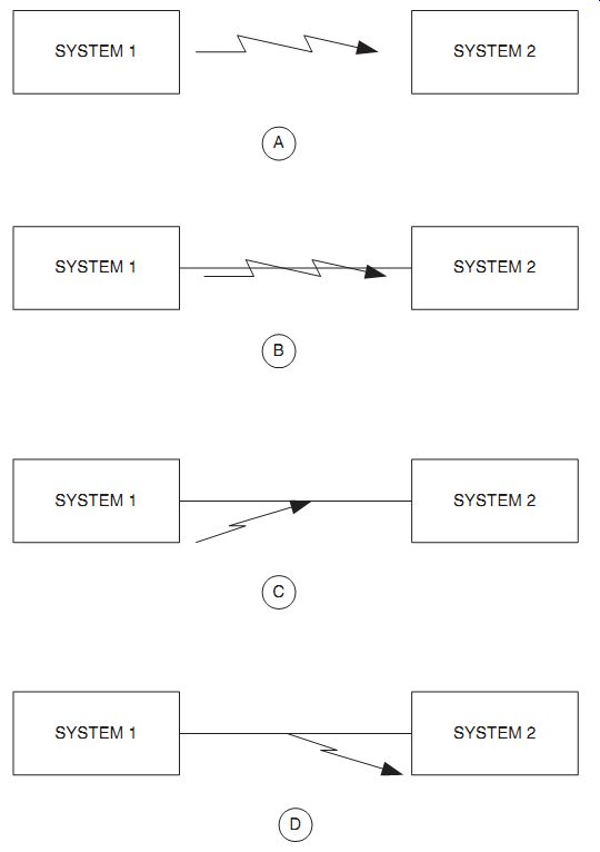
15-1 (A) Radiation, (B) conduction, (C) conduction from radiation, and (D)
radiation from conduction.
If any of the three do not exist, EMI cannot occur. What we do about EMI depends on the situation. For example, in the case of some noise sources we can turn it off or otherwise suppress it. Otherwise, we might have to live with the effects of EMI as best we can.
Electronic noise--Noise comes in two different types: continuous and transient. By definition, noise has been standardized as "transient" if it lasts less than 1/60th of a second (16.67 ms) and continuous if it is of longer duration.
Continuous noise
The low-frequency noise sources include fluorescent lights, electric motors, and switching-mode dc power supplies. High-frequency noise is mostly radio frequency interference (RFI), and it can originate in radio transmitters, computer clocks, or other sources.
In the typical RFI environment, signals levels can be between a few microvolts/ meter (_V/m) and 300 V/m. While the latter field strengths are only found close to transmitting antennas for high-power radio and radar stations, anything in excess of 1 V/m can cause damage to unprotected circuits. The test specifications for commercial systems may call for protection to 10 V/m, while automotive and medical environments can call for up to 200 V/m and military environments up to 300-400 V/m.
Analog circuitry tends to be more influenced by RFI than digital circuits because they can be interfered with by lower-voltage fields.
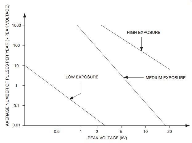
15-2 Average lightning strikes against U.S. power systems.
Transient noise
A "transient" is any temporary (_16.6 ms) overvoltage or overpower condition.
Transients are either repeatable or random in nature. An example of the repeatable type of transient is the discharge of an inductor or capacitor. Examples of random type transients include electrostatic discharge (ESD), lightning, and the nuclear electromagnetic pulse. In the case of lightning, Fig. 15-2 shows the exposure of the U.S. electrical power system to lightning strikes. Clearly, high-voltage lines are struck more frequently than low-voltage lines. Unfortunately, that exposure transmits along the lines to your home or business to disrupt electronic circuits. In fact, the lightning doesn't have to actually strike the line but by induction can cause disruptive currents to flow in the power system by striking something close!
Counters to EMI
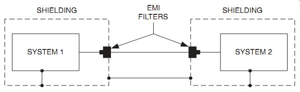
There are two effective ways to counter EMI: shielding and filtering (Fig. 15-3). The shielding is used to guard against radiation interference, while the filter is used to guard against conduction interference. The filters have the advantage of being bidirectional, so they also prevent interference from flowing out of the system as well as prevent it from flowing in.
15-3 Shielding and EMI filtering are suitable defenses.
15-4 (A) Simple but effective low-frequency shielding and (B) high-frequency
shielding.
Shielding
Shielding is used to attenuate the interfering RF signal before it reaches the protected circuitry. Very frequently, the hidden difference between a higher-priced appliance and a lower-priced offering is in the internal shielding that one gets. For example, consider computer monitors. The principal difference between a high priced model and a cheap model is in the shielding that is provided.
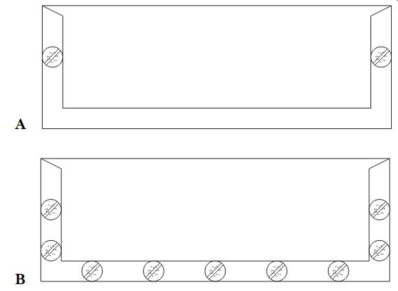
Unfortunately, all shielded enclosures for electronic projects are not created equal. Some enclosures are butt-fitted and have dimples or notches to hold the half shells together. The minimum requirement, as far as I am concerned, for low frequency radiation noise is shown in Fig. 15-4A. Note that the flange of the lower half-shell overlaps the upper half-shell by 4 to 6 mm (at least). There are four screws (two shown) to hold the assembly together. For high frequencies even this box is in sufficient but can be made sufficient by the addition of more screws (Fig. 15-4B).
The rules are that the screws should be not more than a 1/2-wavelength apart and 1/8th-wavelength is better.
Filtering
Filtering can take on different meanings for different situations. In general, most EMI filters are low-pass filters, although high-pass and bandpass filters exist. In some cases of a particular frequency being the cause of interference, a notch filter may be used. In general, a perfect, ideal single component filter (either a capacitor or inductor) has a theoretical roll-off or gain of _20 dB/decade, with a practical maximum of something between _60 and _120 dB. In fact, real components do not achieve that theoretical goal. Capacitors are more useful in high-impedance circuits, whereas inductors are more useful in lower-impedance circuits.
Perhaps the simplest form of single component filter is the feedthrough capacitor (a.k.a. "EMI filter"). When combined with good shielding, the use of such a capacitor can be quite sufficient. Figure 15-5 shows two methods of passing a feedthrough capacitor through a shielded panel. In Fig. 15-5A we see the screw in variety. The threaded nut is cinched tight against the chassis or panel. In Fig. 15-5B we see the installation of a solder-in type of feedthrough capacitor. A small fillet of solder is used to hold the capacitor against the chassis or panel. This type of capacitor assumes a solderable chassis or panel, thus it eliminates the use of aluminum.
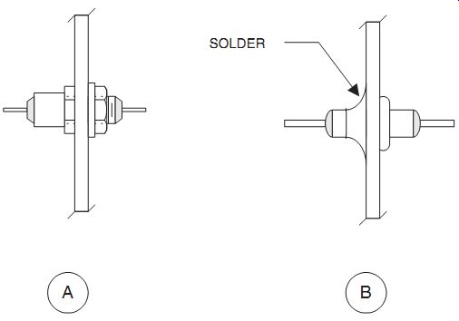
15-5 Two types of feedthrough capacitor.
Where greater suppression is needed, a combination of L and C elements is needed. A two-component L- section filter is shown in Fig. 15-6A. This filter produces a theoretical gain of _40 dB/decade, which means 100:1 per decade between input and output signals. This filter can be used at any frequency, although the values will tend to differ between, say, LF and VHF. The ideal is to keep the lead lengths as short as possible to prevent radiation of the signal. As an alternative, a higher-order filter can be realized by replacing the grommet in Fig. 15-6A with a second feedthrough capacitor. In that case, a theoretical gain of _60 dB/decade is realized.
In Fig. 15-6B we see a case where the opposite situation occurs, i.e., the inductor input L- section filter. In this case the inductor or RF choke is mounted external to the chassis and directly drives the feedthrough capacitor.
Figure 15-7 shows a graphic of which filters to use when the source impedances are known. For example, in the case where the input impedance and the output impedance are both low then use either a single inductor or RF choke or a T-filter consisting of two inductors and a capacitor. When the source impedance is high and the output impedance is low then use a single capacitor input L- section filter. Similarly, when the input impedance is low and the output impedance is high use an inductor input L- section filter. Finally, when the input and output impedances are both high use either a single capacitor or a pi- section filter as shown.
Common mode and differential currents
Noise currents can flow in two modes: differential and common mode. These are defined as follows.
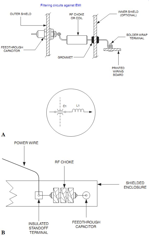
15-6 Simple L- section filters: (A) internal capacitor input type and (B)
external inductor in put type.
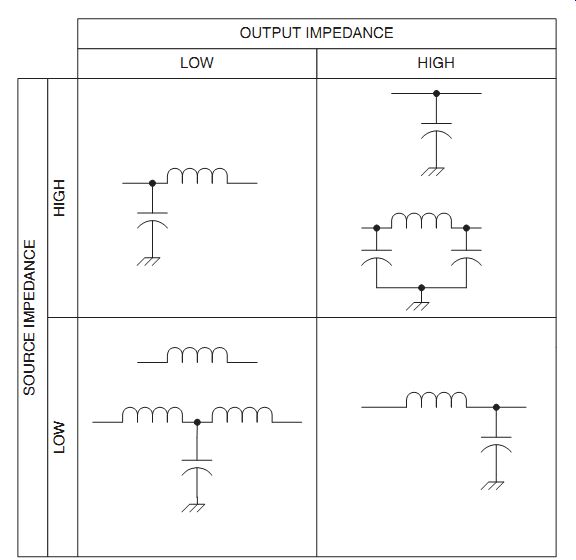
15-7 Several situations and the filters to implement them.
Differential mode
As shown in Fig. 15-8A there is a conducted signal on a signal line that is re turned along the return line or via a grounded connection. The noise current is characterized by the arrows flowing in different directions.
Common mode
In common mode conduction noise appears in multiple conductors flowing in the same direction.
The filtering necessary for differential and common mode filtering is different.
In differential mode filtering it is necessary to place a filter in series with the "hot" lead, with suitable bypassing to ground. In the common mode case the same filtering must be applied to all affected leads. Figure 15-9 shows a filter that is suitable for both differential and common mode forms of EMI.
15-8 Common mode and differential signals.
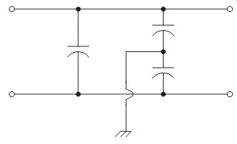
15-9 Filter for both differential and common mode signals.
AC power line filtering
The ac power lines are a source of conducted EMI and must be filtered extensively to make them really clean. Not only should the ac lines be filtered against RFI but also against lightning strikes at a distance. The lightning and other high-voltage transients can be handled per Fig. 15-10 with metal oxide varistors (MOV). These devices are made by various suppliers and can act like a pair of zener diodes back-to back. In other words, they snip the high-voltage transient to a lower level, regardless of polarity. Basically, the way they work is that they act like an insulator at lower volt ages but when a certain critical threshold voltage is exceeded the varistors develop a low resistance, shunting the offending voltage transient to a low value. Varistors are used primarily for transient voltage spikes on the ac power line.
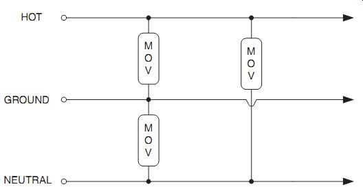
15-10 Metal oxide varistors (MOV) use on AC power mains.
For RFI a filter must be provided to the ac power line. Figure 15-11 shows a suitable filter that affects both common mode and differential RFI on the line. When the values are high enough, it will also protect somewhat against lightning and other transients because those transients have a high-frequency component as well as the fundamental frequency. Suitable filters have been molded into ac power line sockets.
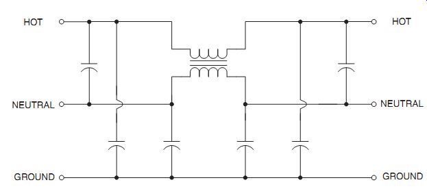
15-11 AC power mains filter.
Special medical EMI problems
EMI problems exist in medical electronic devices such as electrocardiograph (ECG) or electroencephalograph (EEG) machines. These machines have to process signals on the order of a few microvolts (_V) to about 1 millivolt (mV) in the presence of strong interfering signals. In addition to regular RFI problems, there are two additional problems. First, there is the problem of the defibrillator. This is a high voltage (several kilovolts!) capacitive discharge device used to "jump start" the heart of a patient undergoing resuscitation. The second problem is in the application of 500- to 2500-kHz high-powered RF electro-surgery units just a few centimeters from the site of the EEG or ECG electrodes. As much as 400 or 500 W of RF could be applied to the "circuit" only a few centimeters from the pick-up electrodes! Figure 15-12 shows the input to a bioelectric amplifier suitable for EEG or ECG use in the presence of high electrical or electromagnetic fields. Both defibrillator and electro-surgery units can be accommodated by the filtering shown. Both ECG and EEG signals consists of signals below 100 Hz, so an RC filter will suffice in this case.
The RC filter consists of resistors R1 through R6 and capacitors C1 through C4. It is a low-pass filter.
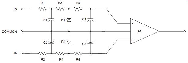
15-12 ECG/EEG preamplifier filtering and defibrillator protection.
The defibrillator protection is the zener diodes and the series resistors (R1-R3 and R2-R4) between the source and the amplifier (A1). Sometimes, in older machines neon glow lamps (e.g., NE-2) are used instead of the zener diodes. The disadvantage of the neon lamps is their relatively high protection voltage.
Computer EMI
The case of computer EMI is very serious. Just place an AM radio anywhere close to a modern computer and you will hear lots of hash. In fact, with computer clock speeds reaching several hundred megahertz, the interference to FM radios can be tremendous. Figure 15-13 shows a method for connecting a digital connector pin that can carry EMI to a printed wiring board. The ferrite beads act like little RF chokes so will eliminate RFI in the VHF/UHF region. Because the filtering is bidirectional, it will attenuate the noise going out as well as that coming into the computer.
The principal offender with respect to noise from computer systems is the monitor. This is because of two factors. First, the deflection circuits tend to operate in frequency ranges (under 40 kHz) that are below many other systems and they have lots of harmonics. Second, those deflection circuits tend to be high-power. The answer to the problem is to place shielding around the circuits and a common mode choke in the signal line.
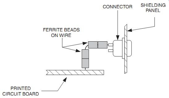
15-13 Computer connector fitted with ferrite beads.
Conclusion
EMI protection is often an afterthought in the design of electronic equipment. It should be a first requirement but, unfortunately, this isn't often the case. The methods shown herein will go a long way toward suppressing the RFI or transient conditions on the signal or power lines.