AMAZON multi-meters discounts AMAZON oscilloscope discounts
A vector (Fig. 18-1A) is a graphical device that is used to define the magnitude and direction (both are needed) of a quantity or physical phenomena. The length of the arrow defines the magnitude of the quantity, while the direction in which it is pointing defines the direction of action of the quantity being represented.
Vectors can be used in combination with each other. For example, in Fig. 18-1B we see a pair of displacement vectors that define a starting position (P1) and a final position (P2) for a person who traveled from point P1 12 miles north and then 8 miles east to arrive at point P2. The displacement in this system is the hypotenuse of the right triangle formed by the "north" vector and the "east" vector. This concept was once illustrated vividly by a university bumper sticker's directions to get to a rival school: "North 'til you smell it, east 'til you step in it." Figure 18-1C shows a calculations trick with vectors that is used a lot in engineering, science, and especially electronics. We can translate a vector parallel to its original direction and still treat it as valid. The "east" vector (E) has been translated parallel to its original position so that its tail is at the same point as the tail of the "north" vector (N). This allows us to use the Pythagorean theorem to define the vector. The magnitude of the displacement vector to P2 is given by:

(18-1)
But recall that the magnitude only describes part of the vector's attributes. The other part is the direction of the vector. In the case of Fig. 18-1C the direction can be defined as the angle between the "east" vector and the displacement vector. This angle (theta) is given by:

(18-2)
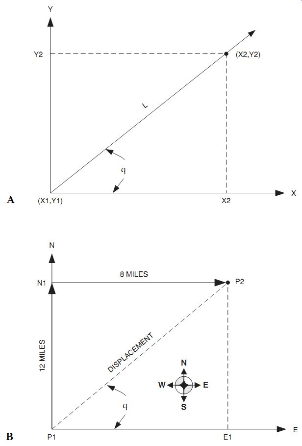
18-1 (A) Simple vector system; (B) N-E vector system; (C) Displacement vector.
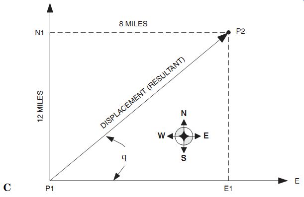
18-1 Continued.
In generic vector notation there is no "natural" or "standard" frame of reference so the vector can be drawn in any direction so long as the user understands what it means. In the system above, we have adopted-by convention-a method that is basically the same as the old-fashioned Cartesian coordinate system X-Y graph. In the example of Fig. 18-1B the X axis is the "east" vector while the Y axis is the "north" vector.
In electronics, the vectors are used to describe voltages and currents in ac circuits are standardized (Fig. 18-2) on this same kind of Cartesian system in which the inductive reactance (XL), i.e., the opposition to ac exhibited by inductors, is graphed in the "north" direction, the capacitive reactance (XC) is graphed in the "south" direction, and the resistance (R) is graphed in the "east" direction. Negative resistance ("west" direction) is sometimes seen in electronics. It is a phenomenon in which the current decreases when the voltage increases. RF examples of negative resistance include tunnel diodes and Gunn diodes.
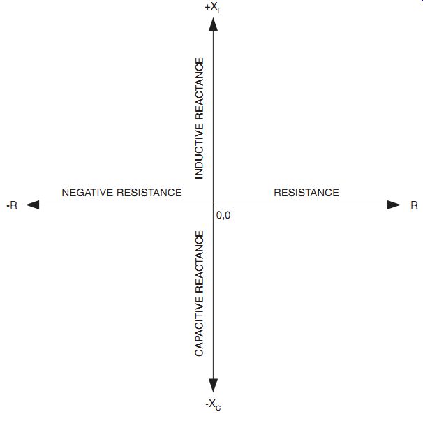
18-2 Vectors used in L-C circuits.