AMAZON multi-meters discounts AMAZON oscilloscope discounts
This section covers inductance (L) and capacitance (C), how they are affected by ac signals, and how they are combined into LC-tuned circuits. The tuned circuit allows the radio-frequency (RF) circuit to be selective about the frequency being passed. Alternatively, in the case of oscillators, LC components set the operating frequency of the circuit.
Tuned resonant circuits
Tuned resonant circuits, also called tank circuits or LC circuits, are used in the radio front end to select from the myriad of stations available at the antenna. The tuned resonant circuit is made up of two principal components: inductors and capacitors, also known in old radio books as condensers. This section examines inductors and capacitors separately, and then in combination, to determine how they function to tune a radio's RF, intermediate-frequency (IF), and local oscillator (LO) circuits. First, a brief digression is needed to discuss vectors because they are used in describing the behavior of these components and circuits.
Vectors
A vector ( FIG. 1A) is a graphical device that is used to define the magnitude and direction (both are needed) of a quantity or physical phenomenon. The length of the arrow defines the magnitude of the quantity, and the direction in which it points defines the direction of action of the quantity being represented.
Vectors can be used in combination with each other. For example, FIG. 1B shows a pair of displacement vectors that define a starting position (P1) and a final position (P2) for a person traveling 12 miles north from point P1 and then 8 miles east to arrive at point P2. The displacement in this system is the hypotenuse of the right triangle formed by the north vector and the east vector. This concept was once vividly illustrated by a university bumper sticker's directions to get to a rival school:
"North 'till you smell it, east 'til you step in it."
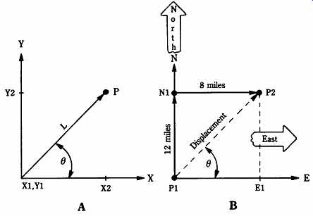
FIG. 1 (A) Vector notation is used in RF circuit analysis. The resultant
of vector X and vector Y is vector L between (X1, Y1) and (X2, Y2), or
point P; (B) A way of viewing vectors is to measure the displacement of a
journey that is 12 miles north and 8 miles east.
Another vector calculation trick is used a lot in engineering, science, and especially in electronics. You can translate a vector parallel to its original direction and still treat it as valid. The east vector (E) has been translated parallel to its original position so that its tail is at the same point as the tail of the north vector (N). This allows you to use the Pythagorean theorem to define the vector. The magnitude of the displacement vector to P2 is given by
P2=√N2+E2
(Eqn. 1)
But recall that the magnitude only describes part of the vector's attributes. The other part is the direction of the vector. In the case of FIG. 1B, the direction can be defined as the angle between the east vector and the displacement vector. This angle (θ) is given by
θ = arccos (E1/P)
(Eqn. 2)
In generic vector notation, there is no natural or standard frame of reference so that the vector can be drawn in any direction so long as the user understands what it means. This system has adopted a method that is basically the same as the old-fashioned Cartesian coordinate system X-Y graph. In the example of FIG. 1B, the X axis is the east-west vector and the Y axis is the north-south vector.
In electronics, vectors are used to describe voltages and currents in ac circuits.
They are standardized ( FIG. 2) on a similar Cartesian system where the inductive reactance (XL) (i.e., the opposition to ac exhibited by inductors) is graphed in the north direction, the capacitive reactance (XC) is graphed in the south direction, and the resistance (R) is graphed in the east direction.
Negative resistance (the west direction) is sometimes seen in electronics. It is a phenomenon in which the current decreases when the voltage increases. Some RF examples of negative resistance include tunnel diodes and Gunn diodes.
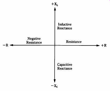
FIG. 2 Vector system used in ac or RF circuit analysis.
Inductance and inductors
Inductance is the property of electrical circuits that opposes changes in the flow of current. Notice the word "changes"-it is important. As such, it is somewhat analogous to the concept of inertia in mechanics. An inductor stores energy in a magnetic field (a fact that you will see is quite important). In order to understand the concept of inductance, you must understand three physical facts:
1. When an electrical conductor moves relative to a magnetic field, a current is generated (or induced) in the conductor. An electromotive force (EMF or voltage) appears across the ends of the conductor.
2. When a conductor is in a magnetic field that is changing, a current is induced in the conductor. As in the first case, an EMF is generated across the conductor.
3. When an electrical current moves in a conductor, a magnetic field is set up around the conductor.
According to Lenz's law, the EMF induced in a circuit is "-- in a direction that opposes the effect that produced it." From this fact, you can see the following effects:
1. A current induced by either the relative motion of a conductor and a magnetic field or changes in the magnetic field always flows in a direction that sets up a magnetic field that opposes the original magnetic field.
2. When a current flowing in a conductor changes, the magnetic field that it generates changes in a direction that induces a further current into the conductor that opposes the current change that caused the magnetic field to change.
3. The EMF generated by a change in current will have a polarity that is opposite to the polarity of the potential that created the original current.
Inductance is measured in henrys (H). The accepted definition of the henry is the inductance that creates an EMF of 1 V when the current in the inductor is changing at a rate of 1 A/S or
V= L(ΔI/Δt)(Eqn. 3)
where
V = induced EMF in volts (V)
L = inductance in henrys (H)
I = current in amperes (A)
t = time in seconds (s)
Δ = "small change in ... "
The henry (H) is the appropriate unit for inductors used as the smoothing filter chokes used in dc power supplies, but is far too large for RF and IF circuits. In those circuits, subunits of milli-henrys (mH) and micro-henrys (uH) are used. These are related to the henry as follows: 1 H = 1,000 mH = 1,000,000 uH. Thus, 1 mH = 10-3 H and 1 uH = 10-6 H.
The phenomena to be concerned with here is called self-inductance: when the current in a circuit changes, the magnetic field generated by that current change also changes. This changing magnetic field induces a countercurrent in the direction that opposes the original current change. This induced current also produces an EMF, which is called the counter electromotive force (CEMF). As with other forms of inductance, self-inductance is measured in henrys and its subunits.
Although inductance refers to several phenomena, when used alone it typically means self-inductance and will be so used in this section unless otherwise specified (e.g., mutual inductance). However, remember that the generic term can have more meanings than is commonly attributed to it.
Inductance of a single straight wire
Although it is commonly assumed that "inductors" are "coils," and therefore consist of at least one, usually more, turns of wire around a cylindrical form, it is also true that a single, straight piece of wire possesses inductance. This inductance of a wire in which the length is at least 1000 times its diameter (d) is given by the following:
(Eqn. 4)
The inductance values of representative small wires is very small in absolute numbers but at higher frequencies becomes a very appreciable portion of the whole inductance needed. Consider a 12" length of #30 wire (d = 0.010 in). Plugging these values into Eq. (Eqn. 4) yields the following:
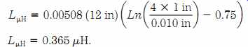
(Eqn. 5) , (Eqn. 6)
An inductance of 0.365 uH seems terribly small; at 1 MHz, it is small compared with inductances typically used as that frequency. But at 100 MHz, 0.365 uH could easily be more than the entire required circuit inductance. RF circuits have been created in which the inductance of a straight piece of wire is the total inductance.
But when the inductance is an unintended consequence of the circuit wiring, it can become a disaster at higher frequencies. Such unintended inductance is called stray inductance and can be reduced by using broad, flat conductors to wind the coils. An example is the printed circuit coils wound on cylindrical forms in the FM radio receiver tuner in FIG. 3.
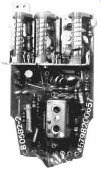
FIG. 3 Printed circuit inductors.
Self-inductance can be increased by forming the conductor into a multiturn coil ( FIG. 4) in such a manner that the magnetic field in adjacent turns reinforces itself.
This requirement means that the turns of the coil must be insulated from each other.
A coil wound in this manner is called an "inductor," or simply a "coil," in RF/IF circuits. To be technically correct, the inductor pictured in FIG. 4 is called a solenoid wound coil if the length (l) is greater than the diameter (d). The inductance of the coil is actually self-inductance, but the "self-" part is usually dropped and it is simply called inductance.
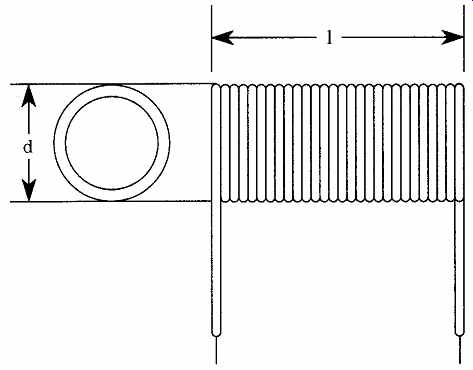
FIG. 4 Inductance is a function of the length (l) and diameter (d) of the
coil.
Several factors affect the inductance of a coil. Perhaps the most obvious factors are the length, the diameter, and the number of turns in the coil. Also affecting the inductance is the nature of the core material and its cross-sectional area. In the examples of FIG. 3, the core is simply air and the cross-sectional area is directly related to the diameter. In many radio circuits, the core is made of powdered iron or ferrite materials.
For an air-core solenoid coil, in which the length is greater than 0.4d, the inductance can be approximated by the following:
(Eqn. 7)
The core material has a certain magnetic permeability (μ), which is the ratio of the number of lines of flux produced by the coil with the core inserted to the number of lines of flux with an air core (i.e., core removed). The inductance of the coil is multiplied by the permeability of the core.
Combining inductors in series and in parallel
When inductors are connected together in a circuit, their inductances combine similar to the resistances of several resistors in parallel or in series. For inductors in which their respective magnetic fields do not interact, the following equations are used:
Series connected inductors:
(Eqn. 8)
Parallel connected inductors:
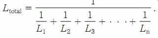
(Eqn. 9)
In the special case of the two inductors in parallel:
(Eqn. 10) If the magnetic fields of the inductors in the circuit interact, the total inductance becomes somewhat more complicated to express. For the simple case of two inductors in series, the expression would be as follows.
Series inductors:
(Eqn. 11)
...where ...
M = mutual inductance caused by the interaction of the two magnetic fields.
(Note: +M is used when the fields aid each other, and -M is used when the fields are opposing.)
Parallel inductors:
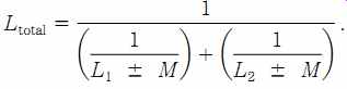
(Eqn. 12)
Some LC tank circuits use air-core coils in their tuning circuits (FIG. 5). Notice that two of the coils in FIG. 5 are aligned at right angles to the other one. The reason for this arrangement is not mere convenience but rather is a method used by the radio designer to prevent interaction of the magnetic fields of the respective coils. In general, for coils in close proximity to each other the following two principles apply:
1. Maximum interaction between the coils occurs when the coils' axes are parallel to each other.
2. Minimum interaction between the coils occurs when the coils' axes are at right angles to each other.
For the case where the coils' axes are along the same line, the interaction depends on the distance between the coils.
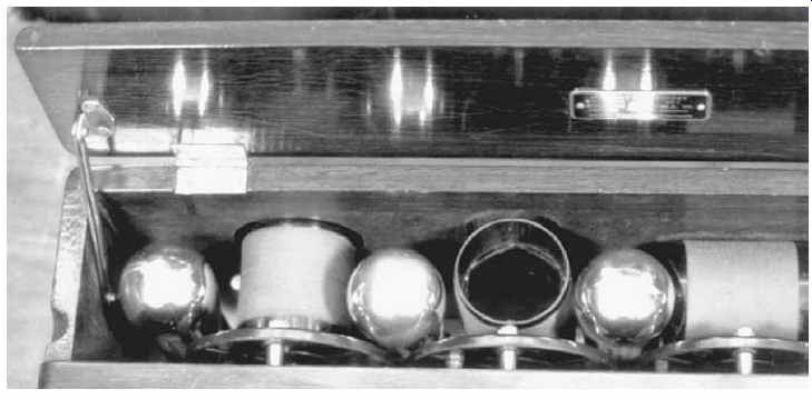
FIG. 5 Inductors in an antique radio set.
Inductor circuit symbols
FIG. 6 shows various circuit symbols used in schematic diagrams to represent inductors. Figures 6A and 6B represent alternate, but equivalent, forms of the same thing; i.e., a fixed value, air-core inductor ("coil" in the vernacular). The other forms of inductor symbol shown in FIG. 6 are based on FIG. 6A but are just as valid if the "open-loop" form of FIG. 6B is used instead.
The form shown in FIG. 6C is a tapped fixed-value air-core inductor. By providing a tap on the coil, different values of fixed inductance are achieved. The inductance from one end of the coil to the tap is a fraction of the inductance available across the entire coil. By providing one or more taps, several different fixed values of inductance can be selected. Radio receivers and transmitters sometimes use the tap method, along with a bandswitch, to select different tuning ranges or "bands." Variable inductors are shown in Figs. 2-6D and 2-6E. Both forms are used in schematic diagrams, although in some countries FIG. 6D implies a form of construction whereby a wiper or sliding electrical contact rides on the uninsulated turns of the coil. FIG. 6E implies a construction where variable inductance is achieved by moving a magnetic core inside of the coil.
FIG. 6F indicates a fixed value (or tapped, if desired) inductor with a powdered iron, ferrite or nonferrous (e.g., brass) core. The core will increase (ferrite or powdered iron) or decrease (brass) the inductance value relative to the same number of turns on an air core coil.

FIG. 6 Forms of inductor symbol: (A) fixed (open loop style); (B) fixed
(closed loop style); (C) tapped; (D) variable (style 1); (E) variable (style
2); (F) powered iron or ferrite slug-tuned core inductor.
Inductors in ac circuits
Impedance (Z) is the total opposition to the flow of ac in a circuit and as such it is analogous to resistance in dc circuits. Impedance is made up of a resistance component (R) and a component called reactance (X). Like resistance, reactance is measured in ohms. If the reactance is produced by an inductor, then it is called inductive reactance (XL) and if by a capacitor it is called capacitive reactance (XC).
Inductive reactance is a function of the inductance and the frequency of the ac source:
(Eqn. 13) XL = 2 π FL
where
XL = inductive reactance in ohms ()
F = ac frequency in hertz (Hz)
L = inductance in henrys (H).
In a purely resistive ac circuit ( FIG. 7A), the current (I) and voltage (V) are said to be in phase with each other (i.e., they rise and fall at exactly the same times in the ac cycle). In vector notation (FIG. 7B), the current and voltage vectors are along the same axis, which is an indication of the zero-degree phase difference be tween the two.
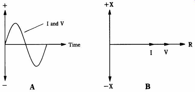
FIG. 7 (A) Current and voltage in phase with each other (sine wave with
vector notation); (B) vector relationship.
In an ac circuit that contains only an inductor ( FIG. 8A), and is excited by a sine-wave ac source, the change in current is opposed by the inductance. As a result, the current in an inductive circuit lags behind the voltage by 90 degrees. This is shown vectorially in FIG. 8B, and as a pair of sine waves in FIG. 8C.
The ac circuit that contains a resistance and an inductance ( FIG. 9B) shows a phase shift (θ), shown vectorially in FIG. 9A, other than the 90 difference seen in purely inductive circuits. The phase shift is proportional to the voltage across the inductor and the current flowing through it. The impedance of this circuit is found by the Pythagorean rule described earlier, also called the root of the sum of squares method (see FIG. 9):
(Eqn. 14)
The coils used in radio receivers come in a variety of different forms and types, but all radios (except the very crudest untuned crystal sets) will have at least one coil.
Now let us turn our attention to the other member of the LC tuned circuit, the capacitor.
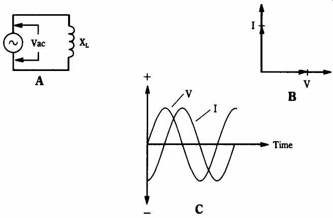
FIG. 8 (A) Inductor ac circuit; (B) vector relationships; (C) sine-wave
representation.
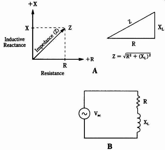
FIG. 9 (A) Resistor-inductor (RL) circuit; (B) vector relationships.
Air-core inductors
An air-core inductor actually has no core so it might also be called a coreless coil. Although it can be argued that the performance of an inductor differs between air and vacuum cores, the degree of difference is so negligible as to fall into the "decimal dust" category.
Three different forms of air-core inductor can be recognized. If the length (b) of a cylindrical coil is greater than, or equal to, the diameter (d) then the coil is said to be solenoid-wound. But if the length is much shorter than the diameter then the coil is said to be loop-wound. There is a gray area around the breakpoint between these inductors where the loop-wound coil seems to work somewhat like a solenoid-wound coil, but in the main most loop-wound coils are such that b
d. The principal uses of loop-wound coils is in making loop antennas for interference nulling and radio direction finding (RDF) applications.
Solenoid-wound air-core inductors
An example of the solenoid-wound air-core inductor was shown in FIG. 4. This form of coil is longer than its own diameter. The inductance of the solenoid-wound coil is given by the following:
(Eqn. 15)
...where ...
LuH is the inductance in microhenrys (uH)
a is the coil radius in inches (in)
b is the coil length in inches (in)
N is the number of turns in the coil.
This equation will allow calculation of the inductance of a known coil, but we usually need to know the number of turns (N) required to achieve some specific inductance value determined by the application. For this purpose, we rearrange the equation in the form:
(Eqn. 16)
Several different forms of solenoid-wound air-core inductor are shown in FIG. 10. The version shown in FIG. 10A is homemade on a form of 25-mm PVC plumbing pipe, sawn to a length of about 80 mm and fitted at one end with solder lugs secured with small machine screws and hex nuts. The main inductor is shown in the dark-colored #24 AWG enamel-coated wire, while a small winding is made from #26 AWG insulated hook-up wire. The use of two coaxial inductors makes this assembly a transformer. The small primary winding can be connected between ground and an aerial, and the larger secondary winding can be resonated with a variable capacitor.
The air-core coil shown in FIG. 10B is part of an older radio transmitter, where it forms the anode tuning inductance.
[ Amateur radio operators might recognize this unit as the Heathkit DX-60B transmitter.]
Because several different frequency bands must be accommodated, there are actually several coils on the same form. The required sections are switch-selected according to the band of operation. Another method for achieving tapped inductance is shown in FIG. 10C. This coil is a commercial air-core coil made by Barker & Williamson. Some models of this coil stock come with alternate windings indented to facilitate the connection of a tap. In any case, it is easy to press in the windings adjacent to the connection point. The variant shown in Fig. 6-10D was found, oddly enough, on a 1000-W HF motorcycle mobile.
The whip antenna is resonated by using an alligator clip to select the number of turns from the coil.
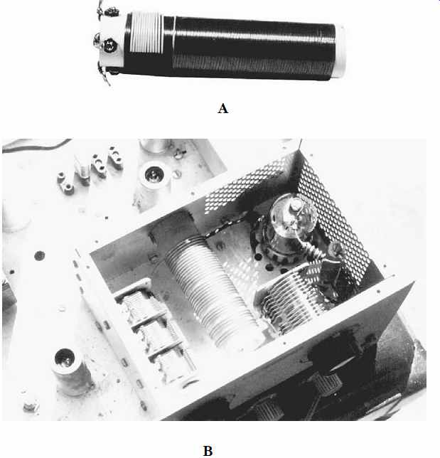
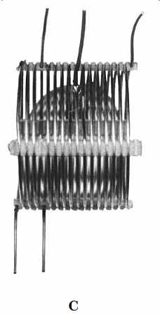
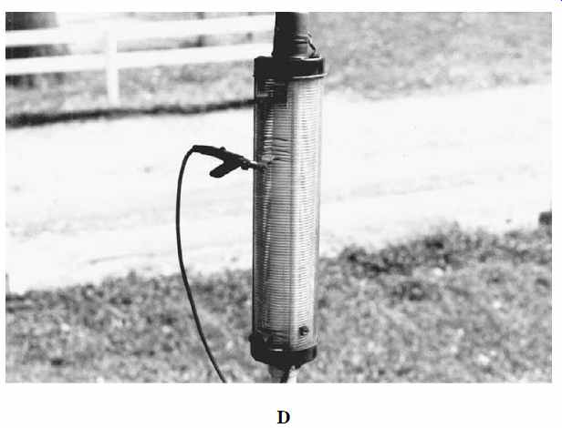
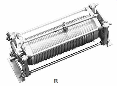
FIG.
10 (A) Solenoid wound inductor with transformer coupling link; (B) inductor
used as a tank circuit in radio transmitter; (C) tapped inductor; (D)
tapped inductor on mobile antenna; (E) roller inductor.
The air-core coil shown in FIG. 10E is a rotary inductor of the type found in some HF transmitters, antenna-tuning units, and other applications where continuous control of frequency is required. The inductor coil is mounted on a ceramic form that can be rotated using a shaft protruding from one end. As the form rotates, a movable shorting element rides along the turns of the coil to select the required inductance. Notice in FIG. 10E that the pitch (number of turns per unit length) is not constant along the length of the coil. This "pitch-winding" method is used to provide a nearly constant change of inductance for each revolution of the adjustment shaft.
Adjustable coils
There are several practical problems with the preceding standard fixed coil. For one thing, the inductance cannot easily be adjusted-either to tune the radio or to trim the tuning circuits to account for the tolerances in the circuit.
Air-core coils are difficult to adjust. They can be lengthened or shortened, the number of turns can be changed, or a tap or series of taps can be established on the coil in order to allow an external switch to select the number of turns that are allowed to be effective. None of these methods is terribly elegant-even though all have been used in one application or another.
The solution to the adjustable inductor problem that was developed relatively early in the history of mass-produced radios, and is still used today, is to insert a powdered iron or ferrite core (or "slug") inside the coil form ( FIG. 11). The permeability of the core will increase or decrease the inductance according to how much of the core is inside the coil. If the core is made with either a hexagonal hole or screwdriver slot, then the inductance of the coil can be adjusted by moving the core in or out of the coil. These coils are called slug-tuned inductors.
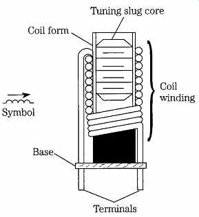
FIG. 11 Slug-tuned ferrite or powdered iron-core inductor.
Capacitors and capacitance
Capacitors are the other component used in radio tuning circuits. Like the inductor, the capacitor is an energy-storage device. Although the inductor stores electrical energy in a magnetic field, the capacitor stores energy in an electrical (or "electrostatic") field. Electrical charge, Q, is stored in the capacitor. But more about that shortly.
The basic capacitor consists of a pair of metallic plates that face each other and are separated by an insulating material, called a dielectric. This arrangement is shown schematically in FIG. 12A and in a more physical sense in FIG. 12B. The fixed capacitor shown in FIG. 12B consists of a pair of square metal plates separated by a dielectric. Although this type of capacitor is not terribly practical, it was once used quite a bit in transmitters. Spark transmitters of the 1920s often used a glass and tinfoil capacitor that looked very much like FIG. 12B. Layers of glass and foil are sandwiched together to form a high-voltage capacitor. A 1-ft square capacitor made of 1 x 8-in-thick glass and foil has a capacitance of about 2000 picofarads (pF).
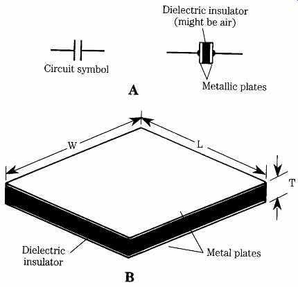
FIG. 12 (A) Capacitors consist of a pair of conductors separated by a dielectric
(insulator); (B) parallel plate capacitor.
Units of capacitance
Capacitance (C) is a measure of a capacitor's ability to store current or, more properly, electrical charge. The principal unit of capacitance is the farad (F) (named after physicist Michael Faraday). One farad is the capacitance that will store one coulomb of electrical charge (6.28 _ 1018 electrons) at an electrical potential of 1 V, or, in math form:
1F =1Q /1V (Eqn. 17)
where
C = capacitance in farads (F)
Q = electrical charge in coulombs (q)
V = electrical potential in volts (V)
The farad is far too large for practical electronics work, so subunits are used.
The microfarad ( uF) is 0.000001 farads (1F = 10^6 uF). The picofarad (pF) is 0.000001 uF =10-12 farads. In older radio texts and schematics, the picofarad was called the micro-microfarad (u u F).
The capacitance of the capacitor is directly proportional to the area of the plates (in terms of FIG. 12B, L x W), inversely proportional to the thickness (T) of the dielectric (or the spacing between the plates, if you prefer), and directly proportional to the dielectric constant (K) of the dielectric.
The dielectric constant is a property of the insulating material used for the di electric. The dielectric constant is a measure of the material's ability to support electric flux and is thus analogous to the permeability of a magnetic material. The standard of reference for the dielectric constant is a perfect vacuum, which is said to have a value of K = 1.00000. Other materials are compared with the vacuum. The values of K for some common materials are as follows:
• vacuum: 1.0000
• dry air: 1.0006
• paraffin (wax) paper: 3.5
• glass: 5 to 10
• mica: 3 to 6
• rubber: 2.5 to 35
• dry wood: 2.5 to 8
• pure (distilled) water: 81
The value of capacitance in any given capacitor is found using the following:
C= [0.0885 K A (N - 1)]/1
(Eqn. 18)
...where ...
C = capacitance in picofarads
K = dielectric constant
A = area of one of the plates (LxW), assuming that the two plates are identical
N = number of identical plates
T = thickness of the dielectric.
Breakdown voltage
The capacitor works by supporting an electrical field between two metal plates.
This potential, however, can get too large. When the electrical potential (i.e., the voltage) gets too large, free electrons in the dielectric material (there are a few, but not too many, in any insulator) might flow. If a stream of electrons gets started, then the dielectric might break down and allow a current to pass between the plates. The capacitor is then shorted. The maximum breakdown voltage of the capacitor must not be exceeded. However, for practical purposes, there is a smaller voltage called the dc working voltage (WVdc) rating, which is the maximum safe voltage that can be applied to the capacitor. Typical values found in common electronic circuits are from 8 to 1000 WVdc, with values to many kilovolts less commonly available.
Circuit symbols for capacitors
The circuit symbols used to designate fixed-value capacitors are shown in FIG. 13A. Both types of symbols are common. In certain types of capacitors, the curved plate shown on the left in FIG. 13A is usually the outer plate (i.e., the one closest to the outside package of the capacitor). This end of the capacitor is often indicated by a colored band next to the lead attached to that plate.
The symbol for the variable capacitor is shown in FIG. 13B. The symbol for a variable capacitor is the fixed-value symbol with an arrow through the plates. Small trimmer and padder capacitors are often denoted by the symbol in FIG. 13C. The variable set of plates is designated by the arrow.
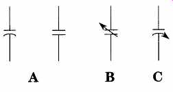
FIG. 13 Capacitor symbols: (A) fixed-value; (B) variable; (C) trimmer and
padder.