AMAZON multi-meters discounts AMAZON oscilloscope discounts
Doping out transmission line difficulties can be a tedious and difficult chore-especially when the load end is not easily accessible. Although there are a number of different methods available, I want to discuss time-domain reflectometry. Although the official, bottled-in-bond, 100-proof time-domain reflectometer (TDR) is a terribly ex pensive piece of equipment, some TDR methods can be used by any amateur who has access to an oscilloscope. Will the results be as good as professional TDR equipment? In a word: no. Will the results be useful in troubleshooting a transmission line? In a single word: yes.
The basis of TDR
Time-domain reflectometry works on the principle that waves on a non-matched transmission line reflect. The waveform seen at any given point along the line is the algebraic sum of the forward and reflected waveforms. In TDR measurements, we look at the waveform at the input end of the transmission line system.
Figure 24-1 shows the basic set-up for our impromptu TDR. A pulse generator, or other source of 1-MHz square waves, is applied simultaneously to the vertical in put of an oscilloscope and the input end of the transmission line. This neat little trick is accomplished with an ordinary coaxial tee connector, either BNC or UHF, de pending on your own situation. In my case, the pulse source and oscilloscope use BNC connectors, so I used a BNC tee connector. The PL-259 UHF connector on the end of the 200-foot length of RG-58 transmission line was converted using a SO-239 to BNC male adapter. In years gone by, that adapter was a $20 bench accessory, but today, the advent of VCRs and other such products has spawned a line of low-cost coax adapters that will darn near allow us to adapt anything to anything.
The pulse source
Almost any source of square waves in the vicinity of 1 MHz can be used for the pulse generator. If you have one of those function generators that output pulses to 1 MHz or more, then use it. Be careful, however, if the output impedance is 600 ohm (as some are). For those, you might want to fashion a 600- to 50-ohm transformer or a simple resistor pad. Alternatively, you can build your own pulse source.
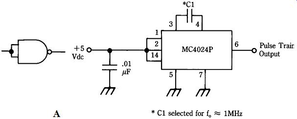
Many different forms of TTL oscillators can be used as a pulse source. Figure 24-2A shows the circuit for a pulse generator based on the Motorola MC-4024P device. This chip is not from the CMOS line, despite its 4000-series type number. It is a dual, TTL compatible, voltage-controlled oscillator (VCO). It has a TTL part number 74424.
The circuit is built inside of a shielded box. The operating frequency is given very approximately by the equation F = 300/C, where F is in megahertz (MHz) and C is in picofarads (pF). The actual operating frequency is not terribly critical, as long as it is somewhere near 1 MHz. For very short transmission lines, the operating frequency may have to be increased-experiment with it.
The output waveform is a square wave with a period of about 1.1 (uS) when C1 =330 pF. The half-cycle used in the experiment (see Fig. 24-2B) has a period of one-half that, or 550 (0.55 us). If you want to clean up the rise and fall times of the output waveform then pass the output through either an inverter made from H series TTL or a Schmitt trigger (7414). The inset to Fig. 24-2A shows an inverter made by strapping the inputs of a 74H00 NAND gate.
Figure 24-2B is our comparison for considering the waveforms to follow. Figure 24-2B was photographed from my oscilloscope with the coaxial cable disconnected.
The photos to follow show what this pulse looks like when a reflected pulse hits it after returning down the transmission line.
Another alternate for our pulse generator is to use a crystal oscillator on 1 MHz, 2 MHz, and so on. These oscillators can then also serve as a marker generator for other purposes. The tuning calibration is a bear. I am contemplating a 20-MHz TTL crystal oscillator that will have TTL frequency dividers in cascade to obtain 10-MHz, 5-MHz, 2-MHz, 1-MHz, 500-kHz, 100-kHz, 50-kHz, and 10-kHz outputs. There is no reason why that marker generator can't be used as the pulse source in TDR measurements.
24-1 Set-up for time-domain reflectometry measurements.
24-2 (A) Easy to build pulse generator circuit and (B) output pulses.
Test set-up
The test set-up of Fig. 24-1 was built for these measurements. The load box at the antenna end of the transmission line was a little multi-Z dummy load that I use for various workshop applications and is shown in Fig. 24-3. I can select an external dummy load, a short circuit, and a total of 10 discrete impedances. When the external dummy load is disconnected, the load box sees an open transmission line in that switch position. Why have a load box? It is not part of the TDR, but helped to calibrate the system and generate the pictures that follow. You don't need one for your own TDR, even though I recommend load boxes as a workshop adjunct.
Why have 12 different loads, you say? Because I had a single-pole, 12-position rotary switch in my junk box, that's why. The impedance values shown were selected to (hopefully) represent a wide range of actual impedances typically encountered in amateur antennas.
24-3 Dummy load box.
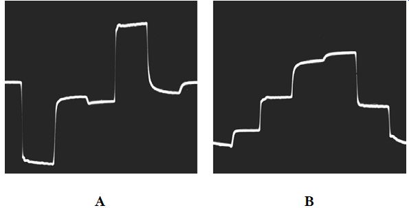
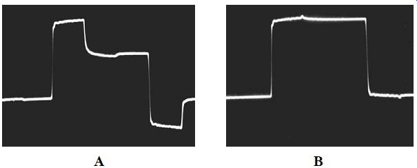
24-4 (A) Shorted line and (B) open line.
Some actual measurements
Figure 24-4 shows two conditions that often show up on transmission lines: open and short-circuited. It is rarely of practical difference which occurs because both need to be corrected at the antenna end. However, should it be important, you can-not differentiate which is which by the VSWR reading. In both cases, the entire incident wave is reflected. The only difference is the location of the nodes and anti nodes, which are out of phase with each other. If the precise electrical length of the line is known, then you can infer from that whether the line is open or shorted. Otherwise, you make a TDR measurement.
24-5 (A) Matched load and transmission line, (B) ZL < Zo, and (C) ZL > Zo.
Figure 24-4A shows the waveform when the load end of the line is short circuited (in other words, ZL = 0). The opposite case, an open-circuited line (impedance infinite) is shown in Fig. 24-4B. You can infer from the wave shape whether the line is open or shorted. In both cases, I experimented with several different lengths of RG-58/U coax up to 200 ft long and found similar waveforms in each case.
As you might suspect, impedances between zero and infinite are represented by various combinations of the two waveforms shown in Fig. 24-4. Figure 24-5 shows some of these waveforms. Figure 24-5A shows the supposedly matched 50-ohm case. If the system were perfect, the top edge of the pulse would be totally flat. The actual resistor used in the load box was a 51-ohm, 5-percenter. In addition, there is bound to be some reactance in the load and possible anomalies in the coax itself. I have per- formed this little experiment before using a noninductive 200-ohm potentiometer as the load and was able to all but totally adjust out the lack of flatness. As you will see in a moment, the waveform in Fig. 24-5A represents a real load impedance greater than 50-ohm.
The waveform shown in Fig. 24-5B is for a 22-ohm load. This impedance is common on vertical antennas. Nominal impedance for one-quarter wavelength vertical is 37 ohm, but actual impedances are likely to be lower in practical installations (that's why Palomar Engineers sell their fantastic impedance transformer).
As the load impedance values slip above the surge impedance of the cable (50-ohm for RG-58/U), the waveform takes on a different shape. Instead of the reflected impedance causing a little rise in the flat edge, it causes a droop. Figure 24-5C, you can see that the amount of droop is related to how far above the surge impedance the load is.