AMAZON multi-meters discounts AMAZON oscilloscope discounts
Few circuit problems are less welcomed than frequency drift. This problem is characterized by the radio transmitter or receiver changing frequency not under the in fluence of the operator. Actually, two different problems are seemingly related: drift and shift. Drift is a gradual change of frequency, usually as a function of temperature.
Shift, on the other hand, is an abrupt change of frequency. The causes of these two related phenomena are different, but they are often confused with each other.
There is also a difference between problems with new projects and drift on old equipment that once worked well. On a newly constructed project, or new equipment from less reputable sources, the problem might well be an inherent error in the design (some easily corrected, others not). On equipment that once worked well, however, you have a problem of a failed component.
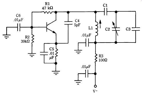
25-1 VHF VFO circuit.
Frequency shift problems
Resonant circuits in modern electronic equipment might be LC-tuned by a combination of inductance and capacitance or tuned by a piezoelectric resonator element (crystal). In either event, the cause of a sudden unwanted shift of operating frequency is usually some form of mechanical trauma somewhere in the circuit. In other words, some component is either broken or has an intermittent connection.
Figure 25-1 shows a partial circuit of an oscillator. The resonance of this circuit is determined by the combination of C1/C2/C3/L1. If any of these components fail, change value, or become disconnected then the resonant frequency of the circuit will shift. If coil L1 fails, then the circuit will probably cease oscillating, so the fault becomes obvious. But what if one of the capacitors fails? In that case, the circuit might well continue oscillating, but at a different frequency than before.
The trimmer capacitor was selected for our example in Fig. 25-1 because those components seem especially at fault. After many years of experience, I can attest that trimmers seem to have a high casualty rate. Perhaps the worst offenders are the half-turn type that use silver deposited on a pair of ceramic surfaces. The mica compression types also fail, but seem less prone than the other types. The mechanism of failure seems to be looseness in the adjustment screw. Tap the capacitor gently with an insulated probe and note whether the shift occurs.
Don't make the mistake of assuming that the other forms are fault-free; far from it. Every form of fixed capacitor has at least a small failure rate, usually caused by disconnected leads inside the body of the capacitor.
Also, don't overlook the possibility that the problem is caused by the solder connections on the capacitor-especially where the capacitor is mounted on a printed wiring board that is easy to flex. Although some bad joints escape the factory QA inspector and subsequently last for years in service before failing, others die an early death because of trauma or flexing of the board. In addition to solder joint breaks, it is also possible that the printed wiring track is cracked. In both cases, a little solder and a hot iron will solve the problem.
One of my professional colleagues is a semi-active amateur operator with a receiver-transmitter pair that was once top of the line in amateur circles. He noticed that the formerly very good receiver dial calibration was now about 25 kHz off. On inspecting the LO VFO circuit, he found that it contained a number of small fixed capacitors in addition to the frequency setting trimmer and the main tuning variable capacitor. He made a few quick calculations of resonance to see which, if any, would result in about 25-kHz shift if it were open. He quickly identified a 27-pF unit that was part of the temperature-compensation circuit. A new 27-pF N1500 unit solved the problem. When you find a disk ceramic capacitor with a specified temperature coefficient, please don't make the mistake of thinking a low-temperature coefficient type is a better replacement. Also, don't use another disk with a different tempera ture coefficient.
On older receivers, be sure to examine the main tuning capacitor for problems.
I once had a terrible problem with a piece of equipment that exhibited both shift and drift in magnificent proportions. Although employed in a communications shop at the time, I did not get around to fixing the receiver for several months ("cobbler's kid's shoes" syndrome). When I looked into the problem it turned out to be crud under the rotor grounding spring on the main tuning capacitor. That capacitor rotor is normally grounded to the chassis through its own frame but because the rotor must move, a brass or steel grounding leaf spring or spider clip is usually placed around the rotor at the front bearing. The spring or clip grounds the rotor to the frame. In this case, a lot of dirty grease built up under the spring. Rather than cause operation to cease, however, the result was massive frequency shifts, drift when it wasn't shifting, and a sad tendency toward microphonics.
Another problem on older receivers is poor grounding. I have seen frequency shift problems on many car radios, two-way radios, and other RF equipment caused by poor grounding or cracked ground tracks on the printed circuit board. In one in famous FM model, the FM front end was grounded at only two points on the printed circuit. If that wasn't bad enough, the ground ran around the edge of the card and was stressed at one point, so cracks tended to develop. Although the circuit would not cease oscillating, the several extra inches of ground line on a flexing board caused operating frequency shifts. I suspect that the cause of the frequency shift was the added inductance of the printed circuit ground path. At VHF frequencies, the effect of distributed inductance or capacitance is more profound than at low frequencies.
Again, judicious use of a soldering iron not only repaired the break but also added strength to the weak point.
Drift problems
The other frequency changing problem is old-fashioned drift. Unfortunately, most electronic components exhibit some temperature sensitivity. This sensitivity is usually measured in terms of a temperature coefficient, which specifies a certain shift of value in parts per million (ppm) per degree Celsius of temperature shift. The temperature coefficient (Tc) can be either positive or negative. A positive tempera ture coefficient (PTc) indicates the value increases with increases in temperature. A negative temperature coefficient (NTc) indicates that the value tends to decrease with increases in temperature.
Most inductors used in oscillator circuits have a PTC problem. The value of inductance (microhenrys) is determined by the coil dimensions and the number of turns of wire. Although the turn-count remains constant, the diameter, length, and the size of the wire used in the inductor is a function of temperature. Temperature coefficient of inductors can be minimized by design. If the inductor uses Litz wire (or some other low-Tc wire) and a low-Tc coil form then the temperature coefficient is reduced tremendously. Old-fashioned cardboard forms are terrible sources of drift.
According to the old standard wisdom, the best forms are ceramic, but that is not true any longer. There are fiberglass and other synthetic materials that now provide better Tc characteristics.
Capacitors are also sources of Tc problems. Ceramic capacitors are available in either PTc, NTc, or no-Tc versions. Markings of "Nxxx" and "Pxxx" indicate the direction and amount of temperature coefficient. For example, an N750 is an NTc de vice with a Tc of 750 ppm. The capacitor marked NPO has a low Tc but not precisely zero-as some people find out to their chagrin when subbing really low-Tc caps with NPO ceramic units. In general, silver mica and polystyrene capacitors are the lowest-Tc units available.
So, why not make all capacitors with low or nearly zero Tc? The reason is that they are sometimes used in temperature compensation circuits. Figure 25-2 shows two forms of oscillator: one LC-tuned and the other crystal-tuned. Both of these oscillators seem to have extra capacitors in the circuit. For example, C2 in Fig. 25-2A and C1/C2 in Fig. 25-2B. In these cases, the extra capacitors are for temperature compensation.
They are typically small-value compared with other circuit capacitors, but have pre calculated TcS that will cause the capacitance to change a predictable amount with changes in temperature. Both circuits, even the crystal oscillator, will change frequency with changes in circuit capacitance, so the Tc of the compensation capacitors forces the frequency to change in a predictable manner. The idea is to counter the PTc of the inductor with an equal and opposite-direction Tc of the capacitors.
Unfortunately, even some manufacturers don't understand drift. Several years ago, I wrote a column for World Radio. In one column, I passed along a request for information sent in by an amateur working in the jungles of Central America. He had a low cost transceiver that made a brief splash on the amateur market. His problem was that it drifted badly and in fact had always drifted (even new). My request was answered by an engineer at Stoner Communications who passed along the information that the rig had been designed by a consulting design engineer whose reputation is spotless. His name is well known to technically oriented amateurs, but I suspect he prefers privacy.
Contacting the designer, I found that the original prototypes and first production units had a drift spec of 100 Hz in the first 15 min and 50 Hz/hr thereafter; not terrific, but good for a cheap rig. Furthermore, those early rigs actually met the specification. So, what happened? The designer told me that the original design used Litz wire in the VFO inductor and a special low-Tc fiberglass form. The VFO also used DM-25 silver mica capacitors, except for a couple of ceramics used for temperature compensation. The inexperienced manufacturer used a "kid technician" to redesign the rig to make it cheaper to produce. The technician replaced the Litz wire with enameled wire, the coil form with an off-the-shelf ceramic type, and the DM-25 SM capacitors with NPO disk ceramics. The result was a disaster.
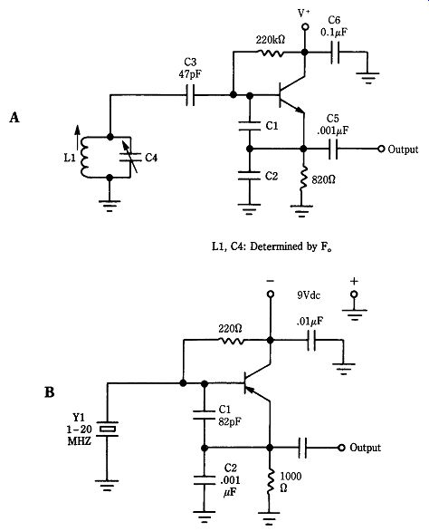
25-2 (A) Colpitts oscillator and (B) crystal Colpitts oscillator.
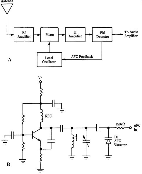
25-3 (A) Superheterodyne FM radio receiver and (B) local oscillator with
AFC varactor diode.
VHF problems
Figure 25-3A shows the block diagram of a FM receiver. The LO (example in Fig. 25-3B) is kept on channel by a dc control voltage from the automatic frequency control (AFC) output of the FM detector stage. The actual mechanism of frequency control is the variable capacitance (varactor) diode in the oscillator circuit (D1 in Fig. 25-3B). This type of diode is used in both LC tuned circuits, as used in broadcast receivers, as well as crystal-controlled units used in communications equipment. If the varactor becomes defective then it will cause a frequency shift. Alternatively, if the diode is intermittent, then the circuit will jump on and off channel as the diode opens and closes the circuit. I have, however, seen quite a number of sets over the years in which a newly developed (as opposed to inherent) drift problem was caused by a defective diode. For some reason, the diode capacitance was a function of temperature. Although not a scientific experiment, I once measured about five diodes that show this phenomenon and found that all had excessive leakage resistance in the reverse bias direction.
Don't overlook the dc power supply as a potential source of drift problems. Oscillators typically require fixed, well-regulated dc operating potentials for best stability. That dictum applies equally well to both LC-tuned and crystal oscillators. If the dc voltage or bias voltages change then expect an oscillator frequency shift.
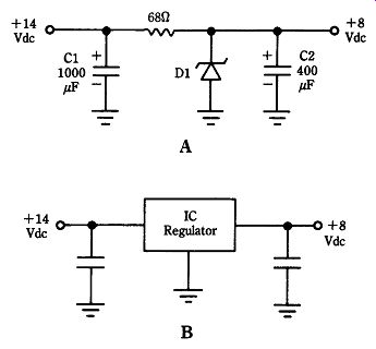
25-4 Voltage regulator circuits: (A) zener diode and (B) IC regulator.
The problem with dc voltage is especially acute in mobile equipment, whether communications or broadcast equipment. In the early 1960s, I worked in a car radio shop that dealt with Blaupunkt receivers (the German-made set in Porsche cars).
One customer came in with an odd problem: the radio changed frequency with changes of engine speed. That set, which used vacuum tubes, had a germanium diode across the resonant circuit to limit oscillation amplitude. A gas-regulator tube supposedly kept the potentials applied to the circuit, but it was defective. Because the car power supply varies markedly with engine speed, the now unregulated power-supply voltage applied to the oscillator also varied. One lesson: although I frequently chuckled at a customer's diagnosis, I never again doubted the customer's description of the symptom (". . . changes station when I pull away from a light . . .").
Modern mobile electronic equipment is probably more prone than some of the older equipment to this type of fault. In communications equipment and FM broad cast receivers, the oscillator voltage is typically regulated. Figure 25-4A shows the zener diode regulator typically used in many car radio circuits, and Figure 25-4B shows the three-terminal IC voltage regulator that keeps the oscillator voltage to 10 V in a certain mobile transmitter master oscillator. If any of these components faults, then shift or drift will result. The nominal 12-V vehicle power supply is actually quite variable. With the engine off, my own car measured 11.8-Vdc on one meter and 12.05-Vdc on my DMM. When the engine is started, however, the voltage varies from 12.3-Vdc at idle to 14.5-Vdc as the engine speed is increased. To an oscillator in electronic equipment, that range might be intolerable.
Crystal oscillators are not immune to drift problems, even when they previously worked well. In addition to the problems with dc power supplies, it is also possible for the crystal to become defective. I have seen several sets over the years in which a terrible drift problem resulted from defective crystal elements. Replacing the crystal solved the problem.
Problems with older equipment
Certain older amateur equipment exhibits a problem in frequency shift that is caused by the use of ferrite cores in the VFO and IF coils. Ferrite cores age with time and heat and as a result have a different permeability than when the equipment was first calibrated. I have seen that problem even on the legendary Collins permeability tuned oscillator (PTO) used in their amateur and commercial communications equipment. In some cases, a simple realignment will suffice to bring the coil back to the correct resonant frequency. In other cases, replacement of the coil, or at least the ferrite core, is required.
Several years ago I had the opportunity to help a novice on the air with a 20-year-old Heath DX-60B that he bought for a song at the Gaithersburg Hamfest. He complained that keying was erratic: sometimes it keyed, other times it did not. It rapidly became apparent by looking at the grid and plate meter readings that the oscillator was not running all the time. It turned out that the DX-60B crystal oscillator circuit uses a tuned plate circuit. The ferrite core of the coil had dried out over the years and mis tuned the oscillator. Readjusting the coil made the oscillator run properly.
Heat problems Because the root of many drift problems is the temperature coefficient of capacitors and inductors, it seems obvious that temperature needs to be controlled in radio equipment. In the past, several otherwise well-regarded pieces of equipment suffered drift because of the tremendous heat inside the cabinet. Ventilation and a blower might help in some cases. In other cases, using a little insulation in and around the of fending oscillator is also helpful. In certain crystal oscillator circuits, you can make progress by designing in a crystal oven to keep the crystal temperature constant.
Equipment modifications
Amateurs have a long tradition of modifying commercial equipment. Although many mods are ill-advised, some are certainly worthwhile and well-engineered. The process is a lot less dangerous, incidentally, if you make good notes so that the rig can be restored to original condition if the mod doesn't work out as expected. For most equipment, the first place to start is ensuring the power-supply voltage to the oscillator is stable. Furthermore, make certain that the printed circuit, its mounting, and the individual components are solidly anchored. Finally, be sure the circuit is not overheating.
If those methods fail to solve the problem, then and only then should you dive into the circuit to attempt temperature compensation. If you have any insight on procedures, techniques, and so forth then please communicate them to me so that they can be shared with others.
Frequency shift and drift problems are not easily found in many cases. Under standing the causes and potential solutions of these problems goes a long way to ward finding the fault in any particular case.