AMAZON multi-meters discounts AMAZON oscilloscope discounts
Like all capacitors, variable capacitors are made by placing two sets of metal plates parallel to each other (FIG. 1A) separated by a dielectric of air, mica, ceramic, or a vacuum. The difference between variable and fixed capacitors is that, in variable capacitors, the plates are constructed in such a way that the capacitance can be changed. There are two principal ways to vary the capacitance: either the spacing between the plates is varied or the cross-sectional area of the plates that face each other is varied. FIG. 1B shows the construction of a typical variable capacitor used for the main tuning control in radio receivers. The capacitor consists of two sets of parallel plates. The stator plates are fixed in their position and are attached to the frame of the capacitor. The rotor plates are attached to the shaft that is used to ad just the capacitance.
Another form of variable capacitor used in radio receivers is the compression capacitor shown in FIG. 1C. It consists of metal plates separated by sheets of mica di electric. In order to increase the capacitance, the manufacturer may increase the area of the plates and mica or the number of layers (alternating mica/metal) in the assembly. The entire capacitor will be mounted on a ceramic or other form of holder. If mounting screws or holes are provided then they will be part of the holder assembly.
Still another form of variable capacitor is the piston capacitor shown in FIG. 1D. This type of capacitor consists of an inner cylinder of metal coaxial to, and in side of, an outer cylinder of metal. An air, vacuum, or (as shown) ceramic dielectric separates the two cylinders. The capacitance is increased by inserting the inner cylinder further into the outer cylinder.
The small-compression or piston-style variable capacitors are sometimes combined with air variable capacitors. Although not exactly correct word usage, the smaller capacitor used in conjunction with the larger air variable is called a trimmer capacitor. These capacitors are often mounted directly on the air variable frame or very close by in the circuit. In many cases, the "trimmer" is actually part of the air variable capacitor.
There are actually two uses for small variable capacitors in conjunction with the main tuning capacitor in radios. First, there is the true "trimmer," i.e., a small-valued variable capacitor in parallel with the main capacitor (FIG. 2A). These trimmer capacitors (C2) are used to trim the exact value of the main capacitor (C1). The other form of small capacitor is the padder capacitor (FIG. 2B), which is connected in series with the main capacitor. This error in terminology is calling both series and parallel capacitors "trimmers," when only the parallel connected capacitor is properly so-called.
The capacitance of an air variable capacitor at any given setting is a function of how much of the rotor plate set is shaded by the stator plates. In FIG. 3A, the rotor plates are completely outside of the stator plate area. Because the shading is zero, the capacitance is minimum. In FIG. 3B, however, the rotor plate set has been slightly meshed with the stator plate, so some of its area is shaded by the stator. The capacitance in this position is at an intermediate-value. Finally, in FIG. 3C, the rotor is completely meshed with the stator so the cross-sectional area of the rotor that is shaded by the stator is maximum. Therefore, the capacitance is also maximum.
Remember these two rules:
1. Minimum capacitance is found when the rotor plates are completely unmeshed with the stator plates; and
2. Maximum capacitance is found when the rotor plates are completely meshed with the stator plates.
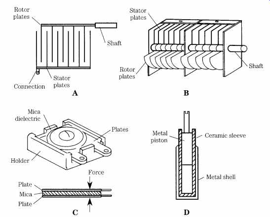
FIG. 1 Air dielectric variable capacitors consists of interleaved stator
and rotor plates. (A) Schematic view; (B) construction; (C) mica compression
variable capacitor; (D) piston variable capacitor.
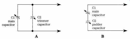
FIG. 2 (A) Trimmer capacitor connected in parallel with the main tuning capacitor;
(B) padder capacitor is connected in series with the main tuning capacitor.
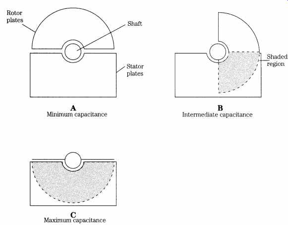
FIG. 3 The capacitance of the air variable capacitor is determined by how much
of the rotor plate is shaded by the stator plates. (A) Minimum capacitance;
(B) intermediate capacitance; (C) maximum capacitance.
FIG. 4 shows a typical single-section variable capacitor. The stator plates are attached to the frame of the capacitor, which in most radio circuits is grounded.
Front and rear mounts have bearing surfaces to ease the rotor's action. The ganged variable capacitor (FIG. 5) was invented to provide tracking between two related LC-tuned circuits, as in a radio receiver. Such capacitors are basically two (in the case of FIG. 5) or more variable capacitors mechanically ganged on the same rotor shaft.
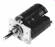
FIG. 4 Small air variable capacitor.
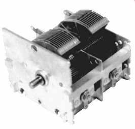
FIG. 5 Dual section air variable capacitor.
In FIG. 5, both sections of the variable capacitor have the same capacitance, so they are identical to each other. If this capacitor is used in a superheterodyne radio, the section used for the local oscillator (LO) tuning must be padded with a series capacitance in order to reduce the overall capacitance. This trick is done to permit the higher-frequency LO to track with the RF amplifiers on the dial.
In many superheterodyne radios, you will find variable tuning capacitors in which one section (usually the front section) has fewer plates than the other section.
One section tunes the RF amplifier of the radio, and the other tunes the local oscillator. These capacitors are sometimes called cut-plate capacitors because the LO section plates are cut to permit tracking of the LO with the RF.
Straight-line capacitance vs straight-line frequency capacitors
The variable capacitor shown in FIG. 5 has the rotor shaft in the geometric center of the rotor plate half-circle. The capacitance of this type of variable capacitor varies directly with the rotor shaft angle. As a result, this type of capacitor is called a straight-line capacitance model. Unfortunately, as you will see in a later section, the frequency of a tuned circuit based on inductors and capacitors is not a linear (straight line) function of capacitance. If a straight line capacitance unit is used for the tuner, then the frequency units on the dial will be cramped at one end and spread out at the other (you've probably seen such radios). But some capacitors have an offset rotor shaft (FIG. 6A) that compensates for the nonlinearity of the tuning circuit. The shape of the plates and the location of the rotor shaft are de signed to produce a linear relationship between the shaft angle and the resonant frequency of the tuned circuit in which the capacitor is used. A comparison between straight-line capacitance and straight-line frequency capacitors is shown in FIG. 6B.
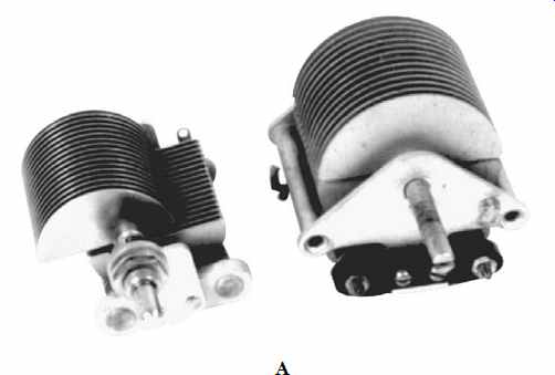
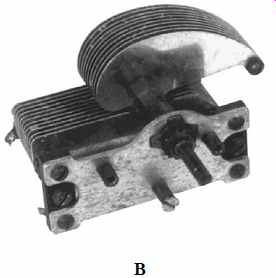
FIG. 6 (A) Straight-line frequency capacitor; (B) comparison of straight-line
capacitance with straight-line frequency capacitor.
Special variable capacitors
In the preceding sections, the standard forms of variable capacitor were covered. These capacitors are largely used for tuning radio receivers, oscillators, signal generators, and other variable-frequency LC oscillators. This section covers some special forms of variable capacitor.
Split-stator capacitors
The split-stator capacitor is one in which two variable capacitors are mounted on the same shaft. The split-stator capacitor normally uses a pair of identical capacitors, each the same value, turned by the same shaft. The rotor is common to both capacitors. Thus, the capacitor will tune either two tuned circuits at the same time or both halves of a balanced-tuned circuit (i.e., one in which the inductor is center tapped and grounded).
Differential capacitors
Although some differential capacitors are often mistaken for split-stator capacitors, they are actually quite different. The split-stator capacitor is tuned in tandem, i.e., both capacitor sections have the same value at any given shaft setting. The differential capacitor, on the other hand, is arranged so that one capacitor section in creases in capacitance and the other section decreases in exactly the same proportion.
Differential capacitors are used in impedance bridges, RF resistance bridges, and other such instruments. If you buy or build a high-quality RF impedance bridge for antenna measurements, for example, it is likely that it will have a differential capacitor as the main adjustment control. The two capacitors are used in two arms of a Wheatstone bridge circuit. Be careful of planning to build such a bridge, however. I recently bought the differential capacitor for such an instrument, and it cost nearly $60!
"Transmitting" variable capacitors
The one requirement of transmitting variable capacitors (and certain antenna tuning capacitors) is the ability to withstand high voltages. The high-power ham radio or AM broadcast transmitter will have a dc potential of 1500 to 7500 V on the RF amplifier anode, depending on the type of tube used. If amplitude-modulated, the potential can double. Also, if certain antenna defects arise, then the RF voltages in the circuit can rise quite high. As a result, the variable capacitor used in the final amplifier anode circuit must be able to withstand these potentials.
Two forms of transmitting variables are typically used in RF power amplifiers and antenna tuners. FIG. 7 shows a transmitting air variable capacitor. The shaft of this particular capacitor is nylon, so it can be mounted either with the frame grounded or with the frame floating at high voltage. The other form of transmitting variable is the vacuum variable. This type of capacitor is a variation of the piston capacitor, but it has a vacuum dielectric (K factor _ 1.0000). The model shown in FIG. 8 is a 18- to 1000-pF model that is driven from a 12-Vdc electric motor. Other vacuum variables are manually driven.
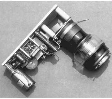
FIG. 8 Vacuum variable capacitor.
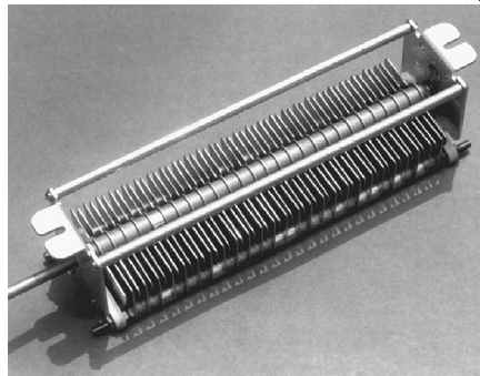
FIG. 7 Transmitting air variable capacitor.
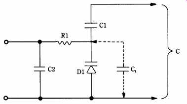
FIG. 9 Variable-capacitance diode (varactor) in a typical circuit.
Solid-state capacitors
One of the problems with variable capacitors is that they are large, bulky things (look at all the photos) that must be mechanically operated. Modern electronic circuits, including most radios today, are electrically tuned using a varicap diode for the capacitor function. These "capacitors" operate because the junction capacitance (Ct) of a PN junction diode is a function of the reverse bias voltage applied across the diode. The varicap (a.k.a. "varactor") is therefore a variable capacitor in which the capacitor is a function of an applied voltage. Maximum capacitances run from 15 to 500 pF, depending on the type.
FIG. 9 shows the usual circuit for a varicap diode. D1 is the varactor, and capacitor C1 is a dc-blocking capacitor. Normally, the value of C1 is set many times higher than the capacitance of the diode. The total capacitance is as follows:
C = C1 x Ct/ [C1 + Ct] (eqn. 1)
Capacitor C1 will affect the total capacitance only negligibly if C1 > Ct.
The control circuit for the varactor is series current-limiting resistor R1. This resistor is typically 10 to 470 k-ohm. The shunt capacitor (C2) is used to decouple RF from the circuit from getting to other circuits and noise signals from other circuits from affecting the capacitor.
Varactors come in several different standard diode packages, including the two terminal "similar to 182" package shown in FIG. 10. Some variants bevel the edge of the package to denote which is the cathode. In other cases, the package style will be like other forms of diode. Varactors are used in almost every form of diode pack age, up to and including the package used for 50- to 100-A stud-mounted rectifier diodes.
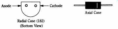
FIG. 10 Typical varactor cases.
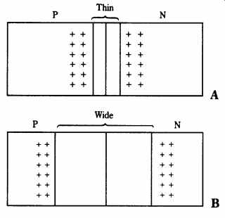
FIG. 11 Varactor diode operation. (A) Thin depletion zone means maximum capacitance;
(B) wider depletion zone means less capacitance.
How do varactors work?
Varactors are specially made PN junction diodes that are designed to enhance the control of the PN junction capacitance with a reverse bias voltage. FIG. 11 shows how this capacitance is formed. A PN junction consists of P- and N-type semi-conductor material placed in juxtaposition with each other, as shown in FIG. 11.
When the diode is forward-biased, the charge carriers (electrons and holes) are forced to the junction interface, where positively charged holes and negatively charged electrons annihilate each other (causing a current to flow). But under re verse bias situations (e.g., those shown in FIG. 11), the charges are drawn away from the junction interface.
FIG. 11A shows the situation where the reverse bias is low. The charge carriers are drawn only a little way from the junction, creating a thin insulating depletion zone. This zone is an insulator between the two charge-carrying P- and N-regions, and this situation fulfills the criterion for a capacitor: two conductors separated by an insulator. FIG. 11B shows the situation where the reverse bias is in creased. The depletion zone is increased, which is analogous to increasing the separation between plates.
The varactor is not an ideal capacitor (but then again, neither are "real" capacitors). FIG. 12 shows the equivalent circuit for a varactor. FIG. 12A shows the actual model circuit, and FIG. 12B shows one that is simplified, but nonetheless is valuable to understanding the varactor's operation. The equivalent circuit of FIG. 12B assumes that certain parameter shown in FIG. 12A are negligible.
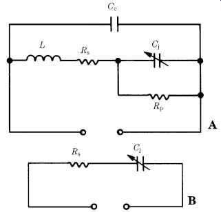
FIG. 12 (A) Equivalent circuit of a varactor diode; (B) simplified circuit.
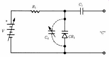
FIG. 13 Varactor diode-control circuit.
FIG. 13 shows a typical test circuit for the varactor. A variable dc voltage is applied as a reverse bias across the diode. A series resistor serves both to limit the current should the voltage exceed the avalanche or zener points (which could destroy the diode) and also to isolate the diode from the rest of the circuitry. Without a high-value resistor (10 to 470 k-ohm is the normal range; 100 k-ohm is typical) in series with the dc supply, stray circuit capacitances and the power-supply output capacitance would swamp the typically low value of varactor capacitance. The capacitor at the output (C1) is used to block the dc from affecting other circuits or the dc in other circuits from affecting the diode. The value of this capacitor must be very large in order to prevent it from affecting the diode capacitance (Cd).
Varactor-tuning voltage sources
The capacitance of a varactor is a function of the applied reverse bias potential. Because of this, it is essential that a stable, noise-free source of bias is provided. If the diode is used to tune an oscillator, for ex ample, frequency drift will result if the dc potential is not stable. Besides ordinary dc drift, noise affects the operation of varactors. Anything that varies the dc voltage applied to the varactor will cause a capacitance shift.
Electronic servicers should be especially wary of varactor-tuned circuits in which the tuning voltage is derived from the main regulated power supply without an intervening regulator that serves only the tuning voltage input of the oscillator.
Dynamic shifts in the regulator's load, variations in the regulator voltage, and other problems can create local oscillator drift problems that are actually power-supply problems and have nothing at all to do with the tuner (despite the apparent symptoms).
The specifications for any given varactor are given in two ways. First is the nominal capacitance taken at a standard voltage (usually 4 Vdc, but 1 and 2 Vdc are also used). The other is a capacitance ratio expected when the dc reverse bias voltage is varied from 2 to 30 Vdc (whatever the maximum permitted applied potential is for that diode). Typical is the NTE replacement line type 614. According to the NTE Service Replacement Guide and Cross-Reference, the 614 has a nominal capacitance of 33 pF at 4 Vdc reverse bias potential and a "C2/C30" capacitance ratio of 3:1.
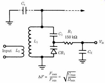
FIG. 14 Varactor diode-tuned circuit.
Varactor applications
Varactors are electronically variable capacitors. In other words, they exhibit a variable capacitance that is a function of a reverse bias potential. This phenomenon leads to several common applications in which capacitance is a consideration. FIG. 14 shows a typical varactor-tuned LC tank circuit. The link-coupled inductor (L2) is used to input RF to the tank when the circuit is used for RF amplifiers (etc.). The principal LC tank circuit consists of the main inductor (L1) and a capacitance made up from the series equivalent of C1 and varactor CR1. In addition, you must also take into account the stray capacitance (Cs) that exists in all electronic circuits. The blocking capacitor and series-resistor functions were covered in the preceding paragraphs. Capacitor C2 is used to filter the tuning voltage, Vin.
Because the resonant frequency of an LC-tuned tank circuit is a function of the square root of the inductance-capacitance product, we find that the maximum/minimum frequency of the varactor-tuned tank circuit varies as the square root of the capacitance ratio of the varactor diode. This value is the ratio of the capacitance at minimum reverse bias over capacitance at maximum reverse bias. A consequence of this is that the tuning characteristic curve (voltage vs frequency) is basically a parabolic function.
Note and Warning!
Cleaning Variable Capacitors
The main tuning capacitors in old radios are often full of crud, grease, and dust.
Similarly, ham radio operators working the hamfest circuit looking for linear amplifier and antenna tuner parts often find just what they need, but the thing is all gooped-up. Several things can be done about it. First, try using dry compressed air.
It will remove dust, but not grease. Aerosol cans of compressed air can be bought from a lot of sources, including automobile parts stores and photography stores.
Another method, if you have the hardware, is to ultrasonically clean the capacitor. The ultrasonic cleaner, however, is expensive; unless you have one, do not rush out to lay down the bucks.
Still another way is to use a product, such as Birchwood Casey Gun Scrubber.
This product is used to clean firearms and is available in most gun shops. Firearms goop-up because gun grease, oil, unburned powder, and burned powder residue combine to create a crusty mess that is every bit as hard to remove as capacitor gunk. A related product is the de-gunking compound used by auto mechanics.
At one time, carbon tetrachloride was used for this purpose-- and you will see it listed in old radio books. However, carbon tet is now well-recognized as a health hazard. DO NOT USE CARBON TETRACHLORIDE for cleaning, despite the advice to the contrary found in old radio books.