AMAZON multi-meters discounts AMAZON oscilloscope discounts
Inductors and capacitors are the principal components used in RF tuning circuits.
The resonant frequency of a tank circuit is the frequency to which the inductor- capacitor combination is tuned and is found from:
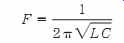
(eqn. 1)
or, if either the inductance (L) or capacitance (C) is known or preselected then the other can be found by solving Eq. (eqn. 1) for the unknown, or:
(eqn. 2) and (eqn. 3)
In all three equations, L is in henrys, C is in farads, and F is in hertz (don't forget to convert values to microhenrys and picofarads after calculations are made).
Capacitors are easily obtained in a wide variety of values. But tuning inductors are either unavailable or are available in other people's ideas of what you need. As a result, it is often difficult to find the kinds of parts that you need. This section will look at how to make your own slug-tuned adjustable inductors, RF transformers, and IF transformers (yes, you can build your own IF transformers).
Tuning inductors can be either air-, ferrite-, or powdered-iron-core coils. The air-core coils are not adjustable unless either an expensive roller-contact mechanism or clumsy taps on the winding of the coil are provided. However, the ferrite- and powdered-iron slug-tuned core coils are adjustable.
FIG. 1 Variable inductor on open coil form.
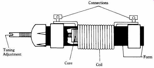
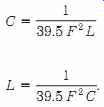
FIG. 1 shows one form of slug-tuned adjustable coil. The form is made
of plastic, phenolic, fiberglass, nylon, or ceramic materials and is internally
threaded.
The windings of the coil (or coils in the case of RF/IF transformers) are wound onto the form. The equation for calculating the inductance of a single-layer air-core coil was discussed in Section 2. For non-air-core coils, the inductance is multiplied by a factor that is determined by the properties of the core material.
The tuning slug is a ferrite- or powdered-iron-core coil that mates with the internal threads in the coil form. A screwdriver slot or hex hole in either (or both) end allows you to adjust it. The inductance of the coil depends on how much of the core is inside the coil windings.
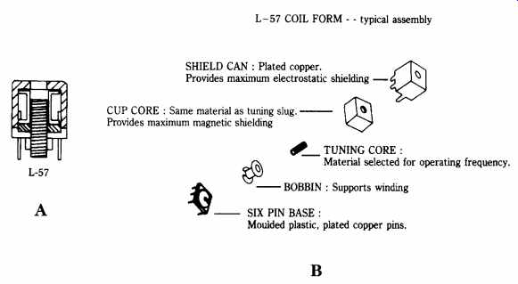
FIG. 2 Shielded slug-tuned variable inductor.
Amidon Associates coil system
It was once difficult to obtain coil forms to make your own project inductors.
Amidon Associates Inc. makes a series of slug-tuned inductor forms that can be used to make any-value coil that you are likely to need. FIG. 2A shows an Amidon form, and FIG. 2B shows an exploded view.
Table 1 gives the type numbers, frequency ranges (in megaHertz), and other specifications for the coil forms made by Amidon. Three sizes of coil form are offered. The L-33s are 0.31" square and 0.40" high, the L-43s are 0.44" square and 0.50" high, and the L-57s are 0.56" square and 0.50" high. The last number (e.g., _1, _6, _10) in each type number indicates the type of material, which in turn translates to the operating frequency range (see Table 1). Now, see how the coil forms are used.
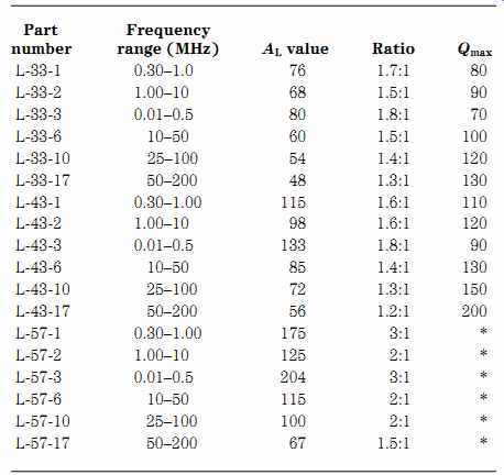
Table 1. Amidon coil form specifications
Determine the required inductance from Eq. (eqn. 3). For an experiment to see how this coil system works, I decided to build a 15-MHz WWV converter that reduced the WWV radio station frequency to an 80- to 75-m ham-band frequency.
Thus, I needed a circuit that would tune 15 MHz. It is generally a good idea to have a high capacitance-to-inductance ratio in order to maintain a high Q factor. I selected a 56-pF NPO capacitor for the tuned circuit because it is in the right range, and a dozen or so were in my junk box. According to Eq. (eqn. 3), therefore, I needed a 2-uH inductor.
To calculate the number of turns (N) required to make any specific inductance, use the following equation:
where L = inductance in microhenrys (uH)
N = the number of turns.
The AL factor is a function of the properties of the core materials and is found in Table 1; the units are microhenrys per 100 turns (uH/100 turns). In my case, I selected an L-57-6, which covers the correct frequency range and has an AL value of 115 uH/100 turns. According to Eq. (eqn. 4), therefore, I need 14 turns of wire.
The coil is wound from no. 26 to no. 32 wire. Ideally, Litz wire is used, but that is both hard to find and difficult to solder. For most projects ordinary enamel-coated magnet wire will suffice. A razor knife (such as X-acto) and soldering iron tip can be used to remove the enamel from the ends of the wire. Because the forms are small, I recommend using the no. 32 size.
Winding the coil can be a bit tricky if your vision needs augmentation as much as mine. But, using tweezers, needlenose pliers, and a magnifying glass on a stand made it relatively easy. FIG. 3 shows the method for winding a coil with a tapped winding. Anchor one end of the wire with solder on one of the end posts and use this as the reference point. In my case, I wanted a 3-turn tap on the 14-turn coil, so I wound 3 turns then looped the wire around the center post. After this point was soldered, the rest of the coil was wound and then anchored at the remaining end post. A dab of glue or clear fingernail polish will keep the coil windings from moving.
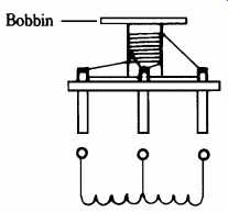
FIG. 3 Construction of a custom coil using FIG. 2.
If you make an RF/IF transformer, then there will be two windings. Try to separate the primary and secondary windings if both are tuned. If one winding is not tuned, then simply wind it over the "cold" (i.e., ground) end of the tuned winding- no separation is needed.
The Amidon coil forms are tight, but they do have sufficient space for very small disk ceramic capacitors inside. The 56-pF capacitors that I selected fit nicely inside the shielded can of the coil, so I elected to place it there. Thus, I've basically made a 15-MHz RF/IF transformer.
After constructing the 15-MHz RF coil, I tested it and found that the slug tuned the coil to 15 MHz with a nice tolerance on either side of the design resonant frequency. It worked! Although slug-tuned inductors are sometimes considered a bit beyond the hobbyist or ham, that is not actually true. The Amidon L-series coil forms can easily be used to make almost any inductor that you are likely to need.
Making your own toroid-core inductors and RF transformers
A lot of construction projects intended for electronic hobbyists and amateur radio operators call for inductors or radio-frequency (RF) transformers wound on toroidal cores. A toroid is a doughnut-shaped object, i.e., a short cylinder (often with rounded edges) that has a hole in the center (see FIG. 4). The toroidal shape is desirable for inductors because it permits a relatively high inductance value with few turns of wire, and, perhaps most important, the geometry of the core makes it self shielding. That latter attribute makes the toroid inductor easier to use in practical RF circuits. Regular solenoid-wound cylindrical inductors have a magnetic field that goes outside the immediate vicinity of the windings and can thus intersect nearby inductors and other objects. Unintentional inductive coupling can cause a lot of serious problems in RF electronic circuits so they should be avoided wherever possible.
The use of a toroidal shape factor, with its limited external magnetic field, makes it possible to mount the inductor close to other inductors (and other components) without too much undesired interaction.
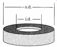
FIG. 4 (A) Trifilar wound transformer circuit; (B) actual windings; (C) glue
or silicone seal is used to hold the ends of the windings.
Materials used in toroidal cores
Toroid cores are available in a variety of materials that are usually grouped into two general classes: powdered iron and ferrite. These groups are further subdivided.
Powdered-iron materials
Powdered-iron cores are available in two basic formulations: carbonyl irons and hydrogen-reduced irons. The carbonyl materials are well-regarded for their temperature stability; they have permeability (_) values that range from 1 deg. to about 35 deg.
The carbonyls offer very good Q values to frequencies of 200 MHz. Carbonyls are used in high-power applications as well as in variable-frequency oscillators and wherever temperature stability becomes important. However, notice that no powdered-iron material or ferrite is totally free of temperature variation, so oscillators using these cores must be temperature compensated for proper operation. The hydrogen-reduced iron devices offer permeabilities up to 90 deg., but are lower Q than carbonyl devices. They are most used in electromagnetic interference (EMI) filters.
The powdered-iron materials are the subject of Table 2.
----------------
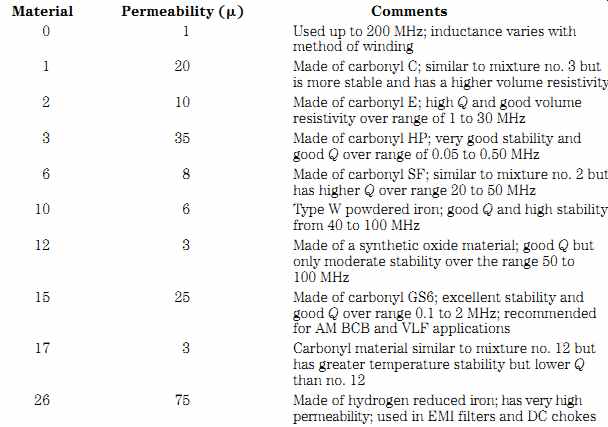
Table 2. Powdered-iron core materials Material Permeability (_) Comments
0 1 Used up to 200 MHz; inductance varies with method of winding
1 20 Made of carbonyl C; similar to mixture no. 3 but is more stable and has a higher volume resistivity 2 10 Made of carbonyl E; high Q and good volume resistivity over range of 1 to 30 MHz 3 35 Made of carbonyl HP; very good stability and good Q over range of 0.05 to 0.50 MHz 6 8 Made of carbonyl SF; similar to mixture no. 2 but has higher Q over range 20 to 50 MHz 10 6 Type W powdered iron; good Q and high stability from 40 to 100 MHz
12 3 Made of a synthetic oxide material; good Q but only moderate stability over the range 50 to 100 MHz 15 25 Made of carbonyl GS6; excellent stability and good Q over range 0.1 to 2 MHz; recommended for AM BCB and VLF applications 17 3 Carbonyl material similar to mixture no. 12 but has greater temperature stability but lower Q than no. 12
26 75 Made of hydrogen reduced iron; has very high permeability; used in EMI filters and DC chokes
----------------
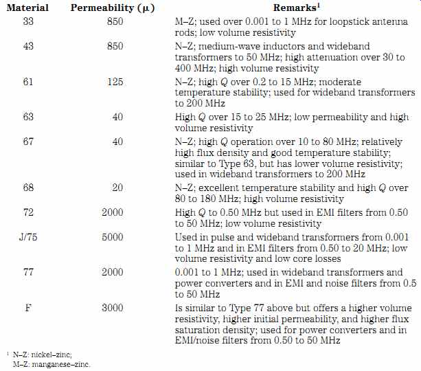
Table 3. Ferrite materials
Material Permeability (u) Remarks
33 850 M-Z; used over 0.001 to 1 MHz for loopstick antenna rods; low volume resistivity
43 850 N-Z; medium-wave inductors and wideband transformers to 50 MHz; high attenuation over 30 to 400 MHz; high volume resistivity
61 125 N-Z; high Q over 0.2 to 15 MHz; moderate temperature stability; used for wideband transformers to 200 MHz
63 40 High Q over 15 to 25 MHz; low permeability and high volume resistivity
67 40 N-Z; high Q operation over 10 to 80 MHz; relatively high flux density and good temperature stability;
similar to Type 63, but has lower volume resistivity;
used in wideband transformers to 200 MHz
68 20 N-Z; excellent temperature stability and high Q over 80 to 180 MHz; high volume resistivity
72 2000 High Q to 0.50 MHz but used in EMI filters from 0.50 to 50 MHz; low volume resistivity
J/75 5000
Used in pulse and wideband transformers from 0.001 to 1 MHz and in EMI filters from 0.50 to 20 MHz; low volume resistivity and low core losses
77 2000 0.001 to 1 MHz; used in wideband transformers and power converters and in EMI and noise filters from 0.5 to 50 MHz
F 3000 Is similar to Type 77 above but offers a higher volume resistivity, higher initial permeability, and higher flux saturation density; used for power converters and in EMI/noise filters from 0.50 to 50 MHz
1 N-Z: nickel-zinc;
M-Z: manganese-zinc.
--------------
Ferrite materials
The name ferrite implies that the materials are iron-based (they are not), but ferrites are actually grouped into nickel-zinc and manganese-zinc types. The nickel-zinc material has a high-volume resistivity and high Q over the range 0.50 to 100 MHz.
The temperature stability is only moderate, however. The permeabilities of nickel zinc materials are found in the range 125 to 850 u. The manganese-zinc materials have higher permeabilities than nickel-zinc and are on the order of 850 to 5000 u.
Manganese-zinc materials offer high Q over 0.001 to 1 MHz. They have low volume resistivity and moderate saturation flux density. These materials are used in switching power supplies from 20 to 100 kHz and for EMI attenuation in the range 20 to 400 MHz. See Table 3 for information on ferrite materials.
Toroid-core nomenclature
Although there are several different ways to designate toroidal cores, the one used by Amidon Associates is perhaps that most commonly found in electronic hobbyist and amateur radio published projects.
Although the units of measure are the English system, which is used in the United States and Canada and formerly in the UK, rather than SI units, their use with respect to toroids seems widespread. The type number for any given core will consist of three elements: xx-yy-zz. The "xx" is a one- or two-letter designation of the general class of material, i.e., powdered iron (xx _ "T") or ferrite (xx _ "TF"). The "yy" is a rounded-off approximation of the outside diameter (o.d. in FIG. 4) of the core in inches; "37" indicates a 0.375" (9.53 mm) core, while "50" indicates a 0.50" (12.7 mm) core. The "zz" indicates the type (mixture) of material. A mixture no. 2 powdered-iron core of 0.50" diameter would be listed as a T-50-2 core. The cores are color-coded to assist in identification.
Inductance of toroidal coils
The inductance of the toroidal core inductor is a function of the permeability of the core material, the number of turns, the inside diameter (i.d.) of the core, the outside diameter (o.d.) of the core, and the height (h) (see FIG. 1) and can be approximated by:
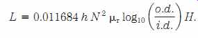
(eqn. 5)
This equation is rarely used directly, however, because toroid manufacturers pro vide a parameter called the AL value, which relates inductance per 100 or 100 turns of wire. Tables 4-4 and 4-5 show the AL values of common ferrite and powdered-iron cores.
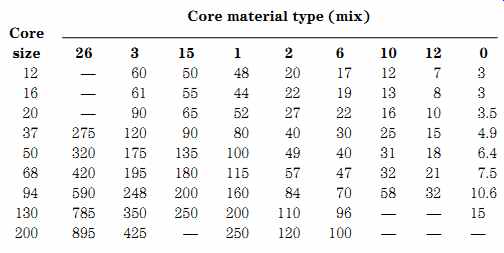
Table 4. Common powdered-iron AL values
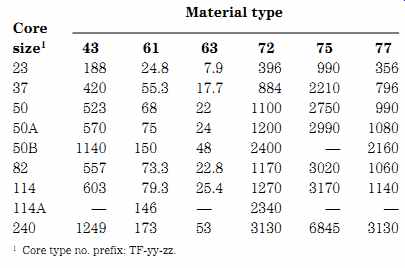
Table 5. Common ferrite-core A values
FIG. 5 Toroid winding styles: (A) distributed; (B) close wound.
Winding toroid inductors
There are two basic ways to wind a toroidal core inductor: distributed (Fig. 4 5A) and close-spaced (FIG. 5B). In distributed toroidal inductors, the turns of wire that are wound on the toroidal core are spaced evenly around the circumference of the core, with the exception of a gap of at least 30 deg. between the ends (see FIG. 5A).
The gap ensures that stray capacitance is kept to a minimum. The winding covers 270 deg. of the core. In close winding (FIG. 5B), the turns are made so that adjacent turns of wire touch each other. This practice raises the stray capacitance of the winding, which affects the resonant frequency, but can be done in many cases with little or no ill effect (especially where the capacitance and resonant point shift are negligible, it also provides a means of final adjustment of actual inductance in the circuit as-built.
Calculating the number of turns
As in all inductors, the number of turns of wire determines the inductance of the finished coil. In powdered-iron cores, the AL rating of the core is used with fair confidence to predict the number of turns needed.
For powdered-iron cores:
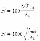
(eqn. 6) For ferrite cores:
(eqn. 7)
where:
N = the number of turns
LuH = inductance in microhenrys (uH)
LmH = inductance in millihenrys (mH)
AL is a property of the core material.
Building the toroidal device
The toroid core or transformer is usually wound with enameled or formvar-insulated wire. For low-powered applications (receivers, VFOs, etc.) the wire will usually be no. 22 through no. 36 (with no. 26 being very common) AWG. For high-power applications, such as transmitters and RF power amplifiers, a heavier grade of wire is needed. For high-power RF applications, no. 14 or no. 12 wire is usually specified, although wire as large as no. 6 has been used in some commercial applications.
Again, the wire is enameled or formvar-covered insulated wire.
In the high-power case, it is likely that high voltages will exist. In high-powered RF amplifiers, such as used by amateur radio operators in many countries, the potentials present across a 50-ohm circuit can reach hundreds of volts. In those cases, it is common practice to wrap the core with a glass-based tape, such as Scotch 27.
High-powered applications also require a large-area toroid rather than the small toroids that are practical at lower power levels. Cores in the FT-150-zz to FT-240-zz or T-130-zz to T-500-zz are typically used. In some high-powered cases, several identical toroids are stacked together and wrapped with tape to increase the power handling capacity. This method is used quite commonly in RF power amplifier and antenna tuner projects.
Binding the wires
It sometimes happens that the wires making up the toroidal inductor or trans former become loose. Some builders prefer to fasten the wire to the core using one of the two methods shown in FIG. 6. FIG. 6A shows a dab of glue, silicone adhesive, or the high-voltage sealant Glyptol (sometimes used in television receiver high-voltage circuits) to anchor the end of the wire to the toroid core.
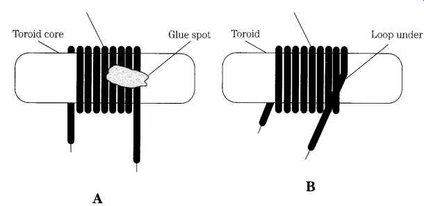
FIG. 6 Methods for fastening the wire on a toroid winding: (A) glue spot and
(B) "tuck under" method.
Other builders prefer the method shown in FIG. 6B. In this method, the end of the wire is looped underneath the first full turn and pulled taut. This method will effectively anchor the wire, but some say it creates an anomaly in the magnetic situation that might provoke interactions with nearby components. In my experience, that situation is not terribly likely, and I use the method regularly with no observed problems thus far.
When the final coil is ready, and both the turns count and spacing are adjusted to yield the required inductance, the turns can be anchored to the coil placed in ser vice. A final sealant method is to coat the coil with a thin layer of clear lacquer, or "Q-dope" (this product is intended by its manufacturer as an inductor sealant).
Mounting the toroidal core
Toroids are a bit more difficult to mount than solenoid-wound coils (cylindrical coils), but the rules that one must follow are not as strict. The reason for loosening of the mounting rules is that the toroid, when built correctly, is essentially self shielding, so less attention (not no attention!) can be paid to the components that surround the inductor. In the solenoid-wound coil, for example, the distance be tween adjacent coils and their orientation is important. Adjacent coils, unless well shielded, must be placed at right angles to each other to lessen the mutual coupling between the coils. However, toroidal inductors can be closer together and either coplanar or adjacent planar can be placed with respect to each other. Although some spacing must be maintained between toroidal cores (the winding and core manufacture not being perfect), the required average distance can be less than for solenoid wound cores.
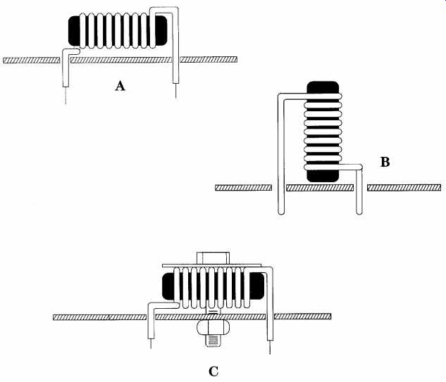
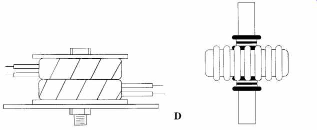
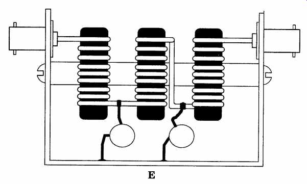
FIG. 7 (A) Flat mounting; (B) on-end mounting; (C) secured mounting (use nylon
machine screws); (D) mounting high-power or high-voltage toroidal inductors
or transformers; (E) suspending toroid inductors on a dowel; (F) mounting
method for a "single-turn primary" trans former in RF watt-meters
or VSWR meters.
Mechanical stability of the mounting is always a consideration for any coil (in deed, any electronic component). For most benign environments, the core can be mounted directly to a printed wiring board (PWB) in the manner of Figs. 7A and 7B. In FIG. 7A, the toroidal inductor is mounted flat against the board; its leads are passed through holes in the board to solder pads underneath. The method of FIG. 7B places the toroid at right angles to the board, but it still uses the leads soldered to copper pads on the PWB to anchor the coil. It is wise to use a small amount of RTV silicone sealant or glue to held the coil to the board once it is found to work satisfactorily.
If the environment is less benign with respect to vibration levels, then a method similar to FIG. 7C can be used. Here, the toroid is fastened to the PWB with a set of nylon machine screw and nut hardware and a nylon or fiber washer. In high-powered antenna tuning units, it is common to see an arrangement similar to that in FIG. 7D.
In this configuration, several toroidal cores are individually wrapped in glass tape, then the entire assembly is wrapped as a unit with the same tape. This assembly is mounted between two insulators, such as plastics, ceramic, or fiberboard, which are held together as a "sandwich" by a nylon bolt and hex nut.
FIG. 7E shows a method for suspending toroidal cores in a shielded enclosure. I've used this method to make five-element low-pass filters for use in my basement laboratory. The toroidal inductors are mounted on a dowel, which is made of some insulating material, such as wood, plastic, plexiglass, Lexan, or other synthetic.
If the dowel is sized correctly, then the inductors will be a tight slip fit and there will be no need for further anchoring. Otherwise, a small amount of glue or RTV silicone sealant can be used to stabilize the position of the inductor.
Some people use a pair of undersized rubber grommets over the dowel, one pressed against either side of the inductor (see inset to FIG. 7E). If the grommets are taut enough, then no further action is needed. Otherwise, they can be glued to the rod.
A related mounting method is used to make current transformers in home made RF power meters (FIG. 7F). In this case, a rubber grommet is fitted into the center of the toroid, and a small brass or copper rod is passed through the center hole of the grommet. The metal rod serves as a one-turn primary winding. A sample of the RF current flowing in the metal rod is magnetically coupled to the secondary winding on the toroid, where it can be fed to an oscilloscope for display or rectified, filtered, and displayed on a dc current meter that is calibrated in watts or VSWR units.
Torodial RF transformers
Both narrowband-tuned and broadband RF transformers can be accommodated by toroidal powdered-iron and ferrite cores. The schematic symbols used for trans formers are shown in FIG. 8. These symbols are largely interchangeable and are all seen from time to time. In FIG. 8A, the two windings are shown adjacent to each other, but the core is shown along only one of them. This method is used to keep the drawing simple and does not imply in any way that the core does not affect one of the windings. The core can be represented either by one or more straight lines, as shown, or by dotted lines. The method shown in FIG. 8B is like the conventional transformer representation in which the windings are juxtaposed opposite each other with the core between them. In FIG. 8C, the core is extended and the two windings are along one side of the core bars.
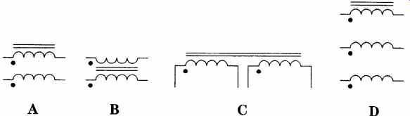
FIG. 8 Transformer schematic styles.
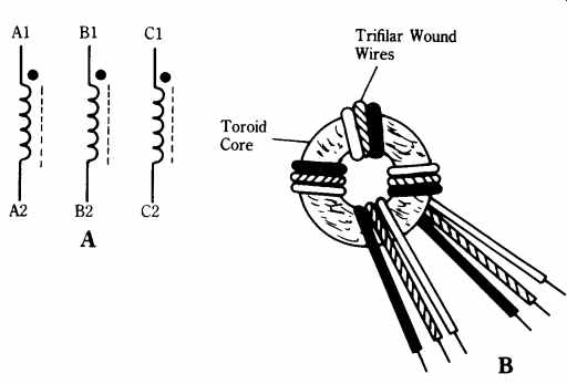
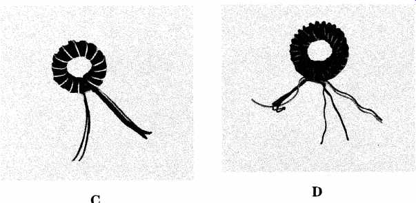
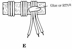
FIG. 9 Trifilar wound transformer: (A) circuit symbol; (B) winding details;
(C) using parallel wires; (D) using twisted wires; and (E) glue spot for
securing windings.
In each of the transformer representations of FIG. 8, dots are on the windings.
These dots show the "sense" of the winding and represent the same end of the coils.
Thus, the wires from two dotted ends are brought to the same location, and the two coils are wound in the same direction. Another way of looking at it is that if a third winding were used to excite the core from an RF source, the phase of the signals at the dot end will be the same; the phase of the signal at the undotted ends will also be the same, but will be opposite that of the dotted ends.
I was once questioned by a reader concerning the winding protocol for toroidal transformers, as shown in books and magazine articles. My correspondent included a partial circuit (FIG. 9A) as typical of the dilemma. The question was How do you wind it? and a couple of alternative methods were proposed. At first I thought it was a silly question because the answer was obvious, and then I realized that perhaps I was wrong; to many people, the answer was not that obvious. The answer to this question is that all windings are wound together in a multi-filar manner.
Because there are three windings, in this case, we are talking about trifilar windings. FIG. 9B shows the trifilar winding method. For the sake of clarity, I have colored all the three wires differently so that you can follow it. This practice is also a good idea for practical situations. Because most of my projects use nos. 26, 28, or 30 enameled wire to wind coils, I keep three colors of each size on hand and wind each winding with a different color. That makes it a whole lot easier to identify which ends go with each other.
The dots in the schematic and on the pictorial are provided to identify one end of the coil windings. Thus, the dot and no-dot ends are different from each other; in circuit operation, it usually makes a difference which way the ends are connected into the circuit (the issue is signal phasing).
Figures 9C and 9D shows two accepted methods for winding a multifilar coil on a toroidal core. FIG. 9C is the same method as in FIG. 9B, but on an actual toroid instead of a pictorial representation. The wires are laid down parallel to each other as shown previously. The method in FIG. 9D uses twisted wires. The three wires are chucked up in a drill and twisted together before being wound on the core.
With one end of the three wires secured in the drill chuck, anchor the other end of the three wires in something that will hold it taut. I use a bench vise for this purpose.
Turn the drill on the slow speed and allow the wires to twist together until the de sired pitch is achieved.
Be very careful when performing this operation. If you don't have a variable speed electric drill (so that it can be run at very low speeds), then use an old fashioned manual hand drill. If you use an electric drill, wear eye protection. If the wire breaks or gets loose from its mooring, it will whip around wildly until the drill stops. That whipping wire can cause painful welts on your skin, and it can easily cause permanent eye damage.
Of the two methods for winding toroids, the method shown in Figs. 9B and 9C is preferred. When winding toroids, at least those of relatively few windings, pass the wire through the doughnut hole until the toroid is about in the middle of the length of wire. Then, loop the wire over the outside surface of the toroid and pass it through the hole again. Repeat this process until the correct number of turns are wound onto the core. Be sure to press the wire against the toroid form and keep it taut as you wind the coils.
Enameled wire is usually used for toroid transformers and inductors, and that type of wire can lead to a problem. The enamel can chip and cause the copper conductor to contact the core. On larger cores, such as those used for matching trans formers and baluns used at kilowatt power levels, the practical solution is to wrap the bare toroid core in a layer of fiberglass packing tape. Wrap the tape exactly as if it were wire, but overlap the turns slightly to ensure that the entire circumference of the core is covered.
On some projects, especially those in which the coils and transformers use very fine wire (e.g., no. 30), I have experienced a tendency for the wire windings to unravel after the winding is completed. This problem is also easily curable. At the ends of the windings place a tiny dab of rubber cement or RTV silicone sealer (see FIG. 5E).