AMAZON multi-meters discounts AMAZON oscilloscope discounts
<< cont'd. from part 1
Conventional RF transformers
One of the principal uses of transformers in RF circuits is impedance transformation. When the secondary winding of a transformer is connected to a load impedance, the impedance seen "looking into" the primary will be a function of the load impedance and the turns ratio of the transformer (see FIG. 10A). The relationship is:

(eqn. 8)
With the relationship of Eq. (eqn. 8), you can match source and load impedances in RF circuits.
Example
Assume that you have a 3- to 30-MHz transistor RF amplifier with a base input impedance of 4 ohm (Zs), and that transistor amplifier has to be matched to a 50-ohm source impedance (Zp), as shown in FIG. 10B. What turns ratio is needed to effect the impedance match? Let's calculate:
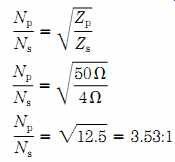
(eqn. 9)
A general design rule for the value of inductance used in transformers is that the inductive reactance at the lowest frequency must be 4 times (4x) the impedance connected to that winding. In the case of the 50-ohm primary of this transformer, the inductive reactance of the primary winding should be 4 x 50 = 200 ohm. The inductance should be:
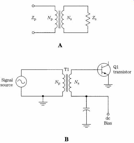
FIG. 10 (A) A transformer with primary and secondary labels; (B) typical transformer
circuit with transistor load.
Now that you know that a 10.6-uH inductance is needed, you can select a toroidal core and calculate the number of turns needed. The T-50-2 (RED) core covers the correct frequency range and is of a size that is congenial to easy construction.
The T-50-2 (RED) core has an AL value of 49, so the number of turns required is as follows:
The number of turns in the secondary must be such that the 3.53 : 1 ratio is pre served when 47 turns are used in the primary:
If you wind the primary with 47 turns and the secondary with 13 turns, then you can convert the 4-ohm transistor base impedance to the 50-ohm systems impedance.
Example
A beverage antenna can be constructed for the AM broadcast band (530 to 1700 kHz). By virtue of its construction and installation, it exhibits a characteristic impedance, Zo, of 600 ohm. What is the turns ratio required of a transformer at the feed end (FIG. 11) to match a 50-ohm receiver input impedance?
FIG. 11 Coupling transformer used to feed a Beverage antenna.
The secondary requires an inductive reactance of 4 ohm 600 ohm_ 2400 ohm. To obtain this inductive reactance at the lowest frequency of operation requires an inductance of:
Checking a table of powdered-iron toroid cores, you will find that the _15 (RED/WHT) mixture will operate over 0.1 to 2 MHz (see Table 6.). Selecting a T-106-15 (Red/White) core provides an AL value of 345. The number of turns required to create an inductance of 721 uH is:
The primary winding must have:
Winding this transformer, as designed, should provide adequate service.
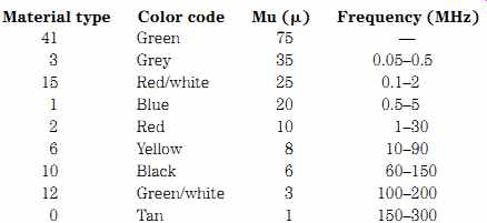
Table 6. Properties of powdered-iron core types
Ferrite and powdered-iron rods
Ferrite rods (FIG. 12A) are used in the low-frequency medium wave, AM broadcast band, and LF/VLF receivers to form "loopstick" antennas. These antennas are often used in radio-direction finders because they possess a "figure-8" reception pattern that counterposes two deep nulls with a pair of main lobes.
Another application of ferrite rods is to make balun transformers (FIG. 12B) or filament transformers in vacuum-tube high-power RF amplifiers. Ferrite rod inductors are also used in any application, up to about 10 MHz, where a high inductance is needed.
Two permeability figures are associated with the ferrite rod, but only one of them is easily available (see Table 7): the initial permeability. This figure is used in the equations for inductance. The effective permeability is a little harder to pin down and is dependent on such factors as (a) the length/diameter ratio of the rod, (b) lo cation of the coil on the rod (centered is most predictable), (c) the spacing between turns of wire, and (d) the amount of air space between the wire and the rod. In general, maximizing effective AL and inductance requires placing the coil in the center of the rod. The best Q, on the other hand, is achieved when the coil runs nearly the entire length of the rod.
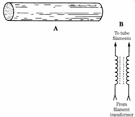
FIG. 12 (A) Ferrite rod; (B) filament transformer RF choke.
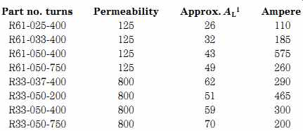
Table 7. Properties of some common ferrite rods
Several common ferrite rods available from Amidon Associates are shown in Table 7. The "R" indicates "rod" while the number associated with the "R" (e.g., R61) indicates the type of ferrite material used in the rod. The following numbers (e.g., 025) denote the diameter (025 _ 0.25_, 033 _ 0.33_, and 050 _ 0.50_); the length of the rod is given by the last three digits (200 _ 2_, 400 _ 4_, and 750 _ 7.5_.)
The Type 61 material is used from 0.2 to 10 MHz, and the Type 33 material is used in VLF applications.
In some cases, the AL rating of the rod will be known, and in others, only the permeability (u) is known. If either is known, you can calculate the inductance produced by any given number of turns.
For the case where the AL is known:
(eqn. 10)
For the case where _ is known:
(eqn. 11)
where
Np is the number of turns of wire
_ is the core permeability
Ae is the cross-sectional area of the core (cm^2) le is the length of the rod's flux path (cm)
Example
Find the number of turns required on an R61-050-750 ferrite rod to make a 220-uH inductor for use in the AM receiver with a 10- to 365-pF variable capacitor.
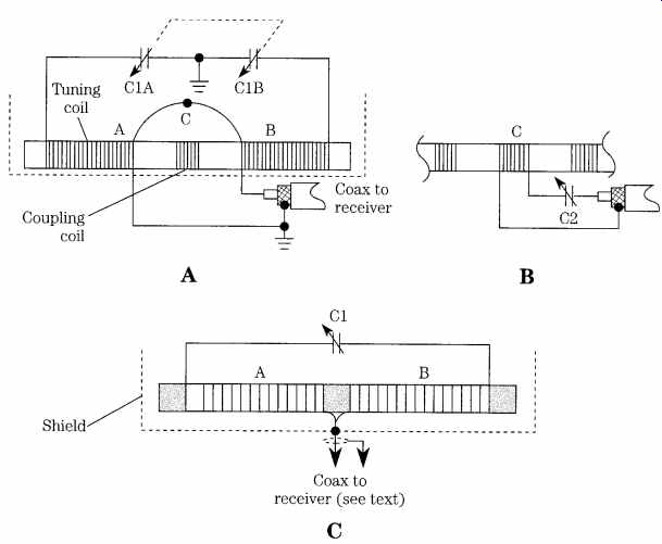
FIG. 13 Loopstick antenna: (A) overall circuit for doubled-tuned winding; (B)
tuning the coupling loop; and (C) singled tuned variety.
Solution
Solving Eq. (eqn. 11) for N:
FIG. 13 shows several popular ways for ferrite rod inductors to be wound for service as loopstick antennas in radio receivers. FIG. 13A shows a transformer circuit in which the main tuned winding is broken into two halves, A and B. These windings are at the end regions of the rod but are connected together in series at the center. The main coils are resonated by a dual capacitor, C1A and C1B. A coupling winding, of fewer turns, is placed at the center of the rod and is connected to the coaxial cable going to the receiver. In some cases, the small coil is also tuned but usually with a series capacitor (see FIG. 13B). Capacitor C2 is usually a much larger value than C1 because the coupling winding has so many fewer turns than the main tuning windings. The antenna in FIG. 13C is a little different. The two halves of the tuning winding are connected together at the center and connected directly to the center conductor of the coaxial cable or to a single downlead. A single capacitor is used to resonate the entire winding (both halves).
Project 1
A radio direction-finding antenna can be used for a number of purposes, only one of which is finding the direction from which a radio signal arrives. Another use is in suppressing co-channel and adjacent-channel interference. This becomes possible when the desired station is in a direction close to right angles from the line be tween the receiver and the desired transmitter. Reduction of the signal strength of the interfering signal is possible because the loopstick antenna has nulls off both ends.
FIG. 14 shows a loopstick antenna mounted in a shielded compartment for radio direction finding. The shield is used to prevent electrical field coupling from nearby sources, such as power lines and other stations, yet doesn't affect the reception of the magnetic field of radio stations. The aluminum can be one-half of an electronic hobbyist's utility box, of appropriate dimensions, or can be built custom from Harry & Harriet Homeowner Do-It-Yourself hardware stores. The loopstick antenna is mounted by nonmetallic cable ties to nylon spacers that are, in turn, fastened to the aluminum surface with nylon hardware.
The number of turns required for the winding can be found experimentally, but starting with the number called for by the preceding formula. The actual number of turns depends in part on the frequency of the band being received and the value of the capacitors used to resonate the loopstick antenna.
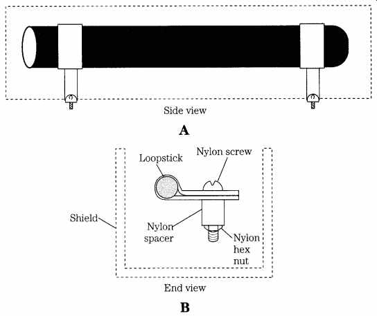
FIG. 14 Mounting the loopstick antenna in a shielded enclosure.
Non-cylindrical air-core inductors
Most inductors used in radio and other RF circuits are either toroidal or sole noid-wound cylindrical. There is, however, a class of inductors that are neither solenoidal nor toroidal. Many loop antennas are actually inductors fashioned into either triangle, square, hexagon, or octagon shapes. Of these, the most common is the square-wound loop coil (FIG. 15). The two basic forms are: flat wound (FIG. 15A) and depth wound (FIG. 15B). The equation for the inductance of these shaped coils is a bit difficult to calculate, but the equation provided by F. W. Grover of the U.S. National Bureau of Standards in 1946 is workable:
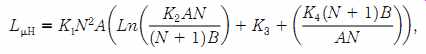
(eqn. 12)
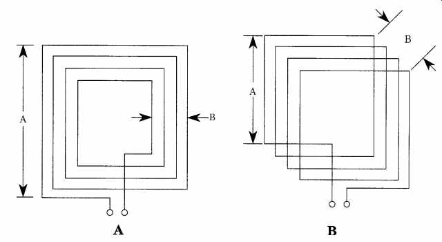
FIG. 15 Inductive-loop direction-finding antenna.
Where:
A is the length of each side in centimeters (cm) B is the width of the coil in centimeters (cm) N is the number of turns in the coil (close wound) K1, K2, K3, and K4 are 0.008, 1.4142, 0.37942, and 0.3333 respectively.
Whenever conductors are placed side by side, as in the case of the loop-wound coil, there is a capacitance between the conductors (even if formed by a single loop of wire, as in a coil). This capacitance can be significant when dealing with radio circuits. The estimate of distributed loop capacitance (in picofarads) for square loops is given by Bramslev as about 60A, where A is expressed in meters (m). The distributed capacitance must be accounted for in making calculations of resonance. Subtract the distributed capacitance from the total capacitance required in order to find the value of the capacitor required to resonate the loop-wound coil.
Binocular- ("balun" or "bazooka") core inductors
The toroidal core has a certain charm because it is easy to use, is predictable, and is inherently self-shielding because of its geometry. But there is another core shape that offers very high inductance values in a small volume. The binocular core (FIG. 16) offers very high AL values in small packages, so you can create very high inductance values without them being excessively large. A binocular core that uses type 43 ferrite, and is about the same weight and size as the T-50-43 (AL _ 523), has an AL value of 2890. Only 8.8 turns are required to achieve 225 uH on this core.
There are actually two different types of binocular core in FIG. 16. The Type 1 binocular core is shown in FIG. 16A. It is larger than the Type 2 (FIG. 16B) and has larger holes. It can, therefore, be used for larger-value inductors and transformers. The Type 2 core can be considered as a two-hole ferrite bead.
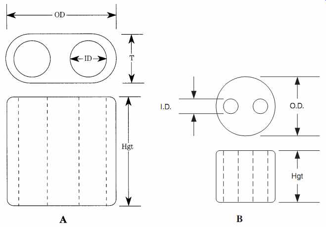
FIG. 16 Bazooka balun cores: (A) Type 1 and (B) Type 2.
Table 8 shows several popular-sized binocular cores and their associated AL values. The center two digits of each part number is the type of ferrite material used to make the core (e.g., BN-xx-202), and the last digits refer to the size and style of the core.
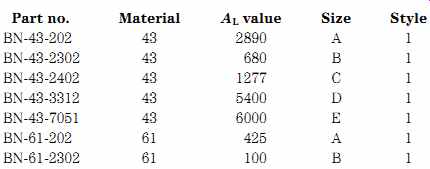
Table 8. Binocular cores
Three different ferrite materials are commonly used in binocular cores. The type 43 material is a nickel-zinc ferrite and has a permeability of 850. It is used for wide band transformers up to 50 MHz and has high attenuation, from 30 to 400 MHz. It can be used in tuned RF circuits from 10 to 1000 kHz. The type 61 material is also nickel-zinc and has a permeability of 125. It offers moderate to good thermal stability and a high Q over the range 200 kHz to 15 MHz. It can be used for wideband transformers up to 200 MHz. The type 73 material has a permeability of 2500 and offers high attenuation from 500 kHz to 50 MHz.
The binocular core can be used for a variety of different RF inductor devices.
Besides the single, fixed inductor, it is also possible to wind conventional transformers and balun transformers of various types on the core.
FIG. 17 shows Type 1 binocular cores wound in various ways. The normal manner of winding the turns of the inductor is shown in FIG. 17A; the wire is passed from hole to hole around the central wall between the holes. The published AL values for each core are based on this style of winding, and it is the most commonly used.
An edge-wound coil is shown in FIG. 17B. In this coil, the turns are wound around the outside of the binocular core. To check the difference, I wound a pair of BN-43-202 cores with 10 turns of no. 26 wire; one in the center (FIG. 17A) and one around the edge (FIG. 17B). The center-wound version produced 326 uH of inductance, and the edge-wound version produced 276 uH with the same number of turns.
Counting the turns on a binocular core is a little different than you might expect.
A single U-shaped loop that enters and exits the core on the same side (FIG. 17C) counts as one turn. When the wire is looped back through a second time (Fig. 7D), there are two turns.
Winding the binocular core
Some people think that it is easier to use these cores than toroids, and after spending a rainy weekend winding LF and AM BCB coils (after pumping groundwater out of the basement workshop!), I am inclined to agree partially. The "partially" means that they are easier to work than toroids if you do it correctly. It took me some experimenting to figure out a better way than holding the core in one hand and the existing wires already on the core in another hand and then winding the remaining coils with a third hand. Not being a Martian, I don't have three hands, and my "Third Hand" bench tool didn't seem to offer much help. Its alligator clip jaws were too coarse for the no. 36 enameled wire that I was using for the windings. So, enter a little "mother of invention" ingenuity (it's amazing how breaking a few wires can focus one's attention on the problem). In fact, I came up with two related methods be tween gurgles of my portable sump pump.
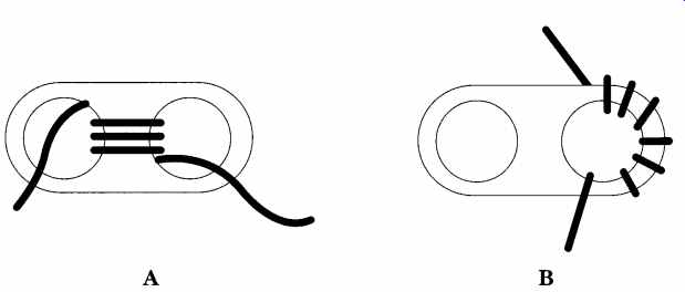
FIG. 17 Winding style for Bazooka balun cores: (A) through the center; (B)
around the edge (less-predictable inductance); (C) single turn winding (note:
no doubling back); and (D) two turn winding.
The first method is shown in FIG. 18. The binocular core is temporarily affixed to a stiff piece of cardboard stock such as a 5 x 7" card or a piece cut from the stiffener used in men's shirts at the laundry. The cardboard is taped to the work surface, and the core is taped to the cardboard. One end of the wire that will be used for the winding is taped to the cardboard with enough leader to permit working the end of the coil once it is finished (2 to 3"). Pass the wire through the holes enough times to make the coil needed and then anchor the free end to the cardboard with tape. If the device has more than one winding, make each one in this manner, keeping the ends taped down as you go. Once all of the windings are in place, seal the assembly with Q-Dope or some other sealant (RTV silicone, rubber cement, etc.). Q-Dope is intended for inductors and can be purchased from G-C dealers.
The second method involves making a header for the binocular core. This header can be permanent and can be installed into the circuit just like any other coil with a header. When built correctly, the header will be spaced on 0.100" centers, so it is compatible with DIP printed circuit boards and perforated wiring board. I used perforated wiring board of the sort that has printed circuit pads (none of which connected to each other) at each hole.
FIG. 19A shows the basic configuration for my homebrew header (a DIP header can also be used). These connectors are intended to connect wiring or other components to a DIP printed circuit board designed for digital integrated circuits. I found that a small segment of printed perfboard, 0.100_ centers on the holes, that contained five rows by nine columns of holes (see inset to FIG. 19B) was sufficient for the 0.525 _ 0.550_ BN-xx-202. Larger or smaller hole matrices can be cut for larger or smaller binocular cores.
The connections to the header are perfboard push terminals (available any place that perfboard and printed-circuit making supplies are sold). I used the type of perf board that had solder terminals so that the push terminals can be held to the board with solder. Otherwise, they have a distinct tendency to back out of the board with handling.
When the header is finished, the binocular core is fastened to the top surface of the header with tape, then the pins of the header are pushed into a large piece of perfboard. This step is done to stabilize the assembly on the work surface. It might be a good idea to stabilize the perfboard to the table with tape to keep it from moving as you wind the coils.
FIG. 18 Winding "jig" for Bazooka balun core.
FIG. 19 Construction of a perfboard carrier or header for Bazooka balun cores.
Once the header and core are prepared, then it is time to make the windings.
Scrape the insulation off one end of the wire for about 1/4". An X-acto knife, scalpel, or similar tool can be used to do this job. Turn the wire over several times to make sure that the enamel insulation is scraped around the entire circumference. Some people prefer to burn the insulation off with a soldering iron, which tins the end of the wire as it burns the insulation away. I've found that method to be successful when the smaller gauges are used, but when good-quality no. 26 or larger wire is used, the scraping method seems to work better. If the scraping method is used, then follow the scraping by tinning the exposed end of the wire with solder. Each winding of the transformer can be made by threading the wire through the core as needed.
As each winding is finished, the loose end is cleaned, tinned, and soldered to its push terminal. After all windings are completed, then seal the assembly with Q-Dope or equivalent.
Homebrew binocular cores
You can build custom "binocular cores" from toroidal cores. The toroids are easily obtained from many sources and in many different mixtures of both powdered iron and ferrite. You can also make larger binocular cores using toroids because of the wide range of toroid sizes. Actual binocular cores are available in a limited range of mixtures and sizes. FIG. 20 shows the common way to make your own binocular core: Stack a number of toroid cores in the manner shown. It is common practice to wrap each stack in tape, then place the two stacks together and wrap the assembly together. Although four toroids are shown on each side, any number can be used.
A variation on the theme is shown in FIG. 21. This binocular core is designed to have a single-turn winding consisting of a pair of brass tubes passed through the center holes of the toroid stacks. The ends of the stacks are held together with a pair of copper-clad PC boards. The read panel has no copper removed, and the front panel is etched to isolate the two brass tubes. The pads around the brass tubes at the front end are used to make connections to the tubing (which serves as a single-turn winding). The other winding of the transformer is made of ordinary insulated wire, which is passed through the brass tubes the correct number of turns to achieve the desired turns ratio. This type of binocular core was once popular with ham operators who built their own solid-state RF power amplifiers. The higher-power transformers needed to match the impedances of the base and collector terminals of the RF transistors were not easily available on the market, so they had to "roll their own." The binocular core is not as well-known as the toroid core, but for many applications, it is the core of choice. This is especially true when low frequencies are used or when large inductances are needed in a small package -- and you don't want to work your arm off hand-winding the large number of turns that would be required on a solenoid-wound or toroidal core.
FIG. 20 Stacking toroid cores to make a higher-power Bazooka balun.
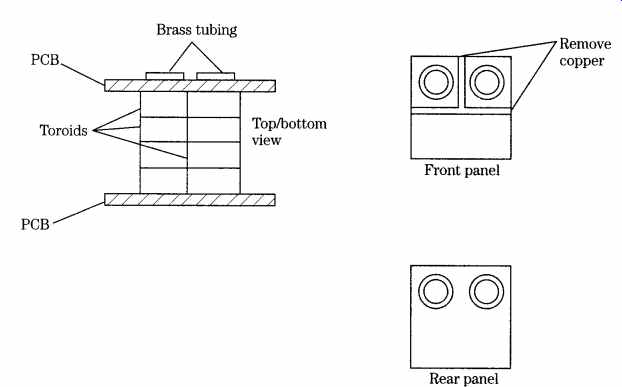
FIG. 21 Construction of the high-power Bazooka balun core with stacked toroid
cores and cop per (PCB material) end plates.
References
F. W. Grover, Inductance Calculation: Working Formulas and Tables, D. VanNostrand Co., Inc. (New York, 1946).
G. Bramslev, " Loop Aerial Reception," Wireless World, Nov. 1952, pp. 469-472.