AMAZON multi-meters discounts AMAZON oscilloscope discounts
NE-602 local oscillator circuits
There are two general methods for controlling the frequency of the LO in any oscillator circuit: inductor-capacitor (LC) resonant tank circuits or piezoelectric crystal resonators. Both forms are considered, but first, the crystal oscillators.
Fig. 17A shows the basic Colpitts crystal oscillator. It will operate with fundamental-mode crystals on frequencies up to about 20 MHz. The feedback net work consists of a capacitor voltage divider (C1/C2). The values of these capacitors are critical and should be approximately:
(eqn. 3)
(eqn. 4)
The values predicted by these equations are approximate, but work well under circumstances where external stray capacitance does not dominate the total. How ever, the practical truth is that capacitors come in standard values and these might not be exactly the values required by Eqs. (eqn. 3) and (eqn. 4).
When the capacitor values are correct, the oscillation will be consistent. If you pull the crystal out, then reinsert it, the oscillation will restart immediately. Alternatively, if the power is turned off and back on again, the oscillator will always restart.
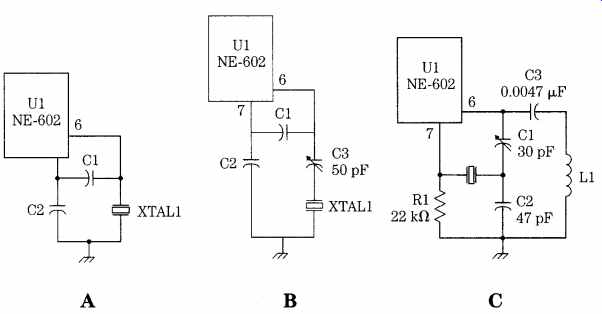
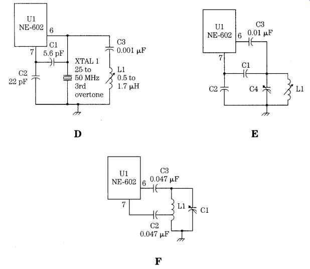
FIG. 17 Local oscillator circuits for the NE-602.
If the capacitor values are incorrect, the oscillator will either fail to run or will operate intermittently. Generally, an increase in the capacitances will suffice to make operation consistent.
A problem with the circuit of Fig. 17A is that the crystal frequency is not controllable. The actual operating frequency of any crystal depends, in part, on the circuit capacitance seen by the crystal. The calibrated frequency is typically valid when the load capacitance is 20 or 32 pF, but this can be specified to the crystal manufacturer at the time of ordering. In Fig. 17B, a variable capacitor is placed in series with the crystal to set the frequency. This trimmer capacitor can be adjusted to set the oscillation frequency to the desired frequency.
The two previous crystal oscillators operate in the fundamental mode of crystal oscillation. The resonant frequency in the fundamental mode is set by the dimensions of the slab of quartz used for the crystal; the thinner the slab, the higher the frequency. Fundamental-mode crystals work reliably up to about 20 MHz, but above 20 MHz, the slabs become too thin for safe operation. Above about 20 MHz, the thinness of the slabs of fundamental-mode crystal causes them to fracture easily. An alternative is to use overtone mode crystals. The overtone frequency of a crystal is not necessarily an exact harmonic of the fundamental mode but is close to it. The overtones tend to be close to odd-integer multiples of the fundamental (3rd, 5th, and 7th). Overtone crystals are marked with the appropriate overtone frequency rather than the fundamental.
Figures 17C and 17E are overtone-mode crystal-oscillator circuits. The circuit in Fig. 17C is the Butler oscillator. The overtone crystal is connected between the oscillator emitter of the NE-602 (pin 7) and a capacitive voltage divider that is connected between the oscillator base (pin 6) and ground. There is also an inductor in the circuit (L1); this inductor must resonate with C1 to the overtone frequency of crystal Y1. Fig. 17C can use either 3rd- or 5th-overtone crystals up to about 80 MHz. The circuit in Fig. 17D is a 3rd-overtone crystal oscillator that works from 25 to about 50 MHz and is simpler than Fig. 17C.
A pair of variable-frequency oscillator (VFO) circuits are shown in Figs. 17E and 17F. The circuit in Fig. 17E is the Colpitts oscillator version, and Fig. 17F is the Hartley oscillator version. In both oscillators, the resonating element is an inductor/capacitor (LC) tuned resonant circuit. In Fig. 17E, however, the feed back network is a tapped capacitor voltage divider; in Fig. 17F, it is a tap on the resonating inductor. In both cases, a dc-blocking capacitor to pin 6 is needed in order to prevent the oscillator from being dc-grounded through the resistance of the inductor.
Voltage-tuned NE-602 oscillator circuits
Fig. 18 shows a pair of VFO circuits in which the capacitor element of the tuned circuit is a voltage variable-capacitance diode, or varactor (D1 in Figs. 18A and 18B). These diodes exhibit a junction capacitance that is a function of the reverse-bias potential applied across the diode. Thus, the oscillating frequency of these circuits is a function of tuning voltage Vt. The version shown in Fig. 18A is the parallel-resonant Colpitts oscillator, and that in Fig. 18B is the series-tuned Clapp oscillator.
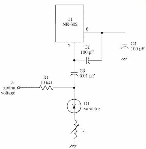
FIG. 18 Varactor-tuned oscillator.
The NE-602 is a well-behaved RF chip that will function in a variety of applications from receivers, to converters, to oscillators, to signal generators.
Receiver circuits you can build
One of the joys of experimenting with electronic circuits is building a project that not only works well but is useful and provides a certain amount of either enjoyment or utility later on. Radio receivers fall into that category but are generally considered advanced projects that cannot be accomplished by the average experimenter. Many people erroneously believe that only kit-built receivers are candidate projects for them because of the alleged complexity of radio receivers. However, modern integrated circuit electronics make it a lot easier to design and build your own receiver today than ever before. This section shows a few of the types of circuits that make up a radio receiver and offers some suggestions to custom tailor your own radio in the VLF, AM broadcast, or shortwave bands.
Direct-conversion receivers, popular with homebrewers (also see Section 6 for detailed information on direct-conversion receivers), also use a frequency-translation process, but it is entirely different in its nature from the superhet principle. The straight superhet will not demodulate CW and SSB signals unless a product detector is used in place of the envelope detector that "decodes" AM. But the direct-conversion receiver is basically a product detector that operates at the RF frequency to demodulate that signal directly to audio. The local oscillator in a direct-conversion receiver is tuned to the same frequency as the RF signal coming into the antenna. The difference frequency, when the LO is adjusted correctly, is the modulating audio frequency in the case of SSB and a selected side-tone frequency for CW (i.e., the frequency of the tone that you hear in the output).
The output of the superhet converter stage in a direct-conversion receiver is audio, but it might contain some residual elements of the RF and LO signals or other mixer products than the difference frequency. In order to smooth this output signal, therefore, a low-pass filter that passes only the audio signals is typically used down stream from the converter.
The direct-conversion receiver is not covered in detail here, but you can infer the design principles from the superhet paragraphs that follow. To cover the circuits that you can use to make your own home-designed receiver, let's start at the front end and work toward the detector and audio amplifier stages.
Front-end circuits
The front end of the radio receiver consists of the RF amplifier (if used) and the converter or mixer/LO stages. The basis for the designs are the Signetics NE-602 balanced-mixer integrated circuit. This device has limited dynamic range but is sufficient because it compensates with a better-than-average noise figure and sufficient conversion gain to make it possible to not use an RF amplifier in most projects.
The pinouts for the NE-602 IC converter are shown in Fig. 19. The two inputs together form a balanced pair, along with two outputs. In some cases, both outputs are used, but in others only a single output (pin 4) is used. Either an internal or external oscillator can be used with the NE-602, and both versions are presented here. In the selected circuits, the supply voltage for the NE-602 will be +5 Vdc to +9 Vdc.
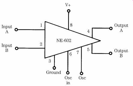
FIG. 19 Another view of the NE-602 integrated circuit.
Fig. 20 shows a simple superheterodyne converter circuit based on the NE 602 IC. The input circuit is broad-banded by using an RF transformer built on a toroid powdered-iron form. The turns ratio L2/L1 is typically 10:1 to 12:1; i.e., there are 10 to 12 turns on L2 for every turn on L1. Experiments and published data show good starting numbers are 20 to 24 turns on L2, with 2 to 3 turns in L1 for frequencies in the upper shortwave region. As the frequency is decreased, the number of turns is increased to about 34 to 40 turns on L2 at the AM broadcast band.
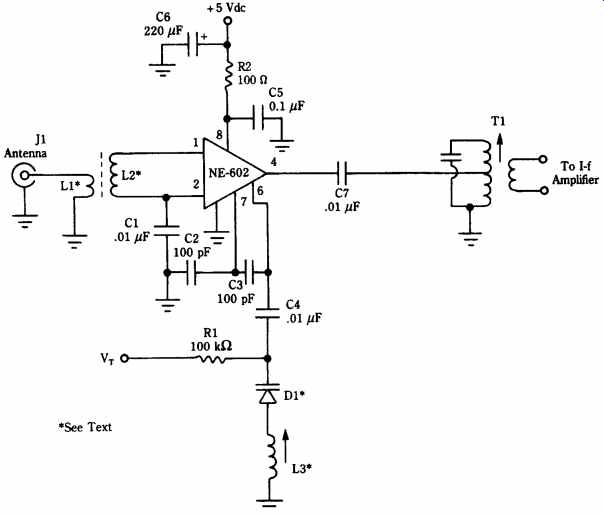
FIG. 20 NE-602 receiver circuit.
The capacitors and the 100-ohm resistor in the V+ circuit (connected to pin 8 of the NE-602) are used for isolation and decoupling. These components prevent RF in the NE-602 circuit from traveling to other stages in the radio via the dc power line or, alternatively, signals from other stages from modulating the converter stage (or possibly causing oscillations).
The oscillator circuit in Fig. 20 consists of the components attached to pins 6 and 7 of the NE-602 IC. The actual tuning is set by a variable-capacitance diode (varactor), D1. This diode is essentially a voltage-tuned capacitor. The oscillating frequency should be set 455 kHz above the desired RF frequency using Eq. (eqn. 1). If you know (or have on hand) either the capacitor or the inductor:
(eqn. 5) or (eqn. 6)
In all three expressions, the frequency is in hertz, inductance in henrys, and the capacitance in farads (don't forget to convert units from microhenrys, megahertz or kilohertz, and picofarads).
Example
Find the value of capacitance needed to resonate a 3.4-uH inductor to 9 MHz.
Note: 9 MHz = 9,000,000 Hz and 3.4 uH = 0.0000034 H.
Solution
91.9 pF
When making calculations, allow about 10 pF for stray-circuit capacitances. Also, the tuning circuit can consist of the diode plus a parallel capacitance. I've used a 22-pF varactor, 27-pF disk ceramic, and a 6- to 70-pF trimmer capacitor to tune HF receiver projects. Standard tuning diodes are available from replacement parts vendors, such as NTE. Part numbers of use in the HF region are the NTE-613 (22 pF) and NTE-614 (33 pF). For a wider tuning range, select the NTE-618 (440 pF).
The output of the NE-602 must be tuned to the IF frequency, i.e., the difference between the received RF signal and the local oscillator signal, by a tuned IF trans former (T1 in Fig. 20). For most receiver projects, this difference frequency should be 455-kHz because of the easy availability of the coils. Several sources offer these coils, but perhaps the easiest to obtain are the Bell/J. W. Miller (19070 Reyes Avenue, Rancho Dominguez, CA 90224) and the Toko coils marketed by Digi-Key (P.O. Box 677, Thief River Falls, MN 56701-0677; 1-800-344-4539).
IF amplifier circuits
The IF amplifier provides most of the gain in a superhet receiver, and it also sup plies the narrowest bandwidth in the signal chain. Thus, the IF amplifier is chiefly responsible for both the sensitivity and selectivity of the radio receiver. In fancy radio receivers, the IF amplifier can be quite complex, as witnessed by the designs used in modern shortwave and ham radio receivers in the kilobuck range. This one is a considerably simpler design, but is nonetheless effective. For those who need a more complex design, I recommend various editions of Bill Orr's The Radio Handbook or The ARRL Radio Amateur's Handbook.
Fig. 21 shows the basic circuit for an IF amplifier building block. For receivers requiring moderate gain, for example, an AM receiver intended primarily for local reception, then only one stage needs to be used. In shortwave receivers, or wherever superior sensitivity is sought, it is permissible to cascade two or three such stages to boost amplification. The gain of this stage is on the order of 50 dB, and some projects might need as much as 80 to 110 dB.
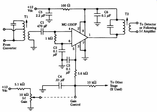
FIG. 21 Integrated circuit IF amplifier.
The basis for the IF amplifier building block is the MC-1350P gain block chip (this chip is also available as NTE replacement part number NTE-746).
The input circuit is tuned by either a single- or double-tuned transformer of the same sort used at the output of the NE-602 stage covered previously. The secondary impedance of this transformer should be on the order of 1000 ohm in order to properly match the input impedance of the MC-1350P. The output of the MC-1350P is also tuned by a similar IF transformer.
The gain in the MC-1350P device is controlled by the voltage applied to pin 5. This voltage must be varied between +3 and + 9 Vdc in order to set the overall gain of the stage. The gain-control voltage supplied to pin 5 can be derived from a manual gain control (i.e., potentiometer voltage divider), automatic gain control (AGC) circuit, or a combination of both.
Fig. 21 shows a sample manual gain control circuit based on a 10-kOhm potentiometer and a 5.1-kOhm fixed resistor. If a fixed gain is desired, then a fixed-ratio voltage-divider chain can be used instead. Also, it is not strictly necessary to use the same gain control for all stages in the combined IF amplifier. You can, for example, make one stage a variable-gain circuit and the other(s) fixed-gain.
Detector and audio circuits
Once the IF amplifier builds the signal up to a point where it can be successfully demodulated with good volume, you will want a detector circuit to recover the modulating audio. The simplest AM detector is the envelope detector shown in Fig. 22. The envelope detector is a single-diode rectifier at the output of the last IF transformer. The diode should be a germanium type, such as 1N34, 1N60, 1N270, ECG-109, or NTE-109 devices. A volume-control potentiometer serves as the load for the diode, and a 0.01-uF capacitor filters out a residual IF signal that remains in the circuit following demodulation.
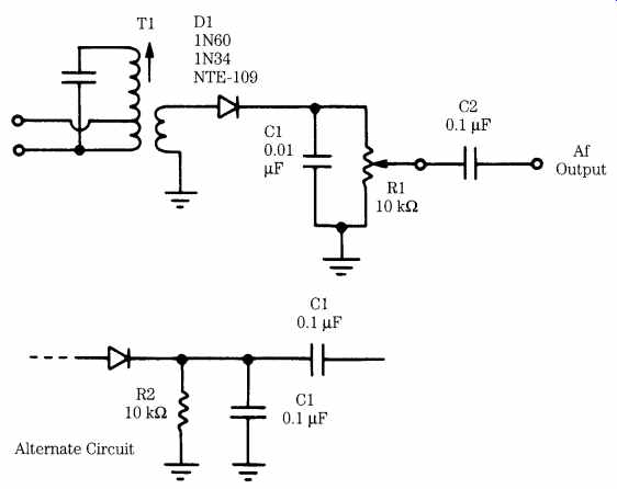
FIG. 22 AM envelope detector circuit.
The detector stage must be capacitor-coupled to protect the following stage be cause the demodulation process produces a small dc offset. The capacitor strips off the dc and makes the signal once again ac. In some cases, the audio stage following the detector contains the volume control, so an alternate circuit shown in Fig. 22 is used at the detector.
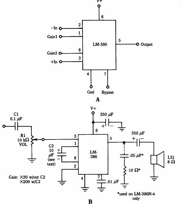
FIG. 23 (A) LM-386 audio amplifier integrated circuit; (B) LM-386 standard
circuit.
The basis for the audio stage is the easily obtained LM-386 IC audio subsystem chip (Fig. 23A). This chip is easily obtained in replacement semiconductor lines, from RadioShack and from a number of mail-order sources. Although the low power level leaves something to be desired, the LM-386 is both better behaved and more easily obtained than certain higher-powered audio subsystem chips.
Fig. 23B shows the basic circuit for the LM-386 chip when it is used as an audio stage for a receiver project. Notice that the circuit is extremely simple in that it basically has just input, output, ground, and V+ connections. The circuit is able to provide two levels of gain. If capacitor C2 is used, then the gain is 200; if the capacitor is deleted, the gain is 20. Normally, the gain will be set to 20 in receiver projects unless the design uses little gain ahead of the detector (which might be the case in the simplest superhets or in direct-conversion designs).
The LM-386 is relatively well-behaved in projects, which means that it takes only ordinary care in layout to achieve good results. It is possible, however, that because of the high gain, this IC will oscillate mercilessly if proper layout is not followed. Be sure to keep the inputs and outputs physically separated and don't allow the ground connections to wind all over the wiring board. Also, make sure that the V+ bypass capacitor is used . . . and has sufficient value (as shown).
Direct conversion
Fig. 24 shows the NE-602 chip used as a direct-conversion receiver. In this type of circuit, the local oscillator (LO) operates on the same frequency as the received RF signal. As a result, when the two are zero beat, the difference IF frequency is the audio modulating the incoming carrier. In CW reception, the LO is tuned to a frequency a few hundred hertz from the incoming RF. In that case, the difference frequency will be a beat note that is interpreted as a CW signal.
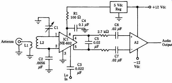
FIG. 24 Simple direct conversion receiver using the NE-602 "single IC
radio."
This section was not intended to design a radio receiver for you but rather to empower you to design your own radio receivers in the VLF, AM, and shortwave bands. The circuits are well-behaved and are easily built using readily available components.
Mechanical-filter IF amplifier
Selectivity is one of the "holy grails" of receiver designers and in many instances is more important than sensitivity or certain other specifications. The selectivity of the receiver is a measure of its ability to reject unwanted signals. The selectivity of a receiver is usually specified as the bandwidth between the points on the bandpass characteristic, where the gain falls off -6 dB (voltage) from the midband response.
Also important is the skirt factor, which is a measure of the shape of the IF bandpass curve. The skirt factor is the ratio of the bandwidth of the passband at -60 dB down to the bandwidth at -6 dB down from the midband response.
The IF amplifier provides most of the selectivity characteristic of the modern superhet receiver. But there is only so much that can be done with simple LC circuits.
If you want to achieve a very narrow selectivity characteristic, then it is necessary to use either a crystal filter or a mechanical filter. The mechanical filter provides the best tradeoff between selectivity and skirt factor. Unfortunately, new Collins mechanical filters cost a great deal of money. Surplus dealers, however, offer former military mechanical filters for a much lower cost. Fair Radio Sales of Lima, OH sells the filters from receivers, such as the R-390, R-392, and so on, at a reasonable price. These filters will have an IF frequency of 260, 455, or 500 kHz depending on the model.
There are also several bandwidths available: 500 Hz and 1.8, 2.9, 4, 8, and 16 kHz.
Fig. 25A shows the internal works of a typical mechanical filter, and Fig. 5 25B shows a comparison between mechanical filter bandwidth and typical LC-tuned circuit bandwidth. At each end are electromechanical transducers that consist of a bias magnet, coil, and drive(n) wire. These transducers act much like earphones or loudspeakers, but at IF rather than AF frequencies. The narrow bandpass is achieved with resonant metal disks coupled together with wire arms. These disks are cut to resonate at the center IF frequency.
The goal in constructing this project was to make a high-gain, 455- or 500-kHz IF amplifier with good selectivity characteristics to permit me to build a "super" AM radio receiver (to do some broadcast band DXing). This goal required an 8-kHz band width, 455-kHz mechanical filter. Fig. 26A shows the completed IF amplifier strip, and Figs. 5-26B (input side) and 5-26C (output side) show the actual internal circuit. The mechanical filter is the silver cylindrical object mounted to an L-bracket in Fig. 26B.
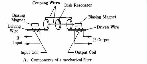
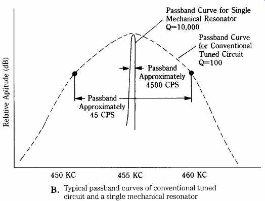
FIG. 25 Mechanical filter: (A) construction and (B) passband. U.S. Army
Signal Corp repair manual for R-390 receiver.
The input amplifier shown in Fig. 26B is shown as a circuit diagram in Fig. 26D.
The amplifier is a grounded-gate junction field effect transistor (JFET). The popular MPF-102 is used (same as NTE-312). Input signal is coupled through an altered 455-kHz IF transformer. The transformer is modified by crushing the resonating capacitor, which is accessible from the bottom outside of the shielded case of the transformer. The "secondary" of the transformer is used as the primary in this case. The drain terminal of the JFET is connected to V+ through a 1000-uH (1 mH) RF choke (RFC1) and a resistor-capacitor decoupling network. The output of the amplifier is coupled to the input of the mechanical filter (FL1) through a 0.1-uF dc blocking capacitor (C4). The 150-pF ceramic or mica trimmer capacitor (C5) across the input of FL1 is not necessary but is highly recommended. It will help adjust the flatness of the passband and peak the center frequency gain.
The output amplifier is shown in Fig. 26E. The gain is provided by a pair of MC-1350P gain-block IC devices. Interface to the output side of the mechanical filter is provided by another JFET (also an MPF-102), driven from a capacitive voltage divider (C6/C7).
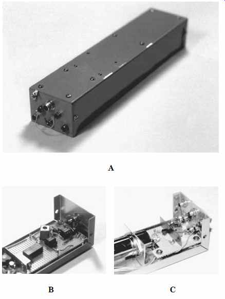
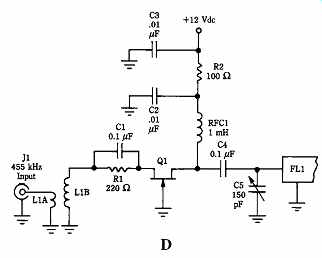
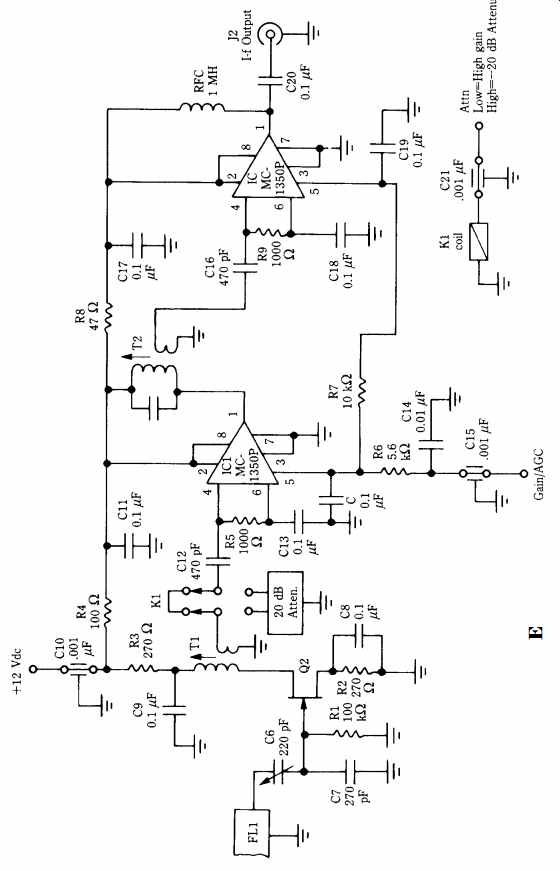
FIG. 26 IF amplifier project; (A) completed project: (B) input end; (C) output
end; (D) input amplifier stage; and (E) output amplifier circuit.
Signal from the drain of Q2 is passed to a relay circuit (K1) that selects either a shorted connection "straight through" or inserts a -20-dB attenuator in the signal path. This attenuator allows the receiver to operate with a high dynamic range in the presence of both large and weak signals (a necessity in an AM DX receiver!). You can either make a _-pad attenuator or use one of the ready-made varieties from Minicircuits Laboratories.
The attenuator relay (K1) is a +5-V "TTL compatible" type in a DIP package. It is operated by applying a +5-V signal to a feedthrough capacitor (C21) on the IF amplifier's metal case (Fig. 26A shows the several feedthrough capacitors used in this project). When the ATTN input is LOW (i.e., grounded, or 0.8 V), then the relay (K1) is inoperative and the signal is passed through the shorted terminals. But when the ATTN is high (i.e., 2.4 V< V< 5.2 V), then K1 is energized and inserts the -20-dB attenuator in the path.
The IF amplifier of Figs. 25 and 26 provides about 80 dB of gain at 455 kHz.
Shortwave receiver project
This section shows a simple radio receiver kit that will provide startlingly good performance for a very low cost. It is not the equal of a $1000 communications receiver, but it provides reasonably good performance in the HF shortwave band for only a few dollars. Perhaps most important is the fact that it serves as a good building block to add on other circuits.
Construction projects have long been part of the radio hobby; today, it is easier than ever before. A number of companies make small kits that are readily built in an evening or over a weekend. But few of these "one-nighters" are so grandiose as to be called receivers. However, Ramsey Electronics [793 Canning Parkway, Vic tor, NY, 14564; (716)-924-4560] makes several kits for hobbyists in addition to their line of frequency counters (I use a Ramsey 600-MHz counter on my work bench). The cost of the receiver with a black plastic cabinet is in the $40 region, less if all you want is the "innards" (supply your own cabinet). Contact the company for current prices.
This receiver is battery-operated and covers a selected segment of approximately 2.5 MHz somewhere in the range of 4 to 10.5 MHz. The tuning limitation is based on the range of the tuning capacitor diode and the overall limits on the slug tuned coil's inductance range. As it stands, the receiver will cover 40-m amateur band; the 8-MHz utilities, marine, and aviation band; and the 9-MHz international shortwave broadcast band.
The SR-1 shortwave receiver (Fig. 27) is based on the Signetics NE-602 RF converter chip. This chip provides the local oscillator and a double-balanced mixer in a single eight-pin mini-DIP package. In the case of the Ramsey SR-1, the input is untuned. Antenna signal is coupled to the broadband input transformer through a 5-kOhm "RF gain" control that actually functions as an attenuator [note: direct antenna circuit RF attenuation is an antique method that Ramsey resurrected].
The local oscillator circuit is inside the NE-602 chip but requires external tuning components. In the case of the SR-1, Ramsey elected to use a series-tuned variable frequency oscillator. The inductor in the LC tuning network consists of an IF trans former with the internal capacitor disconnected. Only one winding of the transformer is used, but you might suspect that the other winding would make a dandy alternative output for the oscillator in case you wished to drive a digital frequency-counter display.
The capacitor in the LC network is CR1, a varactor diode. That is, a voltage variable capacitance diode. The varactor produces a capacitance that is proportional to the applied voltage. A potentiometer from the +9-Vdc battery supply is used to provide the tuning voltage.
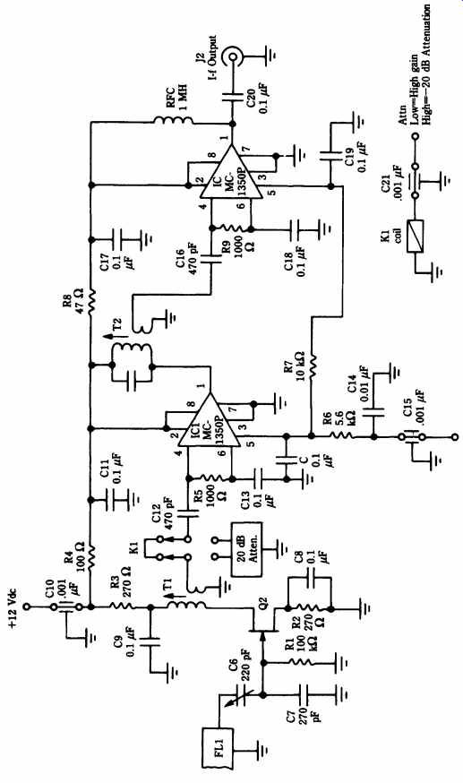
FIG. 27 Shortwave receiver project.
The NE-602 device is designed to operate from potentials in the +4.5- to +6-Vdc range, so the 1-kOhm resistor in series with the V+ terminal (pin 8) is absolutely required. The dc power supply is a 9-Vdc "transistor radio" battery mounted directly to the printed circuit board (Fig. 28). If you want to make this radio receiver into an ac-operated model, or a mobile model, then it might be necessary to build an external power supply. A type 7809 three-terminal voltage regulator IC will provide 9-Vdc regulated output from a +12-V (or higher) dc power supply.
The use of a voltage-regulated power supply, as described, will also help one problem with this design. The tuning is a function of applied voltage, so it will necessarily change when the battery voltage drops.
The receiver in Figs. 27 and 28 is a superheterodyne model, meaning that it converts the input RF frequency to a lower intermediate frequency (IF). The IF frequency is the difference between the RF frequency and the local oscillator (LO) frequency; that is: IF = RF - LO. In this project, the IF frequency is 260 kHz, so you can use components from Japanese AM car radios. However, there is a built-in limitation because of the 260-kHz IF frequency. The image frequency is too close to the RF frequency, so expect a terrible image response above about 10 MHz or so. Al though the chip will convert up to 200 MHz, the low IF frequency is not amenable to higher-frequency operation.
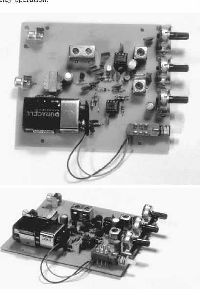
FIG. 28 Simple receiver project printed circuit.
In the model that I received, the audio output stage is a single 2N3904 transistor driving a set of earphones (not included). But the Ramsey people tell me that the de sign will soon be changed. The new circuit is the same as the old, except for re placement of the AF output amplifier with a high-gain LM-386 IC audio stage (Fig. 15B). This design provides higher gain and higher audio output power--a complaint that Ramsey tells me some builders made.
You can either build the receiver as is or use it as the basis for a project of your own. For example, you can replace the 260-kHz IF transformer and the tuning circuit components to make the circuit work at higher frequencies. You could also alter the tuning circuit to change the range. Adding some capacitance in parallel with the varactor will reduce the minimum frequency below 4 MHz. Winding new input and LO coils will also change the range. You can add a beat-frequency oscillator at the detector diode to make CW/SSB reception possible.
Alternatively, you can replace the IF tuning with a low-pass filter (that cuts off everything above about 3 kHz) and use this circuit as a direct-conversion receiver. In direct-conversion circuits, the LO operates on the RF frequency so the difference is the audio modulation. The direct-conversion technique works well on CW and SSB, but for AM it must be exactly zero-beat with the received carrier or a beat note will be heard.