AMAZON multi-meters discounts AMAZON oscilloscope discounts
The direct conversion, or synchrodyne, receiver was invented in the late 1920s, but only with the advent of modern semiconductor technology has it come into its own as a real possibility for good-performance receivers. Although most designs are intended for novices, and lack certain features of high-grade superheterodyne receivers, the modern direct-conversion receiver (DCR) is capable of very decent performance. A case can be made for the assertion that the modern DCR is capable of performing as good as many midgrade ham and SWL communications receivers. Although that assertion might seem very bold, experience bears it out. Although no one, least of all me, would represent the DCR as capable of the best possible performance, modern DCR designs are no longer in the hobbyist curiosity category. In this section, you will find the basic theory of operation and some of the actual designs tried on the workbench.
Basic theory of operation
The DCR is similar to the superheterodyne in underlying concept: The receiver radio frequency (RF) signal is translated in frequency by nonlinear mixing with a lo cal oscillator (LO) signal ("heterodyning"). Figure 6-1 shows the basic block diagram for the "front end" of both types of receiver. The mixer is a nonlinear element that combines the two signals, FRF and FLO. The output of the mixer contains a number of different frequencies that obey the relationship:

Fo _ mFRF _ nFLO,
( 1) where
Fo is the output frequency
FRF is the frequency of the received radio signal
FLO is the frequency produced by the local oscillator
All frequencies are in the same units m and n are integers (0, 1, 2, 3 . . .).
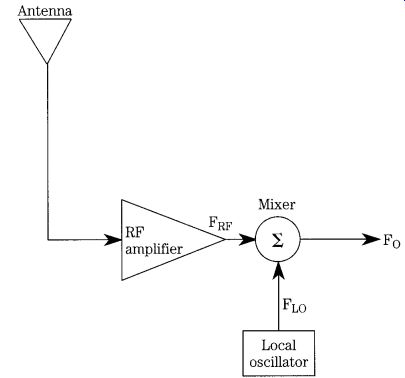
FIG. 1 Basic mixer-local oscillator circuit.
All frequencies other than FRF and FLO are product frequencies. In general, we are only interested in the cases where m and n are either 0 or 1, so the output frequency spectrum of interest is limited to FRF and FLO plus the product frequencies FRF _ FLO, and FRF _ FLO. The latter two are called sum and difference intermediate frequencies (IF). Other products are certainly present, but for these purposes, they are regarded as negligible. They are not regarded as negligible in serious receiver design, however.
In a superheterodyne radio receiver, a tuned bandpass filter will select either the sum IF or the difference IF, while rejecting the other IF, the LO and RF signals. Most of the gain (which helps determine sensitivity) and the selectivity of the receiver are accomplished at the IF frequency. In older receivers, it was almost universally true that the difference IF frequency was selected (455 and 460 kHz being very common), but in modern communications receivers, either or both might be selected.
For example, it is common to use a 9-MHz IF amplifier on high-frequency (HF) band shortwave receivers. On bands below 9 MHz, the sum IF is selected; on bands above 9 MHz, the difference IF is selected. A popular combination on amateur radio receivers uses a 9 MHz IF combined with a 5- to 5.5-MHz variable-frequency oscillator.
To receive the 75- to 80-m band (3.5 to 4.0 MHz), the sum IF is used. The same combination of LO and IF frequencies will also receive the 20-m (14.0 to 14.4 MHz) band if the difference IF (i.e., 14.0 _ 5 _ 9 MHz) is used.
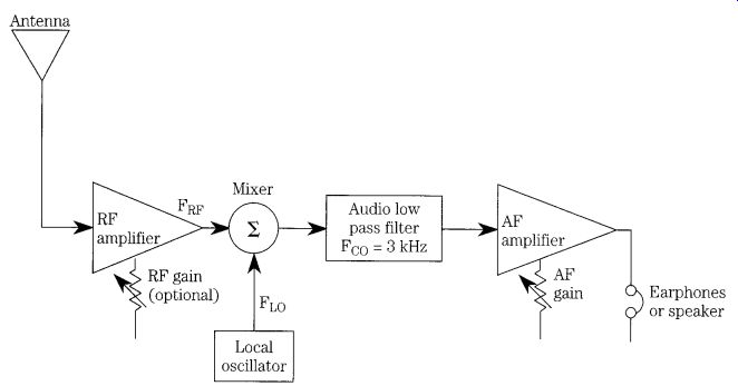
FIG. 2 Partial block diagram for a direct-conversion receiver.
In a DCR, on the other hand, only the difference IF frequency is used (see FIG. 2). Because the DCR LO operates at the same frequency as the RF carrier, or on a nearby frequency in the case of CW and SSB reception, the difference frequency represents the audio modulation of the radio signal. Amplitude-modulated (AM) signals are accommodated by zero-beating the LO to the radio signal, making FLO _ FRF(carrier). Thus, only the recovered upper and lower sidebands will pass through the system, and they are at the audio frequency.
For CW signals (Morse code on/off telegraphy) and single-sideband (SSB) signals, it is necessary to offset the LO frequency slightly to recover the signal. For the CW case, you must select a comfortable tone (which is an individual preference). In my own case, I am most comfortable using an 800-Hz (0.8 kHz) note when copying CW, so it will offset the LO from the RF by 800 Hz. For example, when copying a CW signal at, for example, 3650 kHz, the LO will be tuned to either 3649.2 or 3650.8 kHz.
In either case, the beat note heard in the output is 800 Hz. Single-sideband reception requires an offset on the order of 1.8 to 2.8 kHz for proper reception.
As was true in the superheterodyne receiver, the majority of the gain and selectivity in the DCR is provided by the stages after the first mixer. Although the super heterodyne uses the IF amplifier chain for this purpose, followed by second detection and audio amplification, the DCR must use only the audio amplifier chain.
Thus, it becomes necessary to provide some very high-gain audio amplifiers and audio bandpass filtering in the DCR design.
One implication of DCR operation is the lack of single-signal operation. Both CW and SSB signals will appear on both sides of the zero-beat point (FRF _ FLO exactly).
Although this feature can be a problem, it has at least one charming attribute on SSB reception: the DCR will receive LSB signals on one side of zero-beat and USB signals on the other side of zero-beat. There have been attempts to provide single-signal reception of SSB signals on DCRs by using audio and VFO phasing circuits (in the manner of the phasing method of SSB generation). That approach greatly increases the complexity of the receiver, which might make other design approaches more reasonable than DCRs. The most basic implementation of the DCR (FIG. 2) requires only a mixer stage, a local oscillator, and an audio amplifier. If the mixer has a high-enough output signal level, and high-impedance earphones are used to detect the audio, some de signs can make do without the audio amplifier. These are, however, a rarity, and the one version that I tried did not work very well.
In some DCR designs, there will be optional RF input signal conditioning consisting of a low-pass filter, high-pass filter, or bandpass filter (as appropriate) to select the desired signal or reject undesired signals. Without some frequency selection at the front end, the mixer is wide open with respect to frequency and may be un able to prevent some unwanted signal, or spurious combinations of signals, from entering the receiver circuits. Some designs will include more than one style of filter.
For example, a popular combination uses a single-staged tuned-resonant circuit at the input of the mixer to select the RF signal to be received and a high-pass filter with cut-off frequency FCO of 2200 kHz that is designed to exclude AM broadcast band signals. The reason for such an arrangement is that the AM signal might be quite intense, usually being of local origin, and is therefore capable of overriding the minor selectivity provided by the tuned circuit.
The RF amplifier used in the front end is also optional and is used to provide extra gain and possibly some selectivity. The gain is needed to overcome losses or inherent insensitivity in the mixer design. Not all mixers require the RF amplifier, so it is frequently deleted in published designs. In general, RF amplifiers are used only in DCRs operating above 14 MHz. Below 14 MHz, signals tend to be relatively strong and human-made noise tends to be much stronger than inherent mixer noise.
Problems associated with DCR designs
Over the years, there have been a number of articles in the popular technical press on DCR radio receiver designs, some of which are cited in this guide. In addition, the major amateur radio communications handbooks typically discuss DCR de signs. Several problems are cited as being common in the DCR receiver designs.
While these problems are very real, careful design and construction can render them harmless. The list of observed problems includes hum, microphonics, poor dynamic range, low output power levels (which makes for uncomfortable listening), and un wanted detection of AM broadcast band signals ("AM breakthrough").
Hum
Hum is caused by the alternating current (ac) power lines and may be radiated into the DCR through the antenna circuit, radiated into the wiring of the set, caused by ground loops, or communicated to the DCR circuits as ripple in the dc power sup ply. In the first two instances, the hum will have a frequency of 50 Hz ( Europe) or 60 Hz ( North America), which are the ac power-line frequencies; in the latter two cases, it will be 100 Hz ( Europe) or 120 Hz ( North America) if full-wave rectified dc power supplies are used. All hum problems are aggravated by the high-gain audio amplifiers used in DCRs; for this reason, bandpass filtering that attenuates signals below 300 Hz3 is highly recommended.
Hum signals received through the antenna circuits are best handled by use of high-pass RF filtering that does not admit energy in the 50/60 Hz region. The front end of many DCRs is wide open with respect to frequency, so improper choices can leave the receiver sensitive to hum. Some mixer circuits, such as the double balanced mixer (DBM) diode designs, are inherently insensitive to hum because of the nature of the inductors (and their cores) used in the associated inductors. If the hum is radiated into the circuit from the environment, then shielding the circuit against electrical fields will usually solve the problem.
Finally there is the case where hum is received via the dc power supply and is ripple-related (probably the most common cause). "Ripple" is the residual rectified ac (or "pulsating dc") riding on the output voltage of a dc power supply after all filtering and voltage regulation is done. The worst hum occurs when the dc power supply ripple modulates the LO signal. In that case, hum becomes worse as frequency increases.
4. A combination of good voltage regulation (which tends to limit ripple as if it were a very large filter capacitor) and proper grounding techniques will solve the problem.
Figure 3 shows one grounding sin that must be avoided at all costs. In the properly grounded receiver, all of the grounds will be connected to point "B" ("single-point" or "star grounded"). In actual practice, however, the nature of printed circuit or perforated wire board point-to-point wiring is such that the "star" ground concept is not achievable in its fullest sense, so there might be one or two additional points of grounding. Care must be taken to prevent ground loops in such cases.
The great sin in FIG. 3 is grounding the dc power supply to the antenna input ground point while the amplifier is grounded elsewhere. Even with very low resistance ground tracks, a considerable signal is created when the dc current required by the DCR flows from "A" to "B" and then into the receiver. For example, if the receiver draws 50 mA, and the track has a dc resistance of 0.05 ohm (neither number is unreasonable), a voltage drop of 2.5 mV will exist. Although this voltage seems small, it is not so small when followed by the 80 to 120 dB of gain typically found in a radio receiver. Under these conditions, even the smallest ripple waveform riding on the dc power-supply voltage can cause massive hum in the receiver's output! A solution to the hum problem is shown in FIG. 4. Single-point grounding is used in order to reduce ground loops. In addition, a toroidal decoupling choke is placed in the dc power supply leads.
5. This choke consists of two bifilar windings of 20 turns each over a toroidal core that has a permeability (_) between 600 and 1500.
The wire used to make the bifilar windings must be sufficiently large to accommodate the current requirements of the DCR circuitry.
3. 300 Hz is considered the low end _3 dB point for speech waveforms; the upper _3 dB point is usually specified as 3000 Hz.
4. Ibid. (ARRL Handbook).
5. ARRL Handbook (op. cit.).
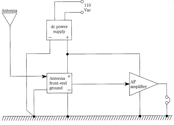
FIG. 3 Improper wiring of stages in direct-conversion receiver.
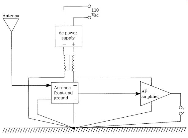
FIG. 4 Proper "star" wiring of direct-conversion receiver stages.
Of course, using batteries for the dc power supply will solve the problem of ripple-induced hum. Even so, good grounding technique is a fundamental requirement for building a good receiver.
Microphonics
Microphonics are a highly sensitive, damped, "echolike" ringing sound in the output when the receiver is vibrated or jarred and continues until the vibration dies out. It is caused by modulation of the signal by the vibration. Microphonics are generated because of the 80- to 120-dB gain associated with the typical DCR. Any modulation of the signal, therefore, produces change in the output signal. Two principal sources of microphonics are movement of the frequency-setting components (mostly the inductor) in the LO and changes in coupling between circuit elements (including wires). Ordinarily, the latter would not occur; DCRs usually have a tremendous amount of gain, so such possibilities exist.
Dynamic range problems
Dynamic range is basically the difference between the maximum and minimum signals that the receiver can accommodate and is usually expressed in decibels (dB).
A description of dynamic range found in Hayward and DeMaw describe it as:
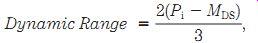
( 2) where
Pi is the signal level associated with the third-order intercept point of the receiver
MDS is the minimum discernible signal.
Dynamic range is important in all bands, but there are cases where it is most important. An example is when receiving any frequency when the receiver is in close proximity to an AM broadcast station, a currently transmitting ham operator, or other active transmitter site, regardless of the frequency being received. This problem becomes especially acute when the front-end of the receiver is wideband; there fore, it provides little or no discrimination against the unwanted frequencies.
However, also recognize that front-end tuning does not necessarily completely eliminate unwanted out-of-band signals that are very strong-especially if only one tuned circuit is provided.
6. Solid-State Design for the Radio Amateur, American Radio Relay League (Newington, CT, USA, 1977).
7. Ibid. (Campbell). Given the mixture of powerful international broadcasters and ham operators (both kilowatt and "QRP" stations), that claim is probably close to the mark.
Although normally associated with very large signals, another case where dynamic range improves signals is on very crowded bands, a large number of weak, moderate, and strong signals are mixed together. One source asserts that the dynamic range of signals received on a 40-m (7 to 7.3 MHz) half-wavelength dipole is greater than the dynamic range of an audio compact disk. 7 Intermodulation products and other spurious signals on these bands are often stronger than legitimate signals.
Although none of the myriad signals present would tax the receiver's capabilities by itself, the net result of all of them being simultaneously present is poor performance.
Being able to discriminate weak signals from strong signals, especially when using a wideband front end, is a benefit of having a high dynamic-range receiver. When the dynamic range of the receiver is insufficient for the task at hand, the output will be distorted and possibly very weak if desensitization occurs.
Several factors contribute to the dynamic range of the DCR, but the primary focus should be on the characteristics of the mixer circuit. Campbell provides three criteria for achieving a good dynamic range in the DCR.
8 Any RF device (such as a mixer) should be terminated in its output impedance for maximum signal transfer, minimum reflections, and proper operation. Indeed, many circuits will not perform as advertised, unless they are properly terminated.
Resistors in the signal path are to be avoided, especially prior to the high-gain audio section because resistors generate noise of their own. Even a "perfect" resistor will generate thermal noise (4KTBR), and practical resistors add some additional types of noise to the mix.
Restriction of the system bandpass prior to audio amplification is done because it reduces the unwanted noise components of the signal prior to processing in the high gain of the audio stages. The signal-to-noise ratio (SNR) is thereby improved.
This same trick is used by some authorities to justify using an "antenna-to-mixer" approach on expensive shortwave superheterodyne receivers. In those designs, the main bandpass filtering is at the output of the mixer, and the mixer input is driven directly from the bandpass filters in the front-end of the receiver (no RF amplifier).
This philosophy was used in the Squires-Sanders HF vacuum-tube receivers made in the United States some years ago. Although it was a novel approach at the time, it has become one of several possible standard approaches today.
Many designers of DCRs use a filter between the output of the mixer and the in put of the preamplifiers. If the filter is matched to the impedance of the mixer and the input of the preamplifier, and if it contains no resistors in series with the signal path, then it largely meets Campbell's criteria. The diplexer filter (of which, more later) largely meets these criteria.
8. Ibid. (Campbell): (1) proper termination of the mixer over a wide band; (2) avoidance of resistors in the signal path; and (3) restriction of the system bandpass prior to the audio preamplifier (which also helps hum rejection).
AM breakthrough
Stations in the AM broadcast band (540 to 1700 kHz), and in many regions of the world VLF broadcast band also, tend to be both relatively high-powered and very local to the receiver (thus very strong). As a result, many users of radio receivers for other bands are afflicted with the phenomena of AM breakthrough. This term refers to any of several phenomena, but the end result is AM interference to reception.
Sometimes the problem is caused by simple overload of the front end of the receiver, causing desensitization. In other cases, there will be intermodulation problems, and in still others severe distortion of the desired signals. In a great many cases the AM BCB signal will be demodulated and interfere with the audio from the desired station.
AM breakthrough is often accompanied by howling and screeching sounds from the receiver, although at other times, the effects are quite subtle. A frequently seen form of this problem is a strong background "din" caused by demodulation of the AM BCB signal in nonlinear elements in the circuit, particularly PN junctions.
9. The effects are usually more severe in simple DCR designs because the front end might be wideband.
Several different approaches are used to overcome AM breakthrough. First, the DCR should be well-shielded so that there is no "antenna effect" from circuit wiring.
Even so, coaxial cable should be used from the DCR printed circuit board to the antenna connector. In addition to shielding, which by itself does not affect signals riding in on the antenna, there should be at least some filtering of the input signal in a LC network. The network can be either a bandpass filter that passes an entire segment of the spectrum but restricts the rest or is tuned to a single frequency.
Another approach, which can be used in conjunction with either or both of these, is to place a high-pass filter that rejects the AM broadcast band in series with the signal path. Figure 6-5 shows two such filters that can be made with easily avail able components. Both of these filters are designed to be installed right at the antenna connector, either inside or outside of the receiver cabinet.
The AM rejection filter of FIG. 5A can be built with ordinary disk ceramic, silver mica, or Panasonic V-series mylar capacitors. Good performance is achievable with 5% tolerance units, although it is also a good practice to match them using a digital capacitance meter or bridge. If silver mica units are selected, then it is possible to select 1000-pF (0.001 _F) capacitors, using two in parallel for the 0.002-_F capacitors (C1 and C3). The inductors of this circuit are each 3.3 uH and can be either shielded inductors with regular cores or unshielded with toroidal cores. One combination that I've used is the Amidon Associates type T-50-2 (RED) toroidal core wound with 29 turns of no. 26 enameled wire.
The filter in FIG. 5B is a little more complex, but it offers as much as 40 dB of AM suppression in the HF bands. It is a high-pass filter with a cutoff near 2200 kHz.
Notice that the coils have different inductance values and are each in series with a capacitor. These coils are wound on Amidon T-37-2 toroidal forms.
Both of these filter circuits should be built inside of a well-shielded enclosure.
Most well-made aluminum sheet metal or die-cast project boxes will do nicely. How ever, be wary of the sort of sheet metal box that has no overlapping edges at the mating surfaces of the two halves of the box. A well-made sheet metal box will have at least 5 mm of overlapping flange built onto either the top or bottom half of the box.
These boxes are a bit more "RF tight" when joined together. Even so, additional screws might be necessary.
When laying out the filter on a perfboard or printed circuit board, be sure to use good construction practices. That is, lay out the components in a line from one end to the other, without excessive space between them and without doubling back so that the output is close to the input.
Low audio output
One of the frequent complaints about DCRs is that the audio level is too low for comfortable listening. The mixer output level is very low, so a DCR typically requires a large amount of gain in the audio amplifier chain to produce even minimal levels of power to earphones or loudspeakers. Additional gain and a reasonable power amplifier can be provided, but only at the risk of exacerbating all of those problems that come along with high gain in the first place. Attention to good layout, design, and grounding practices can greatly ease some of these problems without undue burden.
The use of proper filtering of the signal prior to the audio preamplifier will greatly enhance the enjoyment of listening to a DCR and reduce some of the problems associated with low power levels. The goal is to structure the bandpass of the receiver to that which is needed to pass the information content of the modulation but not the noise outside of that passband.
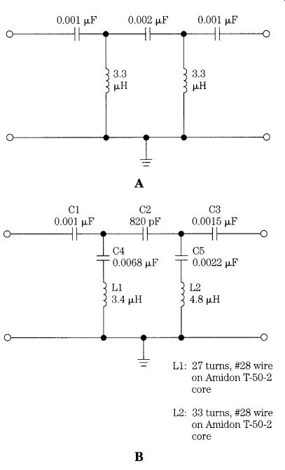
FIG. 5 Two filters for eliminating AM broadcast band interference.
Figure 6 shows the block diagram for a simple, but reasonable, DCR that is based on the principles developed in this section. Later in this section is a closer, more detailed, look at some specific circuits to fill the blocks, but for now the block diagram description will suffice. Notice that this description is functional, rather than stage-by-stage, so in most designs some of the blocks will be combined into a single stage.
The "front end" of the DCR of FIG. 6 consists of an AM-suppression high-pass filter, followed by either a tuned filter or bandpass filter at the frequency of choice.
An optional PIN diode attenuator circuit provides a degree of manual gain control for RF signals. The local oscillator is a variable-frequency oscillator (VFO) that tunes the entire band of interest. It must be relatively well designed and be free of drift and noise problems. The LO/VFO signal is mixed with the RF path signals from the chain of filters at the mixer circuit to produce a down converted signal that contains the modulation that you are attempting to recover.
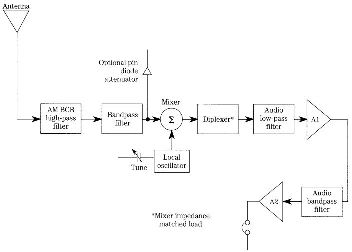
FIG. 6 Complete block diagram for a direct-conversion receiver.
The function following the mixer provides bandpass filtering to limit the effects of out-of-band signals, noise, and other artifacts while also providing the mixer with appropriate impedance termination at all frequencies (in practice, the mixer will be well terminated above and below the audio "base band" of interest, typically 300 to 3000 Hz, but is not well terminated in the base band). Amplifiers A1 and A2 provide the bulk of the necessary audio frequency gain, and a filter between them keeps the bandwidth correct for good noise suppression. In practice, amplifiers A1 and A2, and the audio bandpass filter, will be all part of one stage, although such is not a requirement. Hayward and others advocate the use of a postfilter at the output of the high gain stages. This filter should have a bandwidth matched to the system bandwidth, although one source recommends "slightly wider" without being too specific. The purpose of the postfilter is to reduce the noise generated in the high-gain audio amplifiers (which can be considerable). Following the high-gain stages is an audio power amplifier that boosts the signal sufficiently for either headphones or a loud speaker. An audio volume control will be provided at this point, or perhaps earlier in the chain.
Mixer circuits in direct-conversion receivers
The principal element in any direct-conversion receiver (DCR) is the mixer. The mixer is a nonlinear circuit element that exhibits changes of impedance of cyclical excursions of the input signals. When mixing is linear, one signal will ride on the other (see FIG. 7A) as an algebraic sum (i.e., the two waveforms are additive), but the product (i.e., multiplicative) frequencies are not generated. In nonlinear mixing, the classic amplitude-modulated waveform (FIG. 7B) is produced when the two frequencies are widely separated. A mixer that produces product frequencies can be used either in DCRs or superheterodyne receivers. In superhet terminology, it is common to call the frequency translation mixer that produces the IF signal a first detector and the mixer that recovers the audio modulation either a product detector or a second detector, even though exactly the same sort of circuit can be used by either case.
Any number of mixer circuits are used in radio receivers, and most of them are candidates for use in direct-conversion receivers. In nearly all cases, the output circuit of the mixer will be a low-pass filter that passes audio frequencies but not RF frequencies.
Two issues dominate mixer selection for DCR service: sensitivity and dynamic range. The former determines how small a signal can be detected, and the latter determines the ratio between the minimum detectable signal and the maximum allow able signal. Some passive mixers produce so much loss, so much noise, and require so much signal strength to operate that they are simply not suited to DCR design (unless adequate preamplification is provided). Such detectors can sometimes be put to good use in superheterodyne receivers because they are preceded by the gain of the front end and the IF amplifier chains, which can be considerable.
There are two issues to resolve when selecting a mixer element for a DCR. First, there is always the possibility of radiation of the local oscillator (LO) signal back through the antenna. In order to prevent this problem, it is necessary to keep the mixer unilateralized (i.e., the signal flowing in only one direction through the circuit). Some mixers are inherently good in this respect, and others are a bit problematical. In cases where LO radiation might occur an RF amplifier should be used ahead of the mixer, regardless of whether it is needed for purposes of improving sensitivity or selectivity.
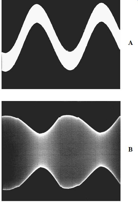
FIG. 7 (A) Linearly mixed signals and (B) nonlinearly mixed signals result
in the AM modulation waveform when two frequencies are wide apart.
The second problem that must be resolved is transmission of the RF and LO signals to the output of the mixer. You normally only want the first-order sum and difference frequencies. Many forms of the simple mixer circuit are particularly bad in this respect, and others are considerably better. Theoretically, any mixer can be used for the front end of the DCR; however, the simple half-wave rectifier diode envelope detectors are not at all recommended. Representative mixer circuits are covered in Section 10.
Considerations for good DCR designs
It probably does not surprise many readers that there are some principles of good design that result in superior DCR performance.
Even relatively simple DCR designs, including those based on the Signetics NE-602 integrated circuit double-balanced modulator [12] and the popular LM-386 audio amplifier, have proven to be very sensitive and free of hum and microphonics, even though that combination is not without critics. Dillon's design, which was tested in the laboratories of the American Radio Relay League (ARRL), proved remarkably free of the problems often associated with simple DCR designs.
[13]
One method for terminating the mixer is to place a resistor-capacitor (RC) net work across the "IF OUT" terminals of the mixer and ground (see FIG. 8). The SBL-1 mixer is designed for 50-_ input and output impedances, so the device is terminated in its characteristic impedance at RF frequencies by the 51-_ resistor (R1). Be cause capacitor C1 has a value that produces a high reactance at audio frequencies (AF) and a low reactance at RF, the mixer is terminated for any residual LO and RF signal (which are absorbed by R1), but AF is transmitted to the low-pass filter.
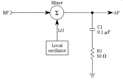
FIG. 8 Mixer termination for high frequencies (above audio).
Some practical design approaches
The literature on DCRs has several different popular approaches, and each has its own place. Some of the simpler designs are based on the combination of a Signetics NE-602 device and a LM-386 IC audio section. Others are based on different IC devices, such as the Signetics TDA7000 or some other product. These chips were designed for the cellular telephone and "cordless" telephone markets as receiver front ends. Still others are based on commercial or homebrew double-balanced modulators. This section examines several of these approaches.
The NE-602 type of DCR is relatively easy to build and provides reasonable performance for only a little effort. The NE-602 chip is relatively easy to obtain; for the most part, it is well-behaved in circuits (i.e., it does what it is supposed to do). It has about 20 dB of conversion gain, so it can help overcome some circuit losses, and it reduces slightly the amount of gain required of the audio amplifier that follows. The NE 602 can provide very good sensitivity; on the order of 0.3 _V is relatively easy to obtain, but it lacks something in dynamic range. Although the specifications of the de vice allow it to accept signals up to _15 dBm, at least one source recommended a maximum signal level of _25 dBm.
At higher input signal levels, the NE-602 tends to fall apart.
The newer NE-612 is basically the same chip but has improved dynamic range.
Figure 9 shows the basic circuit of the simplest form of NE-602 DCR. The input and LO circuits can be any of several configurations, although the one shown here is probably the most common.
The output signal is taken from either pin 4 or pin 5 and is fed to an audio amplifier. This circuit configuration will work, but it is not recommended. There will be a fairly large noise and image signal component and no filtering.
The Dillon design shown in FIG. 10 uses the push-pull outputs of the NE-602 (i.e., both pins 4 and 5) and is superior to the single-ended variety. According to Dillon, the balanced output approach improves the performance, especially in regard to AM BCB breakthrough rejection. Also helping the breakthrough problem is the use of a 0.047-uF capacitor across the output terminals of the NE-602.
Daulton takes exception to the use of the NE-602 as the DCR front end and prefers instead to use the Signetics TDA-7000 chip. Although functionally similar to the NE-602, the TDA-7000 is more complex and is said to deliver superior performance with respect to dynamic range and signal-overload characteristics. Figure 6-11 shows a DCR front-end circuit that is based on the TDA-7000 after Daulton's design.
This circuit uses the same balanced front end as other designs and, like the typical NE-602 design, uses the internal oscillator for the variable-frequency oscillator (VFO). The circuit following this front end should be of the sort typically found in the NE-602 designs. This particular variant uses the internal operational amplifiers of the TDA-7000 to provide active bandpass filtering.
A simplified variant on the Lawellen design18 is shown in FIG. 12 (the original design included a QRP transmitter as well as the DCR). The front end of this variant consists of an RF transformer with a tuned secondary winding (L1A). This secondary is tuned to resonance by capacitor C1 and is tapped at the 50-_ point in order to match the input impedance of the double-balanced mixer (DBM).
The particular DBM selected here is a Mini-Circuits SBL-1-1, although in the original article, Lawellen used a homebrew DBM made from diodes and toroidal transformers. The RF signal is input to pin 1 of the DBM (which can accommodate signal levels up to _1 dBm), and the local oscillator signal ("VFO IN") is applied to pin 8 through capacitor C2. The VFO/LO signal must be on the order of _7 dBm.
The design of FIG. 12 uses two methods for matching the output of the mixer circuit. First, there is an RC network (R1/C3) that matches high frequencies to 51 _ (the capacitor limits operation to high frequencies). The second method used here is to use a grounded-base input amplifier (Q1) to the audio chain. Such an amplifier applies input signal across the emitter-base path and takes output signal from the collector-base path (the base being grounded for audio ac signals through capacitor C5). This preamplifier is equipped with an active decoupler circuit, consisting of transistor Q2 and its associated circuitry. The input side of the grounded base audio amplifier consists of a LC low-pass filter (C4/RFC1) that passes audio frequencies, but not the residual VFO and RF signals from the DBM. In the original design, Lawellen followed the grounded-base amplifier with a direct-coupled operational amplifier active low-pass filter.
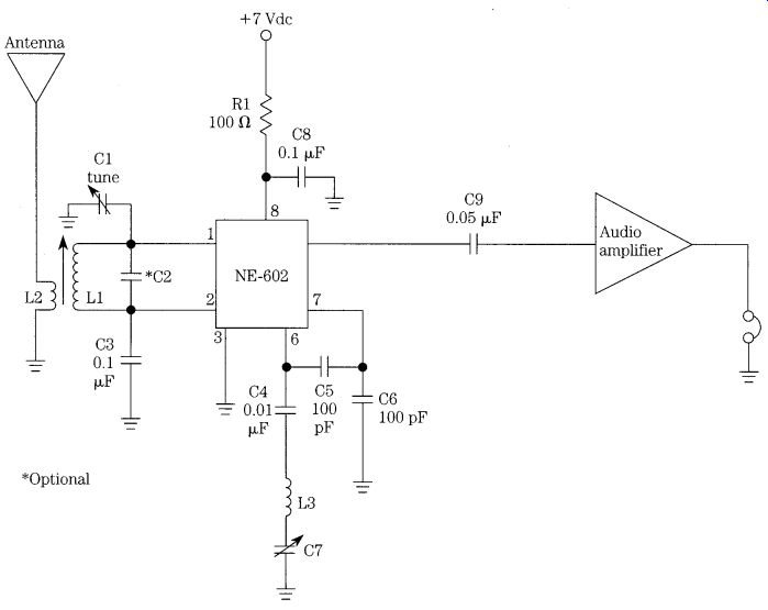
FIG. 9 Partial schematic of NE-602 direct conversion receiver.
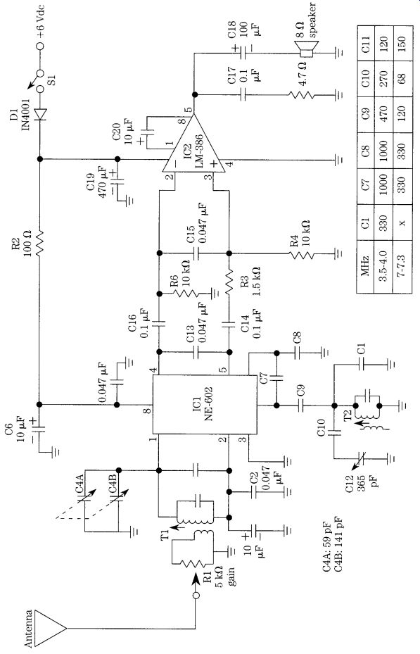
FIG. 10 Complete schematic of direct-conversion receiver using NE-602.
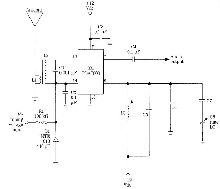
FIG. 11 Direct-conversion receiver using TDA-7000 chip.
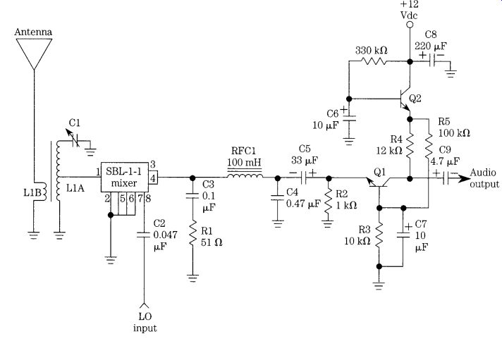
FIG. 12 Direct-conversion mixer and first audio using the SBL-1-1 DBM.
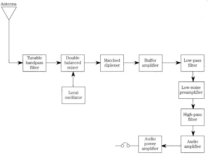
FIG. 13 Block diagram for a complex direct-conversion receiver.
The Campbell design extends the concepts from Lawellen. Figure 13 shows the block diagram for a portion of Campbell's direct conversion receiver. The front end consists of a double-balanced mixer followed by a matched diplexer filter that provides a 50-ohm input impedance from dc to 300 Hz and from 3000 Hz to some up per high-frequency beyond the range of interest. The diplexer also passes the standard communications audio bandwidth (300 to 3000 Hz) to the matched grounded base amplifier. Finally, there is an LC audio bandpass filter prior to sending the signal on to the high-gain audio amplifier stages.
Figure 14A shows the passive diplexer used by Campbell. It consists of several inductor, resistor, and capacitor elements that form both low-pass and high-pass filter sections. The values of the inductors (L1, L2, and L3) are selected with their dc resistance in mind, so it is important to use the originally specified components or their exact equivalents in replicating the project. Campbell used Toko Type 10RB inductors: L1 is Toko 181LY-392J, L2 is Toko 181LY-273J, and L3 is Toko 181LY-273J.
These coils are available from Digi-Key ( P.O. Box 677, Thief River Falls, MN 56701- 0677, USA; Voice 1-800-344-4539; FAX 218-681-3380).
Campbell's article supplied me with another example of the "digital myth," i.e., the concept that the digital implementation of a function is always superior to the analog version. He points out that the dynamic range of an LC filter is set by the inductors. The low-end is the thermal noise currents created by the circuit resistance (4KTBR), and the upper end is set by the saturation current of the inductor cores.
For the parts selected by Campbell, he claims this range to be 180 dB. By contrast, an expensive 24-bit audio A/D converter provides only 144 dB of dynamic range.
The matched 50-ohm audio preamplifier is shown in FIG. 14B and is an improved version of the Lawellen circuit. According to Campbell, this circuit provides about 40 dB of gain and offers a noise figure of about 5 dB. The range of input signals that it will accommodate ranges from about 10 nV to 10 mV without undue distortion.
These specifications make the amplifier a good match to the DBM. Like the Lawellen circuit, the Campbell circuit uses a grounded-base input amplifier (Q1) and an active decoupler (Q2). But Campbell also adds an emitter-follower/buffer amplifier (Q3).
A set of three passive audio filters, which can be switched into or out of the circuit, is shown in FIG. 14C. These filters are designed for termination in an impedance of 500 ohm. Three different bandpasses are offered: 1, 3, and 4 kHz. The 4-kHz filter is a fifth-order Butterworth design, while the 3-kHz filter is a seventh-order Elliptical design after Niewiadomski. 20 The 1000-Hz design is scaled from the 3000-Hz design. Campbell claims that these filters offered a shape factor of 2.1:1, with an essentially flat passband ". . . with rounded corners, no ripple and no ringing." Campbell implied the use of switching, as shown in FIG. 14C, but did not actually show the circuitry. As shown here, the switching involves use of a pair of ganged SP3P rotary switches. PIN diode switches can be used for this purpose.
A complex DCR was designed by Breed and reported in the amateur radio literature as a direct-conversion single-sideband receiver. 21 The single-sideband (SSB) mode is properly called single-sideband suppressed-carrier amplitude modulation, for it is a variant of AM that reduces the RF carrier and one of the two AM side bands to negligible levels. This mode is used in HF transmissions because it reduces the bandwidth required by half and removes the carrier that produces heterodyne squeals on the shortwave bands.
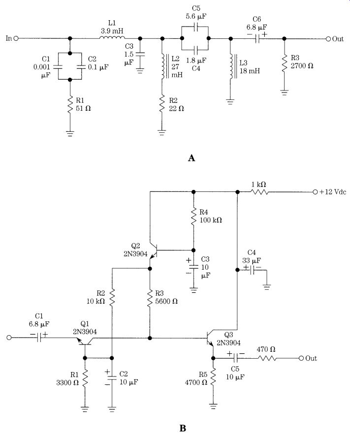
FIG. 14 (A) Diplexer circuit for DBM; (B) audio postamplifier; and (C) three
audio bandpass filters.
There are two methods for generating SSB. The most common today uses a double-balanced modulator to combine a fixed carrier and the audio signal to pro duce a double-sideband suppressed-carrier output signal; the unneeded sideband is then removed by filtering. The older and more-complex variant uses a phasing method of SSB generation. Breed uses the inverse process to demodulate SSB signals in a clever, but complex, receiver design (FIG. 15). This circuit splits the in coming RF signal into two components, then feeds them both to separate mixers.
These mixers are driven 90 degrees out of phase by a VFO that produces _45_ and _45_ outputs. The respective outputs of the mixers are amplified, then fed to bilateral 90_ audio phase-shift networks, where they are recombined. The output of the phase-shift network is filtered in a low-pass filter and bandpass filter to provide the recovered modulation.
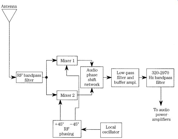
FIG. 15 Phased CW/SSB direct-conversion receiver.
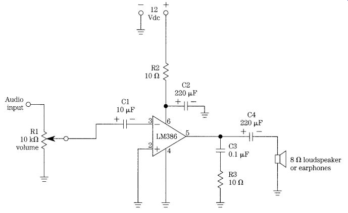
FIG. 16 LM-386 audio power amplifier stage.
Audio circuits
The audio chain in the direct-conversion receiver tends to be very high gain in order to compensate for the low output levels usually found on the mixer circuits.
The principal job of the audio amplifier is to increase the signal level by an amount that will create comfortable listening level while also tailoring the bandpass characteristics of the overall receiver to limit noise and other artifacts. Although any number of discrete and integrated circuit (IC) circuits are suitable, most designers today tend to use the IC versions that uses a discrete circuit with IC preamplifiers. Most other designers today use all-IC circuits. Figure 12-16 shows a simple LM-386 design while the published literature shows many other designs as well.
The LM-386 design of FIG. 16 is the single-ended configuration for the LM-386 low-power audio stage. This IC device contains both preamplifiers and power amplifiers for a nominal output power of 250 mW. 23 The LM-386 series of audio power ICs are easy to use, but because of the high gain needed, it will oscillate if layout is not correct or if grounding is not proper. There are two basic circuit configurations for the LM-386. The differential version was shown in FIG. 10 (Dillon's design); FIG. 16 shows the more common single-ended design. The gain of the circuit can be either 46 dB (_200) when capacitor C2 is used or 26 dB (_20) when C2 is deleted (leave pins 1 and 8 open-circuited).
Local oscillator circuits for direct-conversion receivers
The local oscillator (LO) for a continuously tunable receiver of any description is basically a variable-frequency oscillator (VFO). Although higher-grade receivers today typically use frequency-synthesis techniques for generating the LO signal, the standard inductor-capacitor (LC) controlled VFO still has appeal for less-complex receivers. The VFO used for the LO in receivers is pretty much the same as the VFO in transmitters, so transmitter VFOs are frequently used. In some cases, however, a receiver LO has at least one specification that is more rigid than the transmitter equivalent: many receivers have a requirement for low FM phase noise. In the main, however, amateur radio applications of direct-conversion receivers typically use the transmitter VFO for the receiver as well.
Several different VFO designs are used for receiver LOs: Armstrong, Hartley, Colpitts/Clapp, and an amplitude-limiting design. The first three of these circuits are recognized according to the nature of their respective feedback networks, and the other is recognized by the special connection of a transformer. Notice that the Colpitts and Clapp are basically the same circuit, except that the Colpitts uses a parallel-tuned LC frequency-setting network and a Clapp oscillator uses a series-tuned LC network.
A common test chassis for projects
Part of the decision to build and test several direct-conversion receivers involved having a common chassis for all three designs. Although not very elegant, being made of scrap aluminum chassis and bottom plates from the "junk box," it was at least low cost and effective. Figure 6-17 shows the receiver test bed front panel. It is fitted with a Jackson Brothers calibrated dial with a 10:1 fast/slow vernier drive. The 6.35-mm (0.25 in) shaft coupling on the vernier drive is used to turn either a variable air-dielectric capacitor or potentiometer, depending on whether the DCR being built is a mechanically tuned or a voltage-tuned version. For most of the experiments, the voltage-tuned variety was used. Two additional controls are also provided, and both are potentiometers. The pot to the right of the tuning knob is a volume control, and that to the left is the RF tuning control (for voltage-tuned frontend circuits).
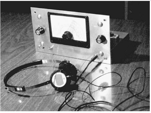
FIG. 17 Photo of direct-conversion receiver.
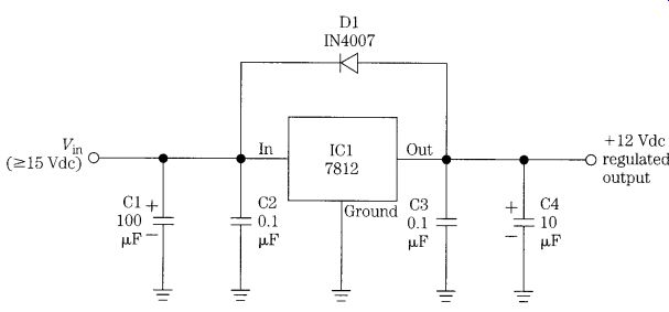
FIG. 18 Dc power-supply circuit.
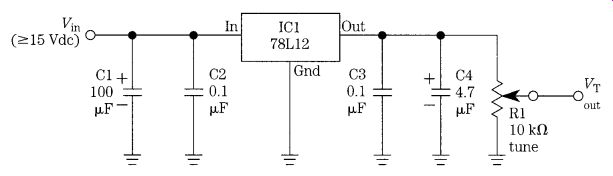
FIG. 19 Voltage tuning power supply.
Three circuits are provided for the test bed: two dc power supplies and an LM-386 audio power amplifier. One dc power supply (FIG. 18) is used to provide _12 Vdc (regulated) to the circuits of the DCRs used on the test bed. It uses a 7812 three terminal IC voltage regulator and works from a _15-Vdc (or higher) source. In this project, raw power was provided by a series of three 6-V lantern dry-cell batteries connected in series. The second dc power supply (FIG. 19) consists of a 78L12 low power, three-terminal voltage regulator and a potentiometer. The potentiometer is for main tuning and is ganged to the main dial of the chassis. In normal use, this potentiometer is used to tune the local oscillator (LO) of the DCR.
The audio amplifier is the LM-386 low-power "audio system on a chip" device.
The LM-386 uses a minimum of external components and includes both the audio preamplifiers and the power amplifiers to produce between 250 mW and 700 mW of audio power, depending on the particular device specified. The circuit for the audio section is shown in FIG. 20, and its location on the test bed chassis is shown in Fig. FIG. 21. Notice that the audio section has its own _12-V regulator. This is an optional feature, but it does keep load variations in the audio amplifier from coupling to the rest of the circuitry. The audio section is the small circuit board on the left side of the chassis, right by the audio volume control.
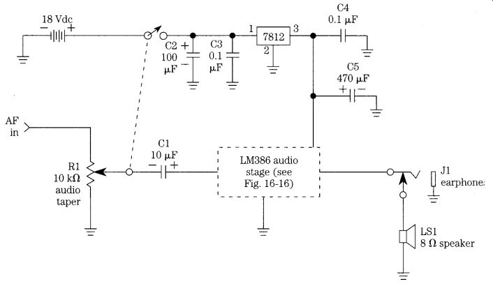
FIG. 20 Dc power supply for LM-386 power amplifier.
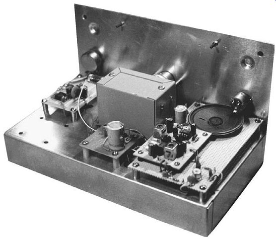
FIG. 21 Rear view of the DCR test bed chassis.
Figure 21 shows the rear view of the DCR test bed chassis. As mentioned, the audio amplifier section is shown on the left. The gray metal box contains either the variable air-dielectric capacitor or the potentiometer and power supply (FIG. 19), either of which can be used to tune the local oscillator of the DCRs being tested.
The _12-Vdc power supply is located on the small printed circuit board to the rear of the tuning box. Space is provided to the right of the tuning box for the circuitry of the DCR being tested. This board is changed from one project to the other.
Wiring board construction used two different methods. The audio amplifier, the tuning dc power supply, and +12-Vdc regulated power supply were built on Radio Shack "universal" printed circuit boards. The DCRs, on the other hand, were wired using Vector perfboard with a hole grid on 0.100 centers or an equivalent product.
Three different antennas were used for testing the DCRs in this section: a 5BTV Cushcraft 0.5-wavelength ham band vertical, an outdoor 30-m (100-ft) random-length end-fed wire, and a 6-m (20-ft) wire strung across the ceiling of my basement workshop. Interestingly enough, on the HF bands, there was not a large difference between the two outdoor antennas' performance and only slightly more difference between the outdoor antennas and the indoor antenna. On the VLF band, however, the random-length wire was clearly superior to the other two antennas.