AMAZON multi-meters discounts AMAZON oscilloscope discounts
The principle of tape-recording is straightforward enough, and work on simple magnetic recorders was going on as early as 1900. In the first systems a steel wire was used as the recording medium, but today magnetic tape is universal.
The tape is pulled past a head at a constant speed by the drive mechanism. The head consists of a core, made from a magnetic but non-conducting material such as ferrite, or sometimes laminated iron. The core is made as a closed circle, with an extremely narrow gap where the core touches the tape. A coil of insulated wire is wound on the core, shown diagrammatic ally in Fig. 1.
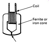
FIG. 1 a tape record/playback head ---- Gap- filled with a non-magnetic
material.
The tape itself consists of a flexible (but non-stretch) plastic base, coated on one side with a magnetic powder. Ferrite (an oxide of iron) is commonly used, but other materials such as chromium dioxide are now used as well. The particle size is extremely small.
If an alternating current is passed through the coil in the head, a magnetic field will be induced in the gap in the core, and the field will vary in proportion to the current flowing. If the tape is moving past the head at the time, the varying magnetic field will cause a pattern corresponding to the alternating current to be recorded on the tape in the form of changes in patterns of permanent magnetism. Fig. 2 illustrates this. The alternating current applied to the head can be obtained from the output of an amplifier, and the input to the amplifier can be via a microphone.
This will permit recording speech on the tape, in the form of magnetic patterns.

FIG. 2 during recording, the head produces patterns of magnetization
on the magnetic tape
Pattern of magnetism
To replay the tape, the head is connected to the amplifier input. As the tape is pulled over the head, the permanent magnetic patterns previously recorded on it will induce a voltage in the coil that is closely similar to the speech pattern. The amplifier's output is connected to a speaker, and the system will replay the original speech-more or less. A simple system diagram for a tape-recorder is given in Fig. 3. The switch is shown in the 'playback' position (marked P) and the head feeds the amplifier, which drives the speaker. In the 'record' position (marked R) a socket-for a microphone-is connected to the amplifier input, and the output is fed to the head. Although a moderately large signal, typically a few volts, is needed to record a signal on the tape, the output from the head during playback is small. One channel of a stereo cassette recorder head will give at most a few hundred microvolts of signal.
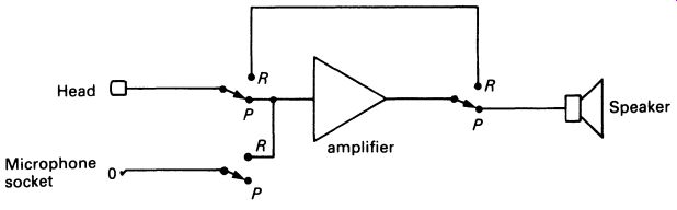
FIG. 3 system diagram for a simple tape-recorder.
The tape can be erased by applying a powerful magnetic field to saturate it and destroy the previous recording. In low-cost portable recorders a small permanent magnet is used for this purpose, swung into contact with the tape when the 'record' button is pressed. Erasing a tape in this way leaves a residual noise (hiss) on the tape, so in higher-quality recorders the tape is erased with a powerful high frequency alternating magnetic field, applied with a special erase head. The erase head is similar to a record/ playback head, but has a wider gap and, usually, a larger coil-the object is to deliver a high power field to the tape, not to record a signal. Tapes erased by demagnetizing them are quieter, with less background noise, than tapes erased with a magnet.
Unfortunately a tape-recorder based on such a simple circuit as the one shown in Fig. 3 sounds dreadful. Replay is satisfactory, but substantial distortion is introduced during recording. The problem is caused by a basic physical fact, that induced magnetism is not linear. If there is a very small signal to be recorded, a small degree of permanent magnetism is left in the tape-this is called the remanent magnetism. Doubling the field will not double the remanent magnetism; at low levels and at high levels the remanent magnetism changes more slowly than the inducing field. Fig. 4 shows a graph comparing the shape of the 'curve' for a steadily increasing field strength with the curve for the remanent magnetism which would result. The middle of the right-hand curve is flat, but distortion will occur if the signal is recorded near the top or bottom of the characteristic.
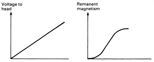
FIG. 4 the remanent magnetism in the tape does not bear a linear
relationship to the magnetizing force

FIG. 5 distortion of a recorded sinewave resulting from the non-linear
magnetization characteristic
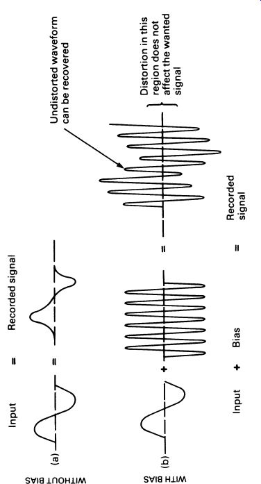

FIG. 6 comparing recording systems with and without bias; the addition
of ultrasonic bias provides a means of recording an undistorted audio
waveform on magnetic tape.
When an audio signal, which is alternating, is fed to the record head, the direction of magnetism reverses every time the waveform crosses the zero line. Fig. 5 shows what happens when a simple sinewave is used.
This means that the sinewave will be distorted, as shown in the diagram, every time it approaches the zero line. Avoiding the distortion at the 'high' end of the characteristic is easy-it is merely necessary to ensure that the signal is not too loud. But the problem near zero is harder to cure. The method is in fact to mix the audio signal with a constant high frequency note, a sinewave at 40kHz or more, well beyond the audible range. This technique, known as ultrasonic bias (or sometimes, less correctly, 'super sonic bias'), ensures that the audio waveform is undistorted, as it is all recorded on the linear part of the magnetic curve. Fig. 6 illustrates how it works. In Fig. 6a the original waveform produces a distorted recording on the tape. In Fig. 6b the same waveform, when mixed with an ultrasonic bias frequency, produces a mixed waveform on the tape-but notice that the top and bottom limits of the mixed signal constitute the audio signal, and they are well away from the zero point.
The distortion is still there, of course, but it only distorts the bias signal, which isn't wanted anyway.
When the tape is replayed, the bias frequency is removed with a simple filter (often a single capacitor across the signal path) and the original wave form is recovered, undistorted, for amplification.
Because different types of tape (ferric, chromium, metal) have different magnetic characteristics, different levels of bias are required for each. Hi-fi tape-recorders are therefore equipped with bias-select controls which enable the user to produce undistorted recordings on all three main types of tape.
Volume, tone and sometimes automatic level control for recording all adds to the complexity of even inexpensive recorders. In many, the component count is reduced by the user of purpose-built integrated circuits which incorporate several different functions on one chip. The best-quality recorders, as with hi-fi amplifiers, are made using discrete components.
Some recorders have completely separate record and playback systems, with separate record and playback heads. This permits listening to the recorded signal a fraction of a second after it has been recorded on the tape; at the flick of a switch it is possible to compare the incoming signal with a recorded signal.
Two main types of tape-recorder, cassette and reel-to-reel, are in use.
Recording studios use a whole range of formats, all reel-to-reel, but the standard 'domestic' reel-to-reel recorder uses 0.25-inch wide tape. The tape carries four tracks, and the machine records two in each direction (stereo), and may have the facility to record all four tracks separately. Running speeds of 3.75 or 7.5 inches per second are usual. Reel-to-reel recorders have now been superseded in most domestic applications by the cassette recorder, which uses a tape 1/8 inch wide, running at 1 7/8 inches per second, like the reel-to-reel format, the tape has four tracks recorded on it, though they are arranged differently. Fig. 7 shows a comparison between the reel-to-reel tape and the cassette tape.
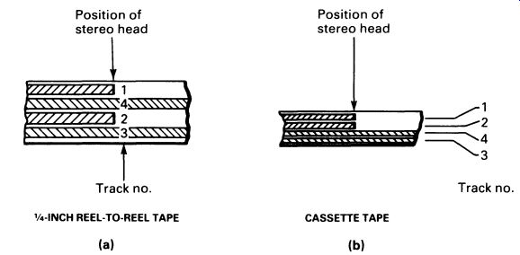
FIG. 7 track positions on reel-to-reel and cassette tapes; note
that the reel-to-reel tape records both pairs of tracks with a gap between
them, which simplifies head design to reduce 'crosstalk'; cassette tape-recorders
record tracks adjacent to one another, so that they can be replayed together
by a mono machine, easing the compatibility problem at the expense of
worsening crosstalk.
Technical advances have made it possible to obtain true hi-fi results from cassette tapes, which are both much cheaper and much more convenient than reel-to-reel tapes. Improvements in the tapes themselves have been a major factor, as has the improvement in electronics. And the introduction of Dolby® noise-reduction systems have lowered background noise to better than -70 dB, inaudible in practice. Dolby® noise-reduction techniques are very complicated, but in principle work by boosting the high frequencies when recording low-level sounds. At higher levels the high frequency boost is reduced, to avoid overloading the tape. During playback, a decoder system reverses the process, so high frequencies are attenuated to restore the correct balance to the recording-and along with them the back ground noise is attenuated as well. At higher recording levels, there is less improvement in background noise, but this is unimportant as the high-level sound masks the noise anyway. There are various implementations of the Dolby system, the most common being Dolby B and Dolby C. Extra ordinary improvements in background noise result, the two systems providing a noise reduction (in hiss, particularly) of 10 dB and 20 dB respectively.
1. TAPE DRIVE SYSTEMS
Along with an improvement in tapes and electronics has gone an improvement in the drive system used to transport the tape past the head. It should be evident that the tape must travel very smoothly past the head; any speed variations will alter the pitch of the playback. Slow changes in drive speed are known as 'wow', and rapid changes (which sound like someone gargling) are known as 'flutter'.
Fig. 8 illustrates a basic cassette recorder drive, omitting the extra pulleys and belts to provide fast forward and rewind.
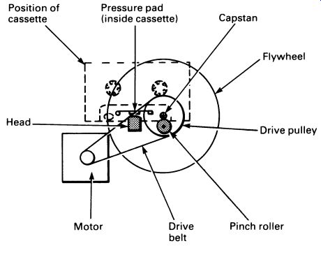
FIG. 8 a schematic diagram of a cassette tape drive mechanism (for
clarity, this illustration omits the extra drive necessary to rotate
the take-up reel of the cassette).
The motor, in battery-powered recorders, will often have an electronic speed control. The basic system for this is to have a generator fixed to the motor shaft, the generator producing a voltage that is more or less proportional to the speed of rotation of the shaft. An electronic circuit ( op-amp?) compares the generator voltage with a fixed reference voltage derived from a Zener diode. If the motor is going too fast, the generator voltage will be high, and the circuits will reduce the voltage to the motor. If, on the other hand, the generator voltage is low, the circuits will increase the motor voltage. Very accurate speed control can be obtained in this way, and the motor's running speed will be substantially independent of the battery voltage. This form of speed control is referred to as servo control. A system diagram is given in Fig. 9.
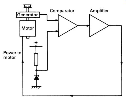
FIG. 9 electronic speed control of a motor using a feedback servo
system A heavy flywheel smooths out vibration from the motor, and provides
momentum to ensure that minor 'stickiness' in the cassette will not affect
the running of the tape. The tape is actually transported by a capstan,
against which the tape is held by a rubber pinch roller. The capstan
is always of small diameter, so that the flywheel can rotate fairly quickly,
and will always have a big leverage advantage against the tape.
2. VIDEO TAPE-RECORDING
The signal that provides the picture in a television can be recorded on tape in much the same way as an audio signal. It is, however, technically much more difficult to record a video signal because of the very large bandwidth: the recorder must reproduce very high and very low frequencies. This rules out the recording system used for audio, for a record head can only record a range of frequencies covering about 10 octaves (each octave doubles the frequency, so 10 octaves higher than 20Hz is 10.24 kHz). The system used is frequency modulation (see Section 15), which allows the required bandwidth of 18 octaves or more.
The second problem is reproducing the highest frequencies, around 5 MHz, at all. To record a single cycle of a waveform, a length of tape at least three times as long as the width of the record head gap must pass the head. Even with the finest heads, the required tape speed is very high indeed. Early video recorders, which operated like very large audio tape recorders, used tape speeds of up to 9 meters a second! The solution to this problem is the use of rotating heads. Two heads are mounted in a cylindrical drum, and the tape is wound round the drum at an angle. While the tape is pulled over the drum by the tape drive capstan, the drum spins at high speed in the opposite direction, the heads whizzing diagonally across about a foot of tape. This design is known as helical scanning.
Each complete scan across the tape is equal in time to one television field, which has the advantage that if the tape drive is stopped, but not the rotating drum, a still picture will be left on the TV screen.
An idea of the way helical scanning works can be obtained from Fig. 10. The tracks are very narrow indeed, for the more that can be cram med in, the longer the tape will play. On a domestic machine, the width of the tracks may be only about forty thousandths of a millimeter! The actual speed of tape through the machine is between 15 and 30 mm per second, according to the type of machine.
QUESTIONS
1. What is meant by 'bias' in relation to tape-recording?
2. Describe the function in a tape-recorder of (i) the erase head, (ii) the record/playback head, (iii) the flywheel.
3. Describe the symptoms you would expect in the case of failures in the following parts of a tape-recorder: (i) electronic speed control, (ii) ultrasonic bias, (iii) audio amplifier.
4. How can a video tape-recorder produce a still picture when the tape drive is stopped?
5. Why are noise-reduction systems more important in cassette tape recorders than in reel-to-reel recorders?
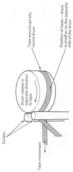
FIG. 10 helical scanning of a video tape provides a very high writing
speed, with a relatively slow tape transport speed