AMAZON multi-meters discounts AMAZON oscilloscope discounts
1. TOOLS
Soldering
Components are connected together in circuits by soldered joints. Solder is basically an alloy of lead and tin, the proportions varying according to the application. For electronics work a mixture of 60 percent tin and 40 percent lead is usual. If solder is heated to its melting point, and applied to a variety of different metals, it will amalgamate with the metal surface to provide a joint with high electrical conductivity and good mechanical strength--the strength is limited by the relatively poor tensile strength of the solder itself. Solder has a low melting point, lower than that of either tin or lead. The melting point varies according to the exact composition of the solder, but ordinary 60/40 tin/lead solder melts at 188°C. The temperature required to melt the solder is also sufficient to oxidize many metals, forming a layer of oxide that will prevent the solder 'sticking' to the surface. Solder inten4ed for electrical work is therefore made in the form of a hollow wire, with one or more cores of resin flux, a chemical mixture that will dissolve the oxide film at soldering temperatures. A cross section through two different makes of electrical flux-cored solder is given in FIG. 1. Solder can also be obtained in bar form, without the flux core.
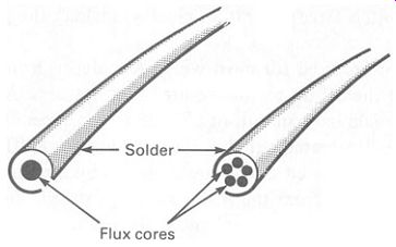
FIG. 1 two types of resin-cored solder.
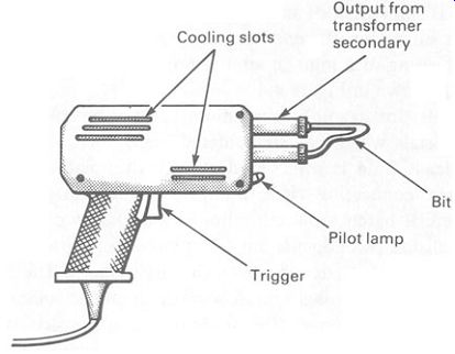
FIG. 2 a soldering gun-ideal for 'heavy' soldering and some kinds
of repair work.
For prototype and repair work, soldering is carried out using a soldering iron or soldering gun. The bit or tip of the iron is heated electrically to between 350 and 420°C. To make the joint, the bit of the iron is applied to the two surfaces to be joined, and the wire solder applied to the heated joint. The solder melts, allowing the flux to run over all surfaces and clean them. The solder also helps conduct heat from the iron on to the surfaces, and when the temperature is high enough it amalgamates with them. The iron can now be removed and the finished joint allowed to cool.
The means of heat generation is different in soldering irons and soldering guns. A soldering gun is illustrated in FIG. 2. The gun is basically a transformer. The secondary winding has a few turns of very heavy copper wire or bar, and generates a very heavy current at low voltage. The bit of the gun is made of copper, and, being substantially thinner than the transformer secondary windings, has a relatively high resistance. The energy generated by the transformer secondary winding heats the copper bit rapidly, until the soldering temperature is reached.
Soldering guns have the advantage that they are quick to heat up-only a few seconds- and cool down rapidly after switching off. The gun is on only when the trigger is held down. Soldering guns are also powerful, and are useful for soldering large components or small metal sheets. A typical soldering gun produces a heat output of some 50-150 watts.
The main disadvantage is that heat regulation is not particularly good, and it needs a certain amount of skill to keep the bit at the proper tempera ture. Also, the bit is large and rather clumsy, making the gun unsuitable for fine work.
Soldering irons are used for most work. A soldering iron uses a heating element to bring the bit up to the required temperatures. A small iron for electrical work would have an output of 7-25 watts, depending on size; for delicate work (e.g. integrated circuits) about 10 watts is sufficient.
Some types of integrated circuit are damaged by the slightest electrical leakage of high voltage from the mains supply, through the insulation of the iron (or through internal capacitance). To reduce this danger, ceramic shafted soldering irons are available, in which a thin ceramic sleeve insulates the bit from the rest of the iron. The sleeve has excellent insulating proper ties and low capacitance, and provides a good measure of safety when soldering sensitive circuits. A sectional drawing of a ceramic-shafted solder iron is given in FIG. 3.
Soldering is something of an art, and needs to be practiced. Typical bad joints are caused by insufficient heat, dirty surfaces, insufficient solder or persistent reheating of a joint in an attempt to get it to stick. A selection of problems is shown in FIG. 4.
Some metals-for example, aluminum--cannot be soldered by normal techniques. Metals which can be soldered easily include gold, silver, tin, copper and lead. Gold is often used as very thin plating over copper or iron component connecting wires, to improve solderability.
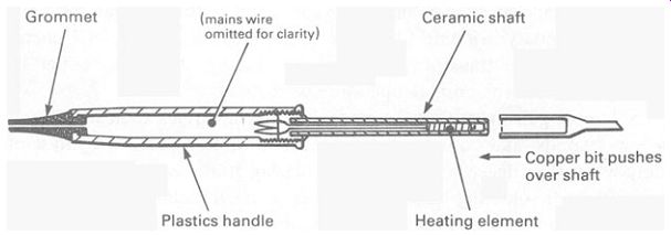
FIG. 3 a ceramic shafted soldering iron, used for light soldering
jobs, especially where circuits that are sensitive to electrostatic voltages
are being soldered
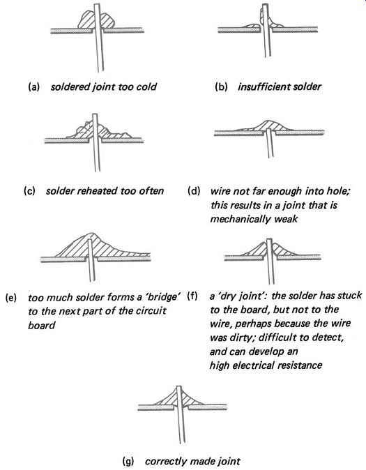
FIG. 4 some soldered joints, in cross-section -------- (a) soldered
joint too cold (c) solder reheated too often (b) insufficient solder
(d) wire not far enough into hole; this results in a joint that is mechanically
weak (e) too much solder forms a 'bridge' (f) to the next part of the
circuit a 'dry joint': the solder has stuck to the board, but not to
the wire, perhaps because the wire was dirty; difficult to detect, and
can develop an board high electrical resistance (g) correctly made joint.
In commercial batch production lines wave soldering is often used. In this system, all the components are first placed in position in the printed circuit board, and the leads cut off to the right length. The whole circuit board is then moved across a special soldering bath, to solder all the component connections at once. The soldering bath consists of a bath of molten solder, pumped over a baffle in such a way that a standing wave is produced, making a 'hump' in the surface of the molten solder. The bottom of the circuit board is passed over the hump, and solder sticks to the board and the components but not to the areas of plastic or varnish that are not required to be soldered. The mass of the solder is of course ample to hold sufficient heat to bring the component connections and the copper leads up to soldering temperature almost immediately.
Desoldering
Usually a component can be heated up with the soldering iron and the connections pulled apart. In some cases this is not practicable, for example where an integrated circuit is soldered directly into a printed circuit. All the pins-as many as forty-would have to be heated up simultaneously before the component could be removed from the board. To assist in removing this sort of component, a solder sucker is used. A solder sucker is illustrated in Figure 45.
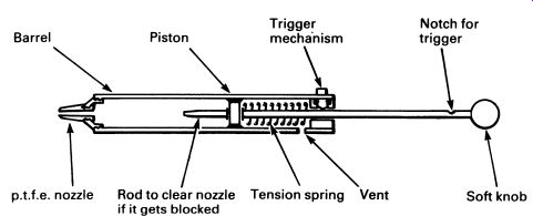
FIG. 5 a solder sucker; the nozzle is made of polytetrafluoroethylene
(p. t. f. e.), a plastic that is resistant to heat and to which molten
solder will not stick.
The principle is very simple, rather like a back-to-front bicycle pump.
The plunger is pushed down against the spring, where it is locked by the trigger. The soldered joint to be released is then heated with a soldering iron, the nozzle of the sucker applied to it, and the trigger pressed. The spring forces the plunger up the tube, sucking the molten solder up after it and also cooling it instantly. Some solder suckers have a double-sprung plunger to prevent it flying out and hitting you in the face when you press the trigger.
Hand tools
A range of small hand tools is used for electronics work, but there are few specialized tools. A variety of long- and short-nosed pliers should be avail able, as well as small and medium side-cutters. Several screwdrivers, both flat and cross-point, are essential. The only specialized tools that are often found are wire strippers, for removing the insulating plastic from connecting wires; trim tools, small plastic screwdrivers for adjusting the cores of inductors; and perhaps a miniature electric drill and magnifying glass.
In some high-quality assembly and prototype work, an assembly technique known as wire wrapping is used; there are a number of special devices to be used, for wrapping and unwrapping wires. Briefly, wire wrapping consists of making a connection by wrapping a wire tightly round a hard square post with sharp comers. This results in a joint with good mechanical and electrical properties, made without heat.
2. TEST EQUIPMENT
The multimeter If the electronics engineer is to have any idea at all of what is going on in circuits, a range of instruments must be available for measuring the various quantities involved. The multimeter is the electronic engineer's most basic tool, and has been developed as a quick and easily used means of measuring basic electrical quantities.
A multimeter consists of a measuring device, plus associated circuits to select a suitable range and function.
The range and function controls are made to be as convenient as possible for ease of use. A good multimeter might have the following functions and ranges:
Direct voltage
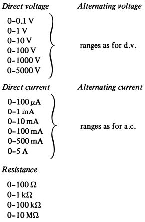
Multimeters from different manufacturers will have rather different ranges, but the above gives an idea of what is average in a good-quality meter.
There are other factors, besides ranges, which need to be taken into account. One is the input resistance. It is no good having a meter which reads voltage if the meter itself imposes a heavy load on the circuit that it is measuring and changes that voltage. Similarly, a meter to measure current should place as little series resistance as possible in the circuit being measured, or the measurement will prove unacceptably lower than the current that flows without the meter. When measuring resistance, which requires a current to be passed through the thing being measured, the current should not be too great or the applied voltage too high.
All the above factors are a function of price-in general, the more you pay, the better the specification.
Analog and digital
Traditionally, multimeters were made using high-quality jeweled meter movements, made to the finest engineering tolerances. Today, such meters are still available but there is an option to use a digital display instead.
For most purposes, the digital meter is the better option. A typical digital meter has a '3f digit' display, meaning that it can display any number between 0000 and 1. 999. This type of display is used because it virtually doubles the range with only a little extra electronics.
The digital meter is usually more accurate and more robust than the mechanical 'analogue' meter, price for price. It is, however, less suitable for measuring continuously changing quantities than the analog meter where the meter needle can swing to and fro with the changes to indicate roughly what is happening (following a 1 Hz waveform, for example), the digital meter becomes a confusion of changing figures.
For details of the principles of the analog meter, see Section 17; and for details of digital meters, see Section 23.
The oscilloscope
The cathode ray oscilloscope (CRO) is probably one of the most useful items of test equipment, after the multimeter. The CRO uses a cathode ray tube (see Section 5) to display the waveform of an electrical voltage. The tube is a precision device, and is designed so that the electron beam (producing the spot on the screen) can be deflected by an accurately controlled amount. The screen is ruled with a grid of squares, called a graticule, and is arranged like a graph, with a vertical y-axis and a horizontal x-axis. A typical CRO screen layout is given in FIG. 6.
The grid is conveniently ten squares in both directions. The (horizontal) x-axis is calibrated in time, and they-axis is calibrated in voltage. Both the time scale and the voltage scale are adjustable, by means of range-setting controls. A small general-purpose oscilloscope is illustrated in the photo graph in FIG. 7.
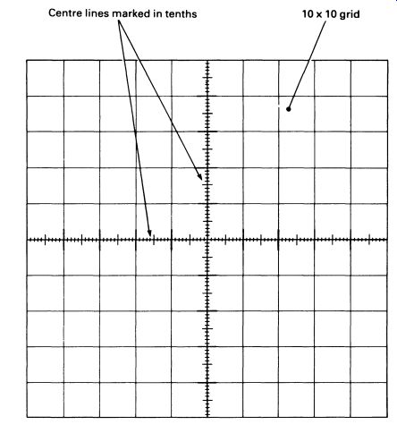
FIG. 6 an oscilloscope graticule.
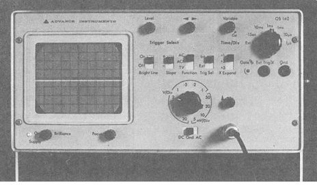
FIG. 7 a typical small oscilloscope.
The x-axis is calibrated in 'time per division', making the spot scan the screen at a rate controllable from a maximum speed of 1 p.s per division to a minimum of 0.1 s per division. The range-setting control is in the top right of the front panel.
In the center of the lower part of the panel is the control for setting the range of the y-axis. This is variable, in this particular model, in twelve steps from a maximum sensitivity of 5 m V per division to a minimum sensitivity of 20 V per division. The control for this is in the middle of the lower part of the photograph.
A graph of almost any electrical waveforms can be displayed on the screen, providing an invaluable aid to understanding circuit function or to servicing most electronic equipment.
A most important feature to be found on the oscilloscope is the trigger or synchronization system. Circuits in the instrument detect the level of the signal being measured, and trigger the sweep of the x-axis (at the set rate) at a predetermined point in the waveform. Because the sweep is always triggered at the same point on the waveform, the picture on the screen is automatically 'locked' in place on the screen, and does not drift from side to side with small changes in frequency. Provision may be made to trigger the sweep of the x-axis from an external source, perhaps derived from the circuit under measurement. Additionally, there may be special-purpose filter circuits built into the CRO to select, for example, television synchronization signals (see Section 15) and lock the picture on to them. A range of such facilities can be seen in the photograph.
The CRO can, of course, be used as a measuring instrument, as the 'graph' on the screen is accurately calibrated. Voltage can be measured by reference to the y-axis, and frequency or pulse-widths by reference to the x-axis.
A good oscilloscope is not cheap, and the more expensive units will have better accuracy, more facilities and greater range. Oscilloscopes designed to work at high frequencies also tend to be expensive, as do CROs designed specially for digital work. A good one may cost as much as a family car.
The more expensive models have a double-beam tube, which displays two waveforms simultaneously. The x-axes are synchronized with each other, but the y-axes are controlled by independent inputs. This facility permits of comparison of waveforms-to test a divider or pulse-shaping circuit, for example.
The signal generator
The signal generator is an instrument for producing a waveform at a known frequency, and having a known shape. Most signal generators can provide a sinewave output or a squarewave output, with a peak-to-peak voltage ranging from a few millivolts to a few volts. Frequencies from a few Hz to a few MHz are standard in an inexpensive instrument, and it is often possible to produce an output that is a radio frequency carrier, modulated with an audio signal (see Section 15). The better signal generators will also produce output pulses that are compatible with digital logic circuits (see Sections 20 and 21), with both the pulse-width and frequency independently variable.
The transistor tester
Oddly, it is seldom necessary to test a transistor. Reference to the manufacturer's specifications or a simple substitution are usually all that is necessary. It is, however, possible to buy instruments that will measure a transistor's parameters accurately. Such instruments are, in fact, seldom used, except in the laboratory. Somewhat more useful are in-circuit transistor testers, which can perform a 'go/no go' test on a transistor without the necessity for removing it from the circuit it is fitted into. Such devices are useful servicing aids.
3. SAFETY
Safety in using test equipment
This refers to the safety of the equipment, not the safety of the wielder of it! It is always possible to devise a way of damaging or destroying completely an item of test equipment, despite all the safety devices the manufacturers have built into it. Often such ways are discovered accidentally by engineers and students who should know better.
Always, always, make sure that you have selected a suitable range before connecting a meter or CRO to a 'live' circuit. Don't expect to be able to set a meter to read full scale 10 mA and then connect it across a mains supply without a flash and a bang and an expensive repair bill.
Oscilloscope input amplifiers can be wrecked in the same way, by selecting a range that is far too low-and the repair bill for even a cheap oscilloscope will amaze you-adjusting and recalibrating a CRO is labor-intensive and therefore costly.
Remember that while little damage will be done by connecting a meter set to read volts in series with a circuit (expecting to read current), you must be very careful not to select a current range and then try to read a voltage. The low resistance of the meter will result in all the available current flowing through the meter ... if the meter has a fuse or automatic cutout, you might be lucky .... The same applies to measuring resistance.
Never try to use a resistance range on a circuit that is live. At best the results will be suspect, at worst you will destroy the meter. Remember, too, that 'live' can mean a charged electrolytic capacitor in a circuit that is disconnected from its power supply.
Finally, it is wise to remember the remark of the salesman who, when asked the working life of his company's latest digital multimeter, replied 'Until you knock it off the workbench.' General safety The trouble with electricity is that you can't see it, smell it, or hear it.
You can, however, feel it. And in the right (or wrong) conditions, it can kill you.
In the UK the Health and Safety at Work Act 1974 places the responsibility for people at work on the employer and the employee. In other words, although your employer has a duty to make sure that working conditions are as safe as is reasonably possible, it is up to you to take care of yourself.
Most serious injuries and deaths from electric shock occur from contact with the mains electricity supply, which in the UK is around 240V a.c.
The live wire of the mains supply is at a high voltage with respect to earth, and if you are touching the ground you can receive a fatal electric shock by touching the live wire only. Because electric shock kills by temporarily paralyzing the heart muscles, the greatest danger occurs when the current flow is across the chest-either from one arm to the other, or from either arm to either leg.
The resistance of a human body depends mostly on the resistance of the skin. If the skin is damp, either from water or from perspiration, the resistance is dramatically reduced. In such circumstances the chances of any electric shock being a fatal one are greatly increased, so you should never operate or touch electrical equipment with wet hands.
The secondary effects of electric shock can also be dangerous. A television engineer was seriously hurt when he was fitting a loft aerial.
His assistant plugged the aerial into a faulty television receiver (it had been modified by an amateur 'expert') and the aerial became live to the mains. The shock threw the engineer off the joist he was standing on; he fell through the plasterboard ceiling and came down astride an open door.
Electronics engineers run special risks when dealing with apparatus that uses high voltages. COLOR-television receivers use very high voltages up to 30kV-at relatively high currents. Contact with a color television EHT (extra high tension) connection is usually fatal.
Apparatus designed to be connected to the mains should either be earthed or double insulated. These precautions greatly improve the safety of the equipment, but not if you take the covers off for working on the insides. FIG. 8 compares the way the two methods of protection work for faulty equipment.
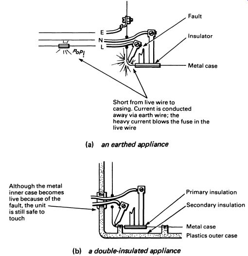
FIG. 8 (a) an earthed appliance ; (b) a double-insulated appliance.
An isolation transformer provides a measure of safety when working on equipment that requires mains voltage. The isolation transformer is a transformer with two separate windings, insulated from each other to a high standard. The windings have a turns ratio of 1: 1, so that the output voltage is the same as the input voltage. Safety is improved because neither of the two supply wires is live with respect to earth. Touching just one or the other will not result in a shock. The voltage is still just as high, however, so all the usual precautions should be taken.
Take extra care when switching off or isolating circuits, particularly mains. Anyone can make mistakes. I am lucky to have written this guide, for a few years ago I was working on a mains line. The line was controlled by a double-pole isolating switch of approved design. Before starting, I checked that the switch was off, double-checked in fact. I then took my cutters and carefully cut the wire on the wrong side of the switch. It cost me a good pair of cutters, but it could easily have cost a lot more.
Fire is always a danger. Electrical equipment of all types dissipates heat, and under fault conditions the heat output of a component can rise high enough to cause a fire. I once saw a color television with most of its insides and part of the cabinet completely devastated by a fire caused by a faulty capacitor. The capacitor short-circuited and overloaded a 1 kilowatt resistor. The resistor overheated and melted a plastic insulating sleeve over high voltage connections to the back of the tube. This caused a massive short-circuit, which set fire to the whole receiver. The owner was fortunate that the fire confined itself to the television.
Various types of fire extinguishers are available-and it should go with out saying that water should never be used in an attempt to put out an electrical fire. Fires are extinguished by removing the combustible material seldom possible--or by removing the oxygen supply, or by cooling the burning material below the point at which combustion can be sustained.
Foam extinguishers work by smothering the fire in a foam containing the inert gas carbon dioxide and depriving it of oxygen. However, they contain water and are unsuitable for electrical fires.
Carbon dioxide extinguishers contain liquid carbon dioxide gas, which smothers the fire with inert gas and starves if of oxygen. This type of extinguisher is good for fires of all types, especially electrical fires. Although the gas is very cold as it comes out of the nozzle, it has little cooling effect by the time it reaches the flames and the fire may re-ignite if the gas is blown away or begins to dissipate. Carbon dioxide extinguishers are also suitable for burning liquids.
Dry powder extinguishers are useful for electrical fires, especially fires that are fairly confined-such as a burning item of equipment. The dry powder does no damage and can be brushed off, so there is more chance of salvaging apparatus that has been extinguished with this type of appliance. Dry powder extinguishers are not suitable for large fires.
Fire blankets are very effective. They are usually made of aluminized glass-fiber cloth and are simply placed over the burning object to deprive the fire of oxygen. This does mean going right up to the fire, so be careful.
Sand also works quite well, but should not be used on burning liquids as it simply spreads them around.
It is important that you only tackle a fire (i) if you think it is small enough to put out-don't overestimate the power of even large extinguishers; (ii) if there is no personal danger; (iii) after you have raised the alarm. If a piece of equipment, or even a whole room is ablaze, shut the door. This will slow the fire's spread, even if the door is an ordinary plywood interior door. It will also slow the spread of smoke and possible toxic fumes, potentially more dangerous than the fire itself.
As a preventative measure, don't leave equipment running if there is nobody about, and make sure that all fire doors, fire escape routes and fire appliances are in usable condition.
4. FIRST AID
This is not a guide on first aid, and there are many excellent books on the subject available at bookshops and chain stores. Buy one and read it.
The special hazard in electronics and electrical work is shock. Remember that shock kills by paralyzing the heart and sometimes the respiratory muscles. If you can keep a victim alive for a few minutes, the chances of complete recovery are good.
When attempting to help someone who is the victim of electric shock, make certain that the cause of the shock has been removed before you touch the victim. Otherwise you may become the second victim.
If there is a mains switch nearby, cut the power. If this is not possible, use an insulator to get the person away from the power. A broom handle, wooden or plastic chair, improvised rope (your shirt, a rug, jacket, etc.), will do. If the victim is holding the source of the shock, it may take force to make him let go, since the electricity contracts the muscles of the hand.
If the victim is unconscious, check to see if breathing continues. If not, mouth-to-mouth artificial respiration should be begun. If the victim does not start to breath spontaneously, check for heartbeat-listening to the bared chest is the easiest way-and if you cannot detect a heartbeat or see a pulse beating in the victim's neck, then begin cardiac massage. The techniques are described in any good first-aid book. Remember that the brain cannot survive more than three or four minutes without a supply of oxygenated blood, so don't waste time.
If all this makes electronics sound very hazardous, the good news is that modern circuits tend to use low voltages rather than high voltages.
With a few exceptions-portable televisions and electronic flashguns, for example--battery-powered equipment is unlikely to give the careless engineer a shock. But it pays to be careful. If in doubt, don't touch.
QUESTIONS
1. You want to measure, approximately, the frequency of a signal. A frequency measuring meter is not available. What item of test equipment would you use?
2. Unfortunately the item of test equipment used in the above question suddenly bursts into flames. Describe the correct procedure for dealing with this emergency.
3. Why is double-insulated equipment safe without an earth connection?
4. Which of the following metals might prove difficult to solder: tin, copper, aluminum, brass, gold, steel.
5. What are the maximum and minimum voltages that can be read on a good 3-1/2 digit digital voltmeter?