AMAZON multi-meters discounts AMAZON oscilloscope discounts
The components used in electronic circuits are divided into two main classes. These are referred to as 'active' and 'passive' components. Active components use the movement of electrons either through a vacuum or through a semiconductor to perform some function in the circuit. Passive devices, on the other hand, do not control the movements of the electrons, but rather allow the electrons to flow through them. It could be argued that the simplest of all passive devices is a length of wire!
1. RESISTORS
Resistors are components intended to insert a known amount of resistance into an electrical circuit. As we saw in the last section, they are available in a range of different values and tolerances. It will also be evident to anyone who has looked at an electronic circuit that they are also available in a range of sizes. The sizes relate to the amount of power that the resistor can dissipate. An electric current passing through a resistor will always cause a certain amount of energy to be dissipated as heat. The amount of energy dissipated can be calculated by the simple formula: P= VI watts where P represents power.
Let us consider the case of a 5 ohm resistor connected across a 12 volt battery. This is illustrated in FIG. 1. We can use Ohm's Law to calculate the amount of current flowing through the resistor. This is given as: I= '!': R
It is clear that the voltage, when measured across the resistor, must be equal to the battery voltage, provided we neglect any resistance in the wires. We can now use the formula to calculate the amount of power that the resistor is dissipating as heat:
P= VI
P=12x2.4
P = 28.8 watts
28.8 watts is a respectable amount of heat-the above calculation might be made for a car's rear-window heating element. It is quite obvious that a tiny component such as a resistor one might find in an electronic circuit could not possibly dissipate this much heat without damaging itself. In fact, a resistor designed to dissipate around 30 watts would be quite large--perhaps 5 em long. It would also be made in such a way that the body of the resistor could become quite hot. In practice, the designers of most electronic circuits try to avoid such large heat outputs which can cause problems in cooling the equipment.
Resistors used in electronic circuits are designed with power dissipations of 0.25, 0.5 or 1 watt. Larger sizes are available, but are less commonly used.
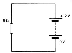
FIG. 1 power: a simple circuit like this will dissipate heat.
The same formula as the one above is used to calculate the power dissipation of series and parallel combinations. FIG. 2 shows such circuits. FIG. 2a illustrates two resistors connected in series. It is quite clear that the same current flows through both resistors. However, when measured across each resistor, the voltage will be different. The total potential difference is given as 5 volts. We can find the voltage across each individual resistor by using Ohm's Law. We know that the total resistance of the circuit is 3.2 k ohm and can use Ohm's Law to calculate that the current flowing through the circuit is about 1.562 mA. Using the form of Ohm's Law V = IR, we can calculate the voltage drop across each resistor. For the first resistor: And for the other resistor: V= 1000 x 1.562mV V= 1.562 V = 2200 X 1.562 V=3.44 Now that we know the voltage dropped across each resistor we can calculate the amount of power that each resistor is dissipating. For the 1 k-Ohm resistor this is: p = 1.562 X 1.562 P=2.43mW. And for the 2.2 k-Ohm resistor the power dissipated is given as: P= 1.562 X 3.44 P= 5.37mW. Look carefully at the units used in these calculations! The amounts of power dissipated are very small, typical, in fact, of the sort of thing we will become used to in electronic circuits. The smallest commonly avail able size of resistor (0.125 watts) is substantially larger than is necessary to dissipate this amount of power.
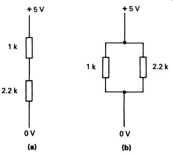
FIG. 2 resistors in series and in parallel.
Exactly the same kind of calculation is used to work out the power dissipations in resistors in parallel. In this case-illustrated in FIG. 2b the voltage across both resistors is the same (5 V), but the current is different. We can use Ohm's law to ascertain the current flowing through each resistor, and arrive at 5mA and 2.27mA for the 1 k-Ohm and 2.2k-Ohm resistors respectively. We can now use our power calculation to determine that the 1 k-Ohm resistor is dissipating 5 x 5 = 25 mW. The 2.2 k-Ohm resistor is dissipating 2.27 x 5 = 7.35 mW. If you are in any doubt about this calculation, work ft out on a piece of paper. Another, equally valid way of working out power dissipations in series or parallel combinations of two resistors is to calculate the total dissipation of the pair (very simply done) and then use a ratio calculation to determine how much power is dissipated by which resistor. Note that in series combinations it is always the resistor with the higher value that dissipates the most power. In parallel combinations, it is the resistor with the lower resistance that dissipates more power.
Before leaving resistors, we should look at the physical structure of the three main types of resistor. These are all electrically comparable-there is only one kind of resistance-but they are mechanically different, being suitable for slightly different applications.
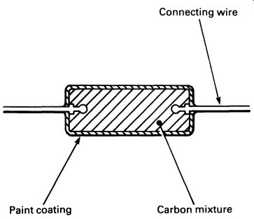
FIG. 3 a solid carbon resistor (this component might be anything
from a few millimeters to a few tens of millimeters long).
Types of resistor
The most usual type of resistor is the solid carbon resistor (see FIG. 3). Its structure is very simple, consisting of a small cylinder of carbon which is mixed with a non-conductor. A connecting wire is fixed into each end, and the resistor is given a coat of paint to protect it from moisture which might alter the resistance.
Resistors are always marked with a color code to indicate the value.
The color code consists of three or four colored bands painted round the resistor body. This system is used because it makes the resistor's value visible from any direction-a printed label could be hard to read with the component in place on a crowded board. Also, a painted or printed value could easily get rubbed off, whereas painted-bands are relatively permanent.
The first three bands of the color code represent the value of the resistor in ohms. Bands 1 and 2 are the two digits of the value, and band 3 represents the number of zeros following the first two digits. FIG. 4 gives the resistor color code; the standard is international. The fourth band is used to indicate the tolerance of the resistor's stated value.
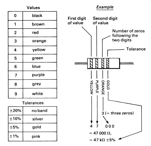
FIG. 4 the international standard resistor color code
Where values of resistance less than two digits are required, the two bands are followed by a gold band. Thus 4.7 ohm would be represented as yellow, purple, gold, plus a tolerance band.
The next kind of resistor is the metal oxide or metal glaze resistor. This looks rather like the carbon resistor from the outside, but the internal structure is-different. FIG. Sa shows a cross-section.
Metal oxide resistors can be made to closer tolerances than carbon resistors, and change their resistance less with changes in temperature. For this reason they are sometimes called high-stability resistors. The resistance of a metal oxide resistor changes by approximately 250 parts per million per °C. This compares with about 1200 parts per million per °C for carbon resistors.
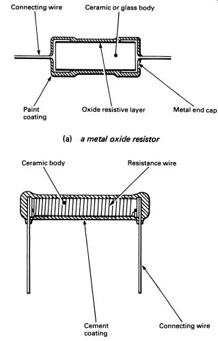
FIG. 5 (a) a metal oxide resistor; (b) for high power applications,
a wire-wound resistor is used.
Both carbon and metal oxide resistors are made in a range of stock sizes, from about 0.125 W dissipation to about 3 W. Sometimes it is necessary to have resistors that can cope with higher powers; for this, wire wound resistors are used. The wire-wound resistor is shown in FIG. 5b.
It is easy to make wire-wound resistors in low resistance values, down to fractions of an ohm. High resistance values use wire of low conductivity, requiring many turns of fine gauge wire as well. The maximum practical value for a wire-wound resistor is a few tens of kilohms, at least for components that are a reasonable size. Power ratings range from 1-50W in the stock sizes; there is no limit to the size in practice, and larger special purpose wire-wound resistors are common.
It is possible to make precision wire-wound resistors in which the resistance is specified to a very close tolerance, within± 0.1 percent. Such resistors are expensive and would be used only in measuring equipment.
Variable resistors
For applications such as volume controls and other 'user controls' in electronic equipment, it is often necessary to have a resistor that can be altered in resistance by means of a control knob. Such resistors are called variable resistors, or potentiometers. They consist of a resistive track, made with a connection at either end. A movable brush, generally made of a non-corroding metal, can be moved along the track; an electrical connection to the brush allows a variable resistance to be obtained between either end of the track and the brush.
Three forms of variable resistor are shown in FIG. 6b. Note that the shaft (or slot) that moves the brush is generally connected to the brush; it is important to know this for safety reasons.
Variable resistors are available in various shapes and sizes, with power dissipations from around 0.25 W upwards. Tracks are either carbon, conductive ceramic ('cermet') or wire-wound. Resistance ranges are available between fractions of an ohm and a few megohms.
The track can be made in such a way that the resistance increases smoothly along the track-the usual, linear, type of potentiometer. For some audio uses (such as volume controls) logarithmic potentiometers are made in which the resistance increases according to a logarithmic law rather than a linear law. For most purposes you need only remember that the way logarithmic potentiometers control volume approximates the way the human ear responds to sounds of different loudness. If you use a linear potentiometer for a volume control, the effect of the control seems to be 'all at one end' of the scale.
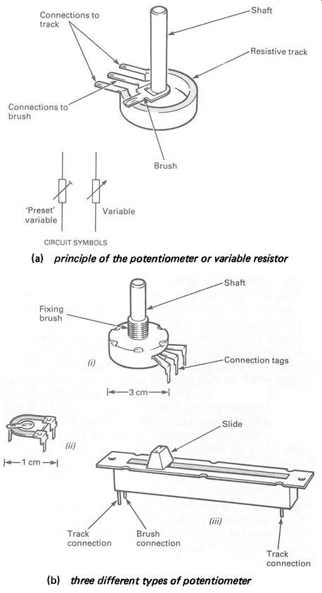
FIG. 6 (a) principle of the potentiometer or variable resistor ;
(b) three different types of potentiometer
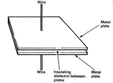
FIG. 7 schematic view of a capacitor
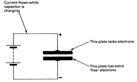
FIG. 8 a capacitor connected to a power supply; current will flow
until the capacitor is charged.
2. CAPACITORS
Next to resistors, the most commonly encountered component is the capacitor. A capacitor is a component that can store electric charge. In essence, it consists of two flat parallel plates, very close to each other, but separated by an insulator (see FIG. 7). When the capacitor is connected to a voltage supply, a current will flow through the circuit (see FIG. 8). Electrons are stored in one of the plates of the capacitor; in the other there is a shortage of electrons. In this state the capacitor is said to be charged, and if it is disconnected from the supply, the imbalance in potential between the two plates will remain.
If the charged capacitor is connected in a circuit, it will, for a short time, act as a voltage source, just like a battery. This can be demonstrated quite nicely with nothing more than a large capacitor, a 9 V battery such as PP9, and a capacitor rated at 10 V, 1000 uF (see below regarding units of capacitance). Note that the capacitor will be an electrolytic type (again, see below) and must be connected to the battery with its + terminal towards the positive ( +) terminal of the battery. The demonstration is shown in FIG. 9.
Try the experiment again, this time allowing two minutes between charging the capacitor and discharging it into the bulb. Try waiting progressively longer, and you will see that the charge gradually leaks away on its own. This is due to the imperfection of the insulator separating the plates, allowing a tiny leakage current to flow.
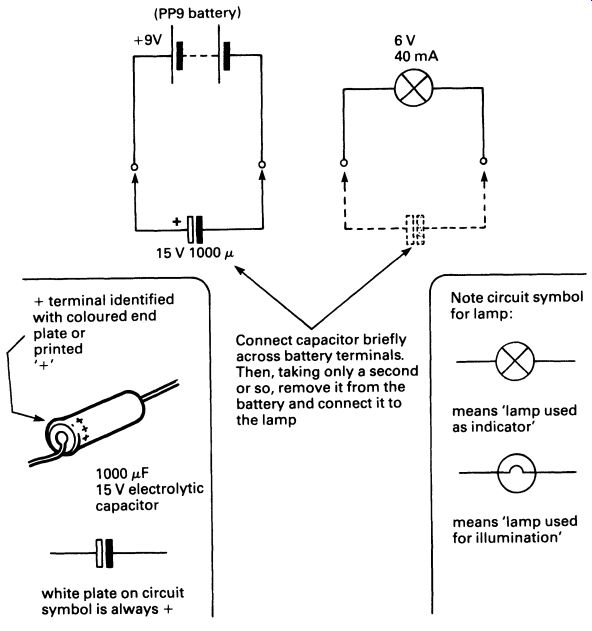
FIG. 9 a simple experiment for demonstrating the way in which capacitors
can store power; a large capacitor is first charged up from a 9 volt
supply, and then discharged into a small/amp
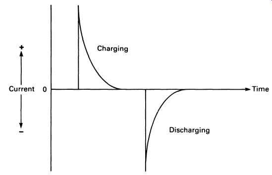
FIG. 10 a graph showing a capacitor charging and discharging
A graph of the current flowing through a charging and then discharging capacitor is compared with the voltage measured across it in FIG. 10.
The unit of capacitance is the farad, named after Faraday. One farad is a very large unit of capacitance, in the context of electronic circuits, and the smaller derived units of capacitance are used. The largest practical unit is the microfarad, symbol uF. Although values of capacitance in the range of thousands of microfarad are sometimes used, the milli-farad is never encountered-a capacitor would be marked 10 000 uF, for example, not 10 mF. If you do see a capacitor marked 'mF', it is almost certainly meant to be uF, with that manufacturer (Far Eastern?) using a non-standard abbreviation. In addition to the uF, the nF and the pF are commonly used units.
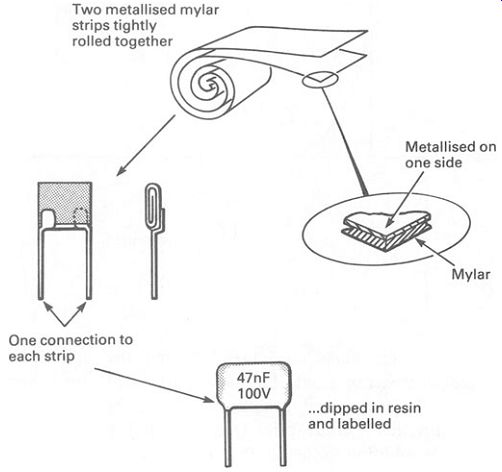
FIG. 11 a typical capacitor, used in electronics work-the 'metallized
film' type.
There are many different types of capacitors, according to the use to which the component is to be put, and also to the operating conditions.
The capacitance of the component is determined by three factors: the area of the plates, the separation of the plates, and the insulating material that separates them, known as the dielectric. For the same dielectric material, the closer and larger the plates, the greater the capacitance. Another factor determines the thickness of the dielectric, and that is the maximum voltage to which it is going to be subjected. If the dielectric is very thin, it will break down with a relatively low voltage applied to the plates of the capacitor. Once the dielectric has been damaged, the capacitor is useless.
High voltage capacitors need thicker dielectrics, to withstand the higher voltage. To produce the same capacitance, the plates have to be larger in area-so the component is bigger.
The simplest type of capacitor uses a roll of very thin aluminum foil, interleaved with a very thin plastic dielectric such as mylar. A physically smaller capacitor can be made by actually plating the aluminum on to one side of the mylar (see FIG. 11). For higher voltages, polyester, poly styrene or polycarbonate plastic material is used as the dielectric.
Ceramic capacitors are used where small values of capacitance and large values of leakage current are acceptable-the ceramic capacitor is inexpensive. A thin ceramic dielectric is metallized on each side, and coated with a thick protective layer, usually applied by dipping the component.
Both plastic film and ceramic capacitors are available in the range 10pF-1 uF, though plastic film types may be obtained in larger values.
Where really high values of capacitance are needed, electrolytic capacitors are used. Electrolytic capacitors give very large values of capacitance in a small component, at the expense of a wide tolerance in the marked value (-25 to +50 percent) and the necessity for connecting the capacitor so that one terminal is always positive.
The most commonly used type of electrolytic capacitor is the aluminum electrolytic capacitor. The construction is given in FIG. 12. After manufacture, the capacitor is connected to a controlled current source which electrochemically deposits a layer of aluminum oxide on the surface of the 'positive' plate. The aluminum oxide makes an excellent dielectric, with very good dielectric strength (resistance to voltage applied across the plates). Since the layer is chemically deposited it is very thin.
The electrolytic capacitor must not be subjected to voltages applied in the wrong direction, or the aluminum oxide layer will be moved off the positive plate, and back into the electrolyte again.
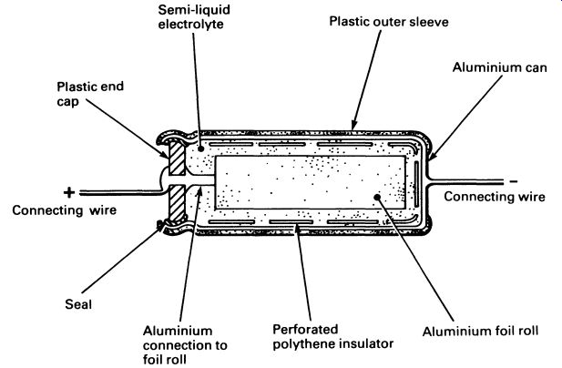
FIG. 12 construction of an aluminum electrolytic capacitor
Variable capacitors
Capacitors are made that can be varied in value. Either air or thin mica sheets are used as the dielectric, so the capacitance of variable capacitors is usually low. Rotary or compression types are made. In the former, the capacitance is altered by changing the amount of overlap of the two sets of plates; see FIG. 13a. In compression trimmers, the spacing between plates is altered, as in FIG. 13b.
Variable capacitors can be obtained with maximum values from 2 pF to 500 pF.
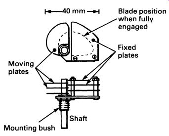
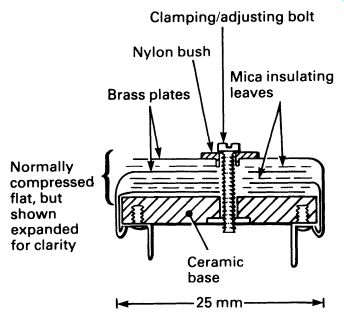
FIG. 13 (a) a variable capacitor of the 'air space' type (this component
would be used for tuning a radio receiver, for example) ; (b) a 'compression
trimmer', a form of variable capacitor used to preset circuit values
(adjustment is by means of a screw)
Capacitors as frequency-sensitive resistors
Once a capacitor has charged up, it will not pass current when connected to a direct voltage supply. However, if we reverse the polarity of the supply, the capacitor will permit a current to flow until it has charged up again, with the opposite plates positive and negative. The capacitor will then, once again, block the flow of current. If the frequency of an alternating voltage applied to a capacitor is high enough, the capacitor will actually behave as if it were a low value resistor, as it will never become charged in either direction. At lower frequencies, the capacitor will appear to have a higher resistance, and at zero frequency ( d.c.) it will, as we have seen, have an infinitely high resistance if you disregard the leakage current.
The precise value of resistance shown by the capacitor will depend upon the capacitance, the applied voltage and the frequency. The property is known as reactance. It enables the circuit designer to use the capacitor to block or accept different frequencies in a variety of different circuit configurations, many of which you will meet later in this guide.
Capacitors in series and parallel Capacitors can be used in series and in parallel. When used in series, the working voltage is the sum of the two working voltages, so two capacitors intended for a 10 V maximum supply voltage could be used, in series, with a 20 V supply.
The calculation of capacitor values in series and parallel is similar to the calculation used for resistors in series and parallel, but in the opposite case.
Thus for capacitors in parallel the formula:
C=C1 +C1 +C3 + ... is used, simply adding the values together. For capacitors in series:
1 1 1 1
-=-+-+-+ ... c c. cl c3
gives the total value of capacitance.
Unfortunately, there is no internationally agreed color code for capacitors, so manufacturers usually stamp the value on a capacitor, using figures in the normal way. A few capacitors are marked with colored bands, but it is wise to look at the maker's catalog to check what the code means.
3. INDUCTORS
The third major passive component is the inductor. This is a coil of insulated wire that may, or may not, be wound over a ferrous metal former.
When a coil is connected in a circuit, as in FIG. 14, the flow of current through the coil causes an electromagnetic field to be created around the coil. Building the field absorbs energy, and the electromagnetism produces its own current in the coil, opposing the direction of the applied current.
The effect is that, when current is first applied to the inductor, it seems to have a high resistance, reducing the current flow through it. Once the electromagnetic field is established, the resistance drops. A graph of the current flowing through an inductor, and the voltage measured across it, is given in FIG. 15.
Compare this graph with the one in FIG. 10, and you will see that the inductor is the 'opposite' of a capacitor! Once the current flowing through the inductor is constant, the only opposition to current flow comes from the resistance of the coil wire-usually small compared with the apparent resistance (called inductive reactance) when the current is building up.
The opposing force that prevents current flowing right away is induced current, trying to flow the opposite way. We can make great use of this phenomenon in constructing a transformer.
The unit of inductance is the henry, symbol H. In electronics, mH and u1H are commonly found, but the henry, like the farad, is rather a large unit.
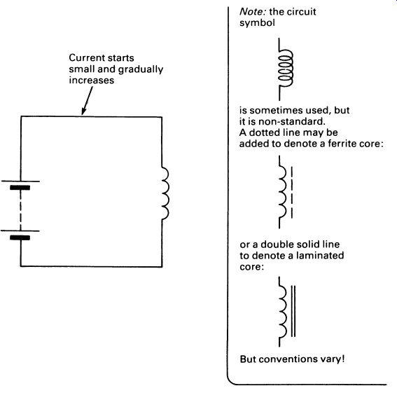
FIG. 14 an inductor connected in a simple circuit; the current rises
to a fixed level, determined by the resistance of the inductor's windings.
Inductors are available as a range of components, in small inductance values from a few uH to a few mH. However, there are so many variable factors that a 'stock range' of all required types would be too large for a supplier to produce. Where inductors are needed (and they are relatively rare in modern circuits) they may well be specified in terms of wire thickness, number of turns, core type, etc.
4. TRANSFORMERS
Transformers make use of mutual inductance, in which a current flowing in a coil produces an electromagnetic field, which in turn induces a current to flow in a second coil wound over the first one.
The construction of a transformer is shown in FIG. 16. The iron laminated core is used to concentrate the electromagnetism and thus improve the efficiency. It is important that the iron laminations are insulated from each other; if they are not, the core itself will behave as if it were a one-turn coil, and a current will be induced in it. The current would be very large, and cause the transformer to overheat.
The ratio of the input voltage to the primary winding to the output voltage from the secondary winding depends on the turns ratio of the coils, and is approximately equal to that ratio. Thus a transformer with 2000 turns on the primary and 1000 turns on the secondary will have an output voltage that is half the input voltage.
Since currents are induced only by changing magnetic fields, the trans former will operate only if the input voltage is constantly changing. The transformer could be used with alternating current (such as the mains supply), and one of the main uses for a transformer in electronics is to reduce the voltage of the a.c. mains to a lower level, suitable for electronic circuits. This is illustrated in FIG. 17.
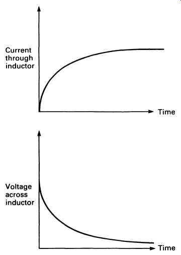
FIG. 15 graphs showing voltage and current in the circuit of FIG. 14.
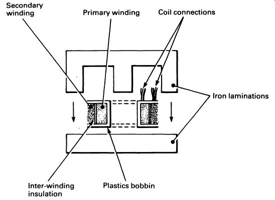
FIG. 16 a typical small transformer, showing the iron laminations.
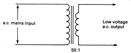
FIG. 17 circuit symbol for a transformer with a laminated core.
Transformers are rated according to the turns ratio, the power handling capability (in watts), and the type of application. Power transformers, intended for power supplies, usually have mains voltage primaries, and a high standard of insulation between the primary and secondary coils, for safety.
The secondary winding may have a range of connections, or taps, so the transformer can be used in different applications. It is important to realize that the transformer simply transforms voltages; there is no net power gain, always a small loss. If a transformer has a 200 V primary and a 1000 V secondary, the voltage will be increased by a factor of five times, but it will require more than five times the current in the primary than will be available from the secondary. You can trade current for voltage and vice versa, but the power will always be slightly less at the output, due to various losses in the transformer (dissipated, as usual, in the form of heat). Any component having a coil carrying current will have an inductive characteristic, though it may be swamped by other factors (resistance or capacitance). This may sometimes be important. For example, a relay is an electromagnetic switch, the coil being used to operate a mechanical switch. However, the coil has inductance. A relay operating from a 6 V supply can, when suddenly disconnected, produce an output pulse of 100 V or more as the current flowing through it drops very rapidly to zero. This voltage may be high enough to harm semiconductor components, and precautions should be taken to ensure that this 'spike' of high voltage is made harmless.
5. POWER SUPPLIES
I am going to introduce, prematurely, a semiconductor component that is described fully in Section 7. This is the diode, a sort of electronic one-way street that will let current pass through it in one direction but not in the other direction.
Diodes are used in power supply circuits, in association with transformers. A transformer is used to reduce the voltage of the a.c. mains to something more usable in electronic circuits, say 10 V in this case. however, the output is still a.c., and most electronic circuits require a direct current supply. The transformer's output can be converted, or rectified, by one or more diodes. FIG. 18 shows a transformer operating a circuit with a bulb. The waveform of the voltage across the bulb is shown also.
Now compare the waveform with the one in FIG. 19. The diode has blocked current flowing in one direction, so the top connection of the bulb is always positive. Only half the power reaches the bulb, so this is not a very efficient design. If four diodes are used, in a configuration called a bridge rectifier, the whole of the current available from the trans former can be passed through the bulb. Follow the current path through FIG. 20, first for one direction of output from the secondary, and then from the other.
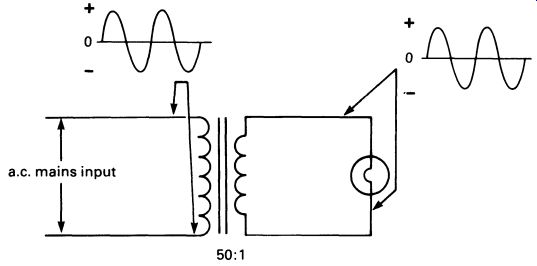
FIG. 18 waveforms at the input and output of a transformer driving
a lamp
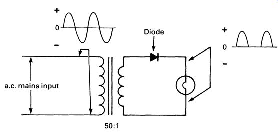
FIG. 19 waveforms for half-wave rectified direct current, supplied
by the secondary of the transformer, through a diode
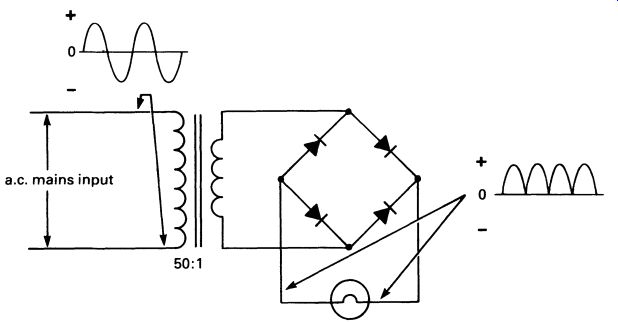
FIG. 20 the diode 'bridge rectifier' configuration, used to provide
full wave rectification of an a.c. supply (although both halves of the
a.c. input waveform pass through the lamp, the current flow through the
lamp is not smooth-and this would upset the operation of many circuits)
The supply to the bulb is now d.c., but constantly changing in voltage.
The voltage supplied to the bulb (or any other circuit) can be smoothed by means of a large-value capacitor connected in parallel with the load (the bulb in this case). The effect of the capacitor is to supply the required current when the voltage drops during each half -cycle of the mains supply.
When the voltage rises, the capacitor is recharged, so that it has energy available to fill in the 'gaps' in the supply. FIG. 21 illustrates this.
This circuit is the basis of almost all power supply systems used in electronic circuits. Although much more sophisticated 'regulated' power supplies are often used-as you will discover when you get to Section 20 the transformer, bridge rectifier and smoothing capacitor feature in all the designs.
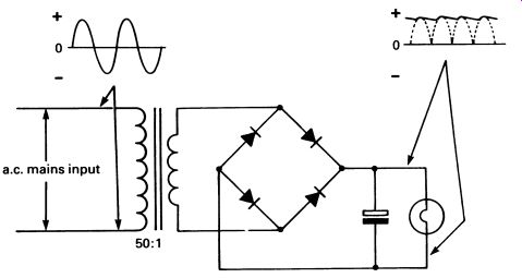
FIG. 21 the bridge rectifier with smoothing capacitor; a large capacitor
is used to provide power during the 'gaps' in the rectified waveform.
Before leaving the subject of diodes and circuits, I will use this opportunity to mention an important fact that electronics engineers, secretly, are a little ashamed of.
The current flowing through the power supply circuits above is flowing in the direction of the arrowhead of the diode symbol. The arrowhead to indicate current flow occurs over and over again in circuit diagrams.
Current, we say, always flows from positive to negative.
Actually, it doesn't.
Electrons move the other way, from negative to positive, opposite to what has been called 'conventional current'. This is an odd fact, but one that only rarely complicates circuit design and analysis. The reason for it, frankly, is a Mistake. When the study of electricity was in its infancy, there was a need to standardize (in books and notes) on the direction of current flow. In the absence of our knowledge of electrons and atoms, someone sat down to perform an experiment that would settle the problem of current flow once and for all. It might even have been Volta, or Faraday, I can't remember. The experiment consisted of setting up equipment that would make a very long electric spark, and then repeatedly watching the spark. Eventually the experimenter made up his mind that the spark always jumped from here to here. It was at this point that the Mistake was made.
When, years later, it was discovered that (i) electrons go from negative to positive, and (ii) electric sparks jump too fast to see which way they are going anyway, 'conventional current' was established in all the textbooks, and it would have been disastrous to have tried to change it.
So we still say that 'conventional current' flows from positive to negative, except when we are discussing semiconductor physics, where electron flow is what matters.
6. PRINTED CIRCUITS
Before leaving passive components, mention must be made of that most ubiquitous of passive components, the printed circuit board. It used to be necessary to build a chassis for every piece of electronic circuitry, with insulating strips carrying rows of tags for component connections. The printed circuit board (PCB), however, has made possible small, light weight circuits, easy to construct and repair.
The PCB consists of a strong plastic laminate or fiberglass laminate board, with a thin sheet of copper bonded to one (or sometimes both) side(s). The sheet is drilled with holes that enable the circuit components to be pushed into place with their connecting leads through the holes.
The underneath (copper) side of the PCB is made in a pattern which corresponds to the required wiring pattern. The components are soldered in place, and the PCB provides both support for the parts and the necessary electrical interconnections. A completed PCB can be seen in Figure 15.23 (p. 219). Appendix 1 shows some examples of PCB patterns.
In production, the PCB is produced using automatic processes. The required pattern is produced as a photographic negative, and this is printed on to the PCB, which has been coated on the copper side with a photo graphic emulsion. The PCB is then developed like a photograph, leaving emulsion only on the parts that were exposed to light.
Next, the PCB goes into a bath of a powerful chemical that will dissolve copper-ferric chloride is often used. The ferric chloride etches away all the copper, except where it is protected by the emulsion. The emulsion is cleaned off, leaving the copper pattern. Holes are drilled or punched as required, and the board is ready for assembly (although the copper is often coated with a thin layer of solder by a process known as roller tinning to improve ease of soldering.
Anyone can make PCBs. For single PCBs, the circuit is simply drawn on to the copper with an etch-resistant ink (special pens are available) or with rub-on transfers. The rest of the process is the same as that used commercially.
Be careful with the strong ferric chloride solution--it is corrosive, poisonous, and will gallop through most metals. Use rubber gloves, plastic dishes, plastic tongs, and don't work on a stainless steel drainer!
* * * * * * * * * * * * * * * * * * *
Electricity and Passive Components
Sections 2 and 3 have been intended as revision only. If you want to know more about electricity, there are many good textbooks available. If, however, you have found the first three sections of this guide fairly easy going, you will be able to understand the rest without too much trouble.
QUESTIONS
1. State the value and tolerance of the following resistor color codes, as read from the resistors in a circuit board in a radio receiver: brown, black, red, silver; brown, grey, yellow, silver; red, black, black, silver; gold, red, blue, green.
2. What is the largest commonly used unit of capacitance?
3. Three capacitors are connected in parallel. Their values are 4.7 uF, 10 uF and 3.3 uF. What is the combined capacitance? If the tolerance of each is +20 percent and -10 percent, what are the maximum and minimum values of capacitance to be expected for the combination?
4. The following two capacitors are connected in series: 3.3 nF, 2.2 nF. What is the combined capacitance?
5. A transformer is taking a current of 500mA from a 220V a.c. supply.
If the output of the transformer is at 440V, what is the maximum current the transformer could deliver from its secondary winding?