AMAZON multi-meters discounts AMAZON oscilloscope discounts
Thomas Alva Edison is chiefly known as the inventor of the phonograph, and as one of the inventors of the electric lamp. It is less well known that Edison nearly invented the thermionic diode-the 'breakthrough' device that heralded the beginning of the science of electronics.
In the early 1880s Edison was trying to improve his electric lamp. One of the problems he had was in preventing the inside of the glass envelope going black and obscuring the light. He realized that the filament of the lamp was evaporating, and wondered if he could use a wire grid to intercept the material before it got to the glass. The modified lamp was based on the design in FIG. 1.
Unfortunately it didn't work, but during his experiments Edison did try the effect of applying an electric voltage to the grid. He observed that if the grid were made negative with respect to the filament, nothing much happened, but if he made it positive with respect to the filament, he could draw a substantial current from it. This was mildly interesting but was not going to help him with the electric lamp, so he called it the ' Edison effect' and flied the idea for future development ...
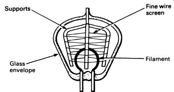
FIG. 1 Edison's modified lamp
It was left to John Ambrose Fleming, in 1904, to do the essential pioneering work in electronics, and the device which carries his name, the Fleming diode, bears tribute to his work.
1. THE THERMIONIC DIODE
The simplest form of Fleming diode is almost identical to Edison's modified lamp, and is illustrated in FIG. 2.
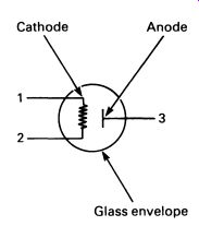
FIG. 2 a Fleming diode
The cathode is just like a lamp filament, though it is treated with thorium to increase the number of electrons that can be driven off when it is heated.
Facing the cathode is the anode, a metal plate connected to an outside terminal. The two parts are sealed inside a glass envelope in which there is a vacuum. It is easy to see how the Fleming diode, or thermionic diode, works.
When the cathode filament is heated by passing a current through terminals (1) and (2) in FIG. 2 electrons are driven off the filament.
These free electrons are separated from their parent atoms by the heat. If the anode is made negative compared with the cathode, the electrons are repelled by the anode (like repels like; remember that the electrons have negative charges) and no current can flow through the diode.
On the other hand, a positive charge on the anode will attract electrons given off by the cathode, and they will move through the vacuum inside the envelope; this movement of electrons constitutes an electric current.
FIG. 3 shows a demonstration circuit for the thermionic diode.
The single cell provides heating current for the cathode, but otherwise plays no part in the operation of the circuit. Consider the effect of an alternating voltage applied across A -B in FIG. 3. While A is positive with respect to B a current will flow through the load resistor, RL, but if B is more positive than A, no current will flow. FIG. 4 compares the applied voltage with current flowing through RL. This is the principle of rectification-turning a.c. into d.c. The original Fleming diode was developed into the modern rectifier valve, shown in FIG. 5.
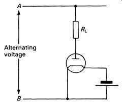
FIG. 3 demonstration circuit for a thermionic diode
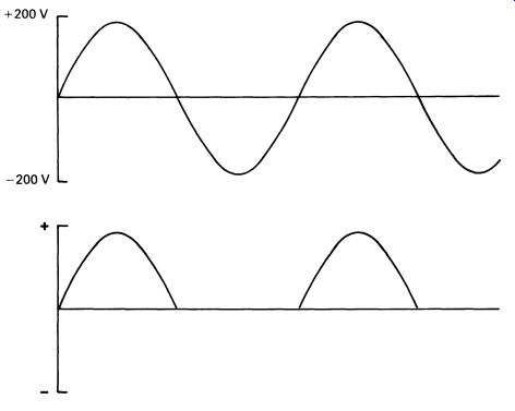
FIG. 4 rectification of an alternating voltage supply
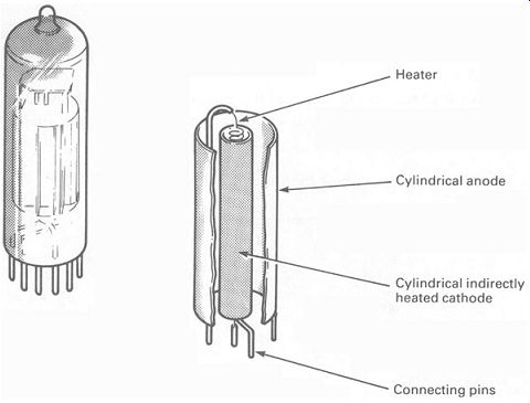
FIG. 5 construction of a modern thermionic diode valve
The major change is the fact that the cathode is indirectly heated. This separates the heating and electron-emitting functions. The heater filament is inside a narrow tube of thin metal, but nowhere does it come into con tact with the tube. The filament gets red hot, and this heats the tube (the cathode) which emits electrons. The main advantage is that the heater is electrically isolated from the cathode, and in a system involving several diodes (and other thermionic devices) the heaters can all be run from the same power supply, which can be a.c. for cheapness. The temperature of the heaters will fluctuate with the changing current of the supply, but that of the cathodes will remain relatively constant.
Another obvious (but important) development was the idea of putting all the connections at one end of the valve, so that it could be plugged into a base for easy replacement when the heater burned out.
Thermionic diodes like the one in FIG. 5 were in regular use in all types of equipment until the end of the 1960s, when they began to be superseded by solid-state diodes.
2. THE THERMIONIC TRIODE
The triode valve was invented by Lee De Forest in 1910. It is constructed like a Fleming diode but with an extra electrode, consisting of a grid of fire wires, interposed between the cathode and the anode. The basic layout is shown in FIG. 6, which, incidentally, is the circuit symbol for the triode valve.
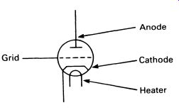
FIG. 6 circuit symbol for a thermionic triode
With the control grid unconnected, the triode behaves like a diode; but if the grid is held at a small negative potential relative to the cathode, the current flowing through the valve is reduced. It is easy to see why this is so; electrons travelling from the cathode to the anode are repelled by the charge on the grid and prevented from passing. Make the grid slightly more negative still, and the current that can flow from the anode ceases altogether.
For all practical purposes the grid takes no current at all, and the maximum voltage required on the grid to stop all current flow from the anode is substantially less than the anode voltage. Between certain limits (which depend on the valve construction and on the circuit in which it is used) the voltage at the anode of the valve is proportional to the grid voltage, but larger. Thus the valve can be used to amplify a signal applied to the grid, by increasing the amplitude (size) of the signal without changing its form.
FIG. 7 shows a triode valve in a simple amplifier circuit. The two resistors Rg and Rc are involved in keeping the grid at a more negative potential than the cathode. The output waveform as shown in the figure is the same shape as the input waveform, but has a larger voltage change it is amplified. A small voltage applied to the grid controls a much larger voltage. The principle of a small voltage or current controlling a larger voltage or current is one of the most fundamental concepts in electronics.
There are many types of valve apart from the triode. Almost all the designs are intended to improve the basic efficiency or to compensate for some undesirable characteristic. And almost all these improvements made the valve more complicated, and so more expensive. Valves are still used today--but not much. In all but a few specialist applications, the old 'vacuum-state' electronic devices have given way to solid-state equivalents.
There is only one really common thermionic device in use today. We will look at this next.
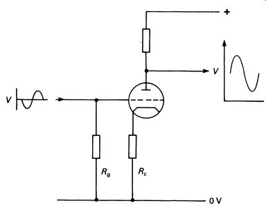
FIG. 7 a triode valve in a simple amplifier circuit (the heater connections
are not shown)
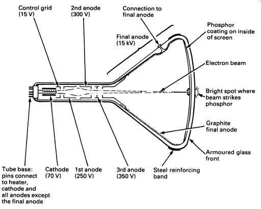
FIG. 8 cross-section through a cathode ray tube
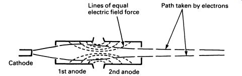
FIG. 9 the electric field between the first and second anodes concentrates
the beam of electrons, in much the same way that a lens concentrates
light.
3. THE CATHODE RAY TUBE
Most of us are familiar with the appearance of the cathode ray tube (CRT). More people spend more time looking at CRTs (the front, at least) than at anything else.
In the second half of this section, we can examine the inside of the TV tube-black-and-white version! FIG. 8 shows the basic design of the CRT. Compare it with the triode in FIG. 6, and you will see that it has more than a passing resemblance to a very large valve.
The cathode is indirectly heated, and is designed to emit electrons from a fairly small source. In front of the cathode is a control grid, in the form of a cylinder. In front of the control grid are two cylindrical anodes, care fully designed to act as a 'lens' when the proper voltages are applied. The object of these anodes (termed first and second anodes) is to concentrate the electrons into a beam, aimed at the front of the tube. FIG. 9 shows the way that the electric field produced by the two cylindrical anodes acts as an electron lens to concentrate the beam of electrons, just like a glass lens can be used to concentrate a beam of light.
Next there is a third anode (usually called the focus anode); voltage applied to this can be finely adjusted to bring the electron beam to a sharp focus on the screen. Lastly, there is a final anode, which is connected to a graphite coating applied to the inside of the flared part of the tube. All the flared part of the tube is thus at the same potential as that of the final anode-in fact the whole of the front part of the tube could be said to be the final anode, as it is all connected together.
The front part of the tube-the screen-is coated on the inside with a material called phosphor. This has the property of glowing brightly when struck by electrons (phosphors are also used on the inside of fluorescent lamps to make them glow). Phosphors can be made almost any color-a television tube would use one that glows white, while computer terminals often feature a green screen.
Operation of the tube is straightforward in principle. Electrons are emitted by the heated cathode, formed into a beam by the first two anodes, and focused by the third anode. The beam strikes the phosphor on the screen to produce a bright dot. The beam current, and thus the brightness of the dot, can be controlled by the voltage applied to the control grid.
A television tube is relatively long, so the electrons need a lot of energy to persuade them to travel down the tube. Moreover, they must have enough energy left to make the phosphor glow brightly when they reach the screen. For these reasons, the voltages associated with CRTs are high.
FIG. 8 indicates typical voltages; the voltage on the final anode is always very high. It is so high, in fact, that the final anode connections cannot be made to the pin connectors at the back of the tube; this would pose insurmountable insulation problems. Instead, the high voltage connection is made to a special plug on the side of the flared part of the tube.
A thick, heavily insulated wire to the final anode is a prominent feature of any TV receiver.
4. BEAM DEFLECTION
So far we have described a CRT that produces a single dot in the center of the screen. The brightness can be controlled by the grid, but we have to use some extra parts to move the dot around the screen. The most common method is to use magnetic deflection. Electrons are easily influenced by magnetic fields, so a suitably designed system of coils, slipped over the outside of the tube neck, can be used to bend the electron beam, causing the dot of light to move up and down and from side to side. Two separate sets of coils are used, for vertical and for horizontal deflection. Television receivers and computer terminals always use magnetic deflection, but the oscilloscope, for example, uses another form of beam deflection, electro static deflection.
The oscilloscope is a measuring instrument that displays electrical waveforms on a CRT. The screen is marked with a grid and time and voltage can be read off the screen. An accurate and linear method of beam deflection is needed-electrostatic deflection is the answer. The tube is fitted internally with parallel horizontal and vertical plates, mounted in front of the focus anode. A high voltage applied to opposite plates will deflect the electron beam, and the degree of deflection on the screen is proportional to the applied voltage: ideal for a measuring instrument.
FIG. 10 shows the relative proportions of a television picture tube with magnetic deflection and an oscilloscope CRT.
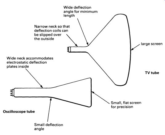
FIG. 10 Comparison of designs of cathode ray tubes--the upper one
shows a television tube, and the lower one an oscilloscope tube.
The wider deflection angle of the TV tube is designed to make the tube shorter for a given screen size. Design of the deflection coils and the circuits driving them is more difficult for wide-angle tubes, but the convenience (and better saleability) of shallow television receivers makes it worth the effort. The oscilloscope, on the other hand, is a piece of test equipment accuracy is the important factor, and the length of the instrument is unimportant.
COLOR television tubes work on the same principle, but are considerably complicated by the need to produce three independently controllable, perfectly superimposed pictures in red, green and blue! COLOR television picture tubes are given further explanation, along with TV systems, in Section 15.
QUESTIONS
1. Why does the cathode of a Fleming diode have to be heated?
2. In a television tube, electrons are fired at the front of the tube by an electron gun. What makes the front of the tube light up when the electrons strike it?
3. State the two different types of c 1eflection system used in a CRT.
4. What voltage would you find on the final anode of (i) a monochrome, (ii) a color TV tube? Is the voltage high enough to be dangerous?
5. What controls the beam current in a CRT? What effect does changing the beam current have on the screen?