Although the Internet is eroding their dominance, broadcast radio and television still play an important role in our lives. In some cases, they retain their supremacy. For example, adults spend about 1.5 hours in their cars every day, and of the time spent listening to audio content, 74% is broadcast radio and 6% is satellite radio.
Radio and television have historically been broadcast from terrestrial towers, transmitting on assigned frequencies to local markets. In addition, both services can be relayed nationwide by satellite. In addition, satellites are the workhorses of the global telecommunications industry.
This Section surveys audio broadcasting technology and some of its applications, with attention to digital audio radio (DAR) and digital television (DTV) broadcasting.
Satellite Communication
Outer space is only 62 miles away. If you could drive your car straight up, you could get there in about an hour.
However, since today's cars cannot do that, we need rockets instead, and it is enormously expensive to move things into space-perhaps $10,000 per pound. Despite the cost, we routinely launch space vehicles, and the most commercially valuable ones are communication satellites.
With satellite transmission, information is conveyed thousands of miles, to one receiver or to millions of receivers, using telecommunications satellites as unmanned orbiting relay stations.
Geostationary satellites use a unique orbit, rotating from west to east over the equator, moving synchronously with the earth's rotation. From the earth, they appear to be fixed in the sky; this is a geostationary orbit. Objects orbiting close to the earth rotate faster than the earth, and objects farther away rotate more slowly. The International Space Station (173 to 286 miles high) orbits the earth in 90 minutes. The moon (221,000 to 253,000 miles away) orbits in 27.3 days. At 22,236 miles above the earth, geostationary orbit (one orbit per day) is achieved; this is where geostationary satellites are parked. International law dictates a separation of 2 between vehicles. The unique properties of geostationary satellites make these positions quite valuable.
The conveyed signal has a line-of-sight characteristic similar to that of visible light; thus, it is highly directional.
From their high altitude, geostationary communications satellites have a direct line of sight to almost half the earth's surface; three satellites would encompass the entire globe except for small Polar regions. A satellite's footprint describes the area over which its receiving and transmitting antennas are focused. The footprint can cover an entire hemisphere, or a smaller region, with a gradual reduction in sensitivity away from the footprint's center area, as shown in FIG. 1. In this example, the footprint is characterized as effective isotropic radiated power (EIRP). Both earth stations (uplink and downlink) must lie within the satellite's footprint. Generally, C-band footprints cover larger geographical areas than Ku-band footprints. Because of the high orbit, a communications delay of 270 ms is incurred.

FIG. 1 Satellite downlink footprints are contoured to cover a specific
geographic location, and for example, minimize interference with neighboring
countries.
Satellite communications operate at microwave frequencies. Specifically, they occupy the super-high frequency (SHF) band extending from 3 GHz to 30 GHz; the broadcast spectrum is shown in FIG. 2. Two Fixed Satellite Services (FSS) bands are in common domestic use: the C-band (3.4 GHz to 7.075 GHz) and the Ku-band (10.7 GHz to 18.1 GHz). In either case, several higher frequency subbands (C-band: 5.725 GHz to 7.075 GHz;
Ku-band: 12.7 GHz to 18.1 GHz) are used for uplink signals, and several lower-frequency subbands (C-band: 3.4 GHz to 4.8 GHz; Ku-band: 10.7 GHz to 12.7 GHz) are used for downlink signals. Many geostationary satellites share the same spectral space, and ground stations must rely on physical satellite spacing and antenna directionality to differentiate between satellites.
Most C-band transponders use a 36-MHz bandwidth placed on 40-MHz centers, although in some cases 72 MHz transponders are used. Ku-band transponder bandwidths are either 36-MHz or 72-MHz wide. The C band affords superior propagation characteristics. However, Ku-band satellites can offset this with greater transponder antenna gain. Some satellites operate in both bands. Because the C-band must share its spectral space with other terrestrial applications, it suffers from the possibility of terrestrial microwave interference such as terrestrial microwave links. This necessitates a lower transmitting power and larger antenna diameter. C-band dishes are typically 2 meters in diameter or larger, and downlink stations must properly shield their antennas.
The shorter Ku-band wavelengths are more easily absorbed by moisture, thus the signal can be degraded by snow, rain, and fog. In particular, heavy rainfall might significantly degrade Ku-band signals. However, because the Ku-band is not shared with other terrestrial applications, it does not suffer from microwave interference, thus higher power can be applied. In addition, for a given size, Ku-band dishes provide higher gain than C-band dishes. Although Ku-band dishes are typically 1.8 meters in diameter, much smaller dishes are used in direct broadcast satellite applications. In some cases, a combination of bands is used. The Ku-band can be accessed via portable uplinks.
The downlinked signal is converted to the C-band at a ground station, and uplinked via the C-band for distribution.

FIG. 2 Satellite communications occupy the super high-frequency band,
with specific bands used for uplink and downlink transmissions. Only a few
of the uplink and downlink bands are shown.
Audio content can be transmitted as voice-grade 7.5 kHz audio, 15-kHz audio, or other formats. The voice-grade format is coded with continuously variable slope delta (CVSD) modulation to attain a data rate of 32 kbps. The 7.5-kHz format is sampled at 16 kHz, and the 15-kHz format is sampled at 32 kHz; both use 15-bit quantization followed by -law companding to yield 11 bits plus a parity bit. Multiple channels are multiplexed into a T-1 (1.544 Mbps) stream and sent to the uplink station. The individual audio channels are multiplexed into a 7.68-MHz bitstream, modulated to a 70-MHz intermediate frequency (IF) carrier, upconverted and uplinked for satellite distribution. A single 15-kHz PCM channel requires a bit rate of 512 kbps; companding decreases this to 384 kbps; data reduction decreases this to 128 kbps.
A satellite's transponders receive the ground station's uplink signal and retransmit it back to earth where a downlink receives the signal. A communications satellite might have 48 or more transponders each capable of receiving multiple ( 8 to 12) data channels from an uplink, or transmitting those channels to a receiving downlink.
Horizontally, vertically, and circularly polarized signals are broadcast to increase capacity in a frequency band.
Depending on the transmitting power of the satellite, the signal can be received by equipment of greater or lesser sophistication. For example, a 20-W satellite transmitter would require a receiving dish several meters in diameter, and a 200-W transmitter would require a dish diameter of less than a meter. The transponder reliability rate exceeds 99% over years of service.
Satellites use solar cells to derive power from solar energy. So that correct attitude stabilization is maintained (the antennas must stay pointed at the earth) geostationary satellites must rotate once every 24 hours as they circle the earth. This action is provided by thrusters that create spin when the satellite is first orbited. In addition, in the case of cube-shaped, body-stabilized 3D satellites, three internal gyroscopes control position about three axes, providing correction when necessary. In this design, solar cells are mounted on large solar sails, and motors move the sails to face the sun. Cylindrically shaped satellites, called spinners, achieve stabilization by spinning the entire satellite body about an axis. In this design, solar cells are mounted directly on the satellite's body; antennas must be despun. Hydrazine fuel thrusters are used to maintain absolute position within a 40-mile square in the geostationary orbit, compensating for the pull of the sun and moon. Most satellite failures are due to fuel depletion, and the resulting drifting of the vehicle due to space mechanics. A satellite might measure 20 feet in height and weigh 15,000 pounds at launch. A satellite's weight determines its launch cost. Because of limited satellite life span of 15 years or less, any satellite system must budget for periodic renewal of its spacecraft.
Interestingly, twice each year all geostationary satellite downlink terminals undergo solar outages (for 5 minutes or so) when the sun, the relaying satellite, and the earth station are all in a straight line. The outage occurs when the shadow of the antenna's feed element is in the center of the dish; solar interference (noise power from the sun) degrades reception. Solar transit outages occur in the spring and fall. Beginning in late February, outages occur at the U.S.-Canada border and slowly move southward at 3 latitude per day, and beginning in early October outages begin at the U.S.-Mexico border and move northward at the same rate. In addition, eclipses of geostationary satellites occur about 90 evenings a year in the spring and fall when the earth blocks the sun's light to the satellite.
Onboard batteries provide continuous power while the solar sails go dead for 70 minutes.
Instead of using a relatively few geostationary satellites, low earth orbit (LEO) satellite systems use a constellation of many satellites to permit low-cost access. Rather than sitting in fixed points, LEOs ride in low and fast orbits, moving freely overhead in the sky. With LEOs, a terrestrially transmitted signal is picked up by a satellite passing overhead, and it relays a signal as directed. Because of their close proximity, LEOs minimize communication latency (perhaps 100 ms or less). Because they are small, they can be launched more cheaply, and are more easily replaced. Because the system is distributed, any single satellite failure will have a minimal impact on overall operation. Some LEOs operate at a frequency of less than 1 GHz; they have relatively small bandwidths and are used for low bit-rate applications such as paging. Other LEOs operate anywhere from 1 GHz to 30 GHz.
Medium earth orbit (MEO) satellites use special orbital mechanics for more efficient landmass coverage. Because of its higher altitude, an MEO satellite's coverage footprint is much larger than that of a LEO; this reduces the number of deployed satellites. Instead of using circular orbits, MEO satellites might use elliptical orbits; for example, with apogees of 4000 miles and perigees of 300 miles. The apogees are near the northern extremity of the orbits, thus the satellites spend more time over domestically populated areas. Moreover, the orbits can be configured to be sun synchronous; their orbital plane remains fixed relative to the sun throughout the year. In this way, the satellite's greatest orbital coverage can be optimized to the time of day with peak usage.
Direct Broadcast Satellites
In many applications, satellites are used to convey programs from one point to a few others. For example, a television channel provider can beam programming to local cable companies across the country, which in turn convey the programs to subscribers via coaxial cable. Direct broadcast satellite (DBS) is a point-to-multipoint system in which individual households equipped with a small parabolic antenna and tuner receive broadcasts directly from a geostationary satellite. The satellite receives digital audio and video transmissions from ground stations and relays them directly to individuals. The receiving system comprises an offset parabolic antenna that collects the microwave signals sent by the satellite, and a converter mounted at the antenna's focal point that converts the microwave signal to a lower frequency signal. Because of the high sensitivity of these devices and relatively high satellite transmitting power, the parabolic antenna can be 0.5 meter in diameter. The dishes are mounted outside the home with a southern exposure and are manually aligned with a diagnostic display showing received signal strength.
Inside the home, a phase-locked loop tuner demodulates the signal from the converter into video and audio signals suitable for a home television or stereo. For areas not centrally located in the satellite's footprint, larger antennas of a meter or more in diameter can be used for favorable reception. Direct broadcast satellite systems transmit in the Ku-band, a higher frequency region than the very high frequency (VHF) and ultra high frequency (UHF) channels used for terrestrial television broadcasting. Bandwidth is 27 MHz per channel.
The DirecTV system is an example of a direct broadcast satellite system providing digital audio and video programming to consumers. Subscribers use a 0.5-meter diameter satellite dish and receiver to receive over 200 channels of programming. Three co-located, body stabilized HS 601 satellites orbit at 101 west longitude, each providing 16 high-power (120 W) transponders in the Ku-band (uplink: 17.2 GHz to 17.7 GHz; downlink: 12.2 GHz to 12.7 GHz). They beam their high-power signals over the continental United States, lower Canada, and upper Mexico. Signals originate from a broadcast center and are digitally delivered over the satellite link, then converted into conventional analog signals in the home, providing audio and video output. MPEG-2 coding is used to reduce a channel's nominal bit rate from 270 Mbps to a rate of 3.75 Mbps to 7.5 Mbps. The compressed data is time-division multiplexed. The bit rate of individual channels can be continuously varied according to content or channel format.
The signal chain also includes Reed-Solomon and convolutional error correction coding, and quadrature phase-shift keying (QPSK) modulation. The advent of low cost satellite-based distribution technology has changed the way that radio and television signals are received.
Digital Audio Radio
Analog broadcasting harkens back to the early days of audio technology. However, in August 1986, WGBH-FM in Boston simulcast its programming over sister station WGBX-TV using a pseudo-video PCM (F1) processor, coding the stereo digital audio signal as a television signal, thus experimentally delivering the first digital audio broadcast. Following this experiment, the broadcasting industry has developed digital audio radio (DAR) technologies, also known as digital audio broadcasting (DAB). Instead of using analog modulation methods such as AM or FM, DAR transmits audio signals digitally. DAR is designed to replace analog AM and FM broadcasting, providing a signal that is more robust against reception problems such as multipath interference. In addition to audio data, a DAR system supports auxiliary data transmission; for example, text, graphics, or still video images ("radio with pictures") can be conveyed.
The evolution of a DAR standard is complicated because broadcasting is regulated by governments and swayed by corporate concerns. Two principal DAR technologies have been developed: Eureka 147 DAB and in-band on-channel (IBOC) broadcasting known as HD Radio. The way to DAR has been labyrinthine, with each country choosing one method or another; there are no worldwide standards.
Digital Audio Transmission
Radio signals are broadcast as an analog or digital baseband signal that modulates a high-frequency carrier signal to convey information. For example, an AM radio station might broadcast a 980-kHz carrier frequency, which is amplitude modulated by baseband audio information.
The receiver is tuned to the carrier frequency and demodulates it to output the original baseband signal; IF modulation techniques are used. Digital transmissions use a digital baseband signal, often in a data reduction format.
The digital data modulates a carrier signal (a high frequency sinusoid) by digitally manipulating a property of the carrier (such as amplitude, frequency, or phase); the modulated carrier signal is then transmitted. In addition, prior to modulation, multiple baseband signals can be multiplexed to form a digital composite baseband signal.
An example of a transmit/receive signal chain is shown in FIG. 3.
In any digital audio broadcasting system, it is important to distinguish between the source coder and the channel coder. The source coder performs data reduction coding so the wideband signal can be efficiently carried over reduced spectral space. The channel coder prepares the rate-reduced signal for modulation onto radio frequency (RF) carriers, the actual broadcasting medium; this is needed for efficient, robust transmission. One important consideration of channel coding is its diversity to reduce multipath interference that causes flat or frequency selective interference, called a fade, in the received signal.
Channel coders can use frequency diversity in which the source coder data is encoded on several carrier frequencies spread across a spectral band; a fade will not affect all of the received carriers.
Using adaptive equalization, the receiver might use a training sequence placed at the head of each transmitted data block to recognize multipath interference and adjust its receiver sensitivity across the channel spectrum to minimize interference. In addition, because multipath interference can change over time (particularly in a mobile receiver), time diversity transmits redundant data over a time interval to help ensure proper reception; a cancellation at one moment might not exist a moment later. With space diversity, two or more antennas are used at the receiver (for example, on the windshield and rear bumper of a car), so the receiver can choose the stronger received signal. A fade at one spectral point at one antenna might not be present at the other antenna. Finally, in some systems, space diversity can be used in the transmission chain; multiple transmission antennas are used and the receiver selects the stronger signal.
Digital audio radio can be broadcast in a variety of ways. Like analog radio, DAR can be transmitted from transmission towers, but DAR is much more efficient. An analog radio station might broadcast with 100,000 W of power. However, a DAR station might require only 1000 W, providing a significant savings in energy costs. Terrestrial transmission continues the tradition of locally originated stations in which independent stations provide local programming. To their advantage, terrestrial DAR systems can be implemented rather quickly, at a low overall cost.

FIG. 3 An example of signal processing in a transmit/receive signal path.
DAR can also be broadcast directly from satellites, using a system in which programs are uplinked to satellites then downlinked directly to consumers equipped with digital radios. Receivers use low-gain, nondirectional antennas, for example, allowing automotive installation as small flush mounted modules on the car roof. The resulting national radio broadcasting networks particularly benefit rural areas; they are ideal for long-distance motorists, and a satellite system could extend the effective range of terrestrial stations.
In some proposed satellite radio systems, the transmitting satellite would have multiple (perhaps 28) spot beams, each aimed at a major metropolitan area, as well as a national beam. In this way, both regional and national programming could be accommodated. For example, each beam could convey 16 separate stereo audio programs; listeners in a metropolitan area would receive 32 channels (16 local and 16 national). The use of spot beams was pioneered by the National Aeronautics and Space Administration (NASA); the TDRS (Tracking Data and Relay System) geostationary satellites use space-to-earth spot beam transponders. Although TDRS is used to track low-orbit spacecraft (replacing the ground-tracking stations previously used), it approximates operation of a direct radio broadcast system. NASA and the Voice of America demonstrated a direct broadcast system in the S-band (at 2050 MHz) using MPEG-1 Layer I I coding to deliver a 20 kHz stereo signal at a rate of 256 kbps. The experimental receiver used a short whip antenna, with reasonable indoor performance. The geostationary satellite used a 7-W transmitter.
Implementation of any commercial satellite system requires great capital investment in the satellite infrastructure. In addition, to ensure good signal strength in difficult reception areas such as urban canyons and tunnels, local supplemental transmitters known as gap fillers are needed. Using a system known as single-frequency networking, these transmitters broadcast the same information and operate on the same frequency with contiguous coverage zones. The receiver automatically selects the stronger signal without interference from overlapping zones.
Alternatively, digital audio programs can be broadcast over home cable systems. For example, digital audio programming originating from a broadcast center can be delivered via satellite to local cable providers. Time division multiplexing is used to efficiently combine many digital audio channels into one wideband signal. At the cable head-end, the channels are demultiplexed, encrypted, and remodulated for distribution to cable subscribers over an unused television channel. At the consumer's home, a tuner is used to select a channel, the channel is decoded, decrypted, and converted to analog form for playback. In practice, a combination of all three systems, terrestrial, satellite, and cable, is used to convey digital audio (and video) signals. FIG. 4 shows an example of transmission routing originating from an event such as a football game conveyed over various paths to consumers.
Spectral Space
A significant complication for any DAR broadcast system is where to locate the DAR band (perhaps 100 MHz wide) in the electromagnetic spectrum. Spectral space is a limited resource that has been substantially allocated.
Furthermore, the frequency of the DAR transmission band will impact the technology's quality, cost, and worldwide compatibility. Any band from 100 MHz to 1700 MHz could be used for terrestrial DAR, but the spectrum is already crowded with applications. In general, lower bands are preferable (because RF attenuation increases with frequency) but are hard to obtain. The S-band (2310 MHz to 2360 MHz) is not suitable for terrestrial DAR because it is prone to interference. However, the S-band is suitable for satellite delivery. Portions of the VHF and UHF bands are allocated to DTV applications.
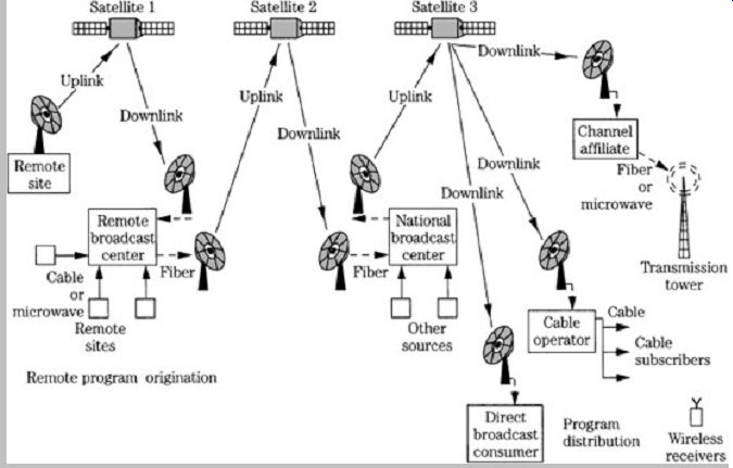
FIG. 4 An example of transmission routing used to convey audio and video
signals.
A worldwide allocation would assist manufacturers, and would ultimately lower cost, but such a consensus is impossible to obtain. The World Administrative Radio Conference (WARC) allocated 40 MHz at 1500 MHz (L band) for digital audio broadcasting via satellite, but ultimately deferred selection for regional solution. Similarly, the International Radio Consultative Committee (CCIR) proposed a worldwide 60-MHz band at 1500 MHz for both terrestrial and satellite DAR. However, terrestrial broadcasting at 1500 MHz is prone to absorption and obstruction, and satellite broadcasting requires repeaters.
There is no realistic possibility of a worldwide satellite standard. In the United States, in 1995, the Federal Communications Commission (FCC) allocated the S-band (2310 MHz to 2360 MHz) spectrum to establish satellite delivered digital audio broadcasting services. Canada and Mexico have allocated space at 1500 MHz. In Europe, both 1500-MHz and 2600-MHz regions have been developed.
Ideally, whether using adjacent or separated bands, DAR would permit compatibility between terrestrial and satellite channels. In practice, there is not a mutually ideal band space, and any allocation will involve compromises.
Alternatively, new DAR systems can cohabit spectral space with existing applications. Specifically, the DAR system uses a shared-spectrum technique to locate the digital signal in the FM and AM bands. By using an in-band approach, power multiplexing can provide compatibility with analog transmissions, with the digital broadcast signal coexisting with the analog carriers. Because of its greater efficiency, the DAR signal transmits at lower power relative to the analog station. An analog receiver rejects the weaker digital signal as noise, but DAR receivers can receive both DAR and analog broadcasts. No matter how DAR is implemented, the eventual disposition of AM and FM broadcasting is a concern. A transition period will be required, lasting until analog AM and FM broadcasts gradually disappear. HD Radio is an example of an in-band system; it is described later.
Data Reduction
Digital audio signals cannot be practically transmitted in a PCM format because the bandwidth requirements would be extreme. A stereo DAB signal might occupy 2 MHz of bandwidth, compared to the approximately 240 kHz required by an analog FM broadcast. Thus, DAR must use data reduction to reduce the spectral requirement. For example, instead of a digital signal transmitted at a 2-Mbps rate, a data-reduced signal might be transmitted at 256 kbps. There are numerous perceptual coding methods suitable for broadcasting. For example, the MPEG algorithms use subband and transform coding with numerous data rates such as 256, 128, 96, 64, and 32 kbps. Although data reduction is used successfully in many applications, the bandwidth limitations of commercial radio applications, the bandwidth limitations of commercial radio broadcasting make it a particularly challenging application.
In addition, an audio signal passing through a broadcast chain may undergo multiple data reduction encoding/decoding stages; this increases distortion and artifacts. Data reduction via perceptual coding is discussed in Sections 10 and 11.
Technical Considerations
The performance of a digital audio broadcasting system can be evaluated with a number of criteria including: delivered sound quality, coverage range for reliable reception, interference between analog and digital signals at the same or adjacent frequencies, signal loss in mountains or tunnels, deep "stoplight" fades, signal "flutter" produced by passing aircraft, data errors in the presence of man-made and atmospheric noise, interference from power lines and overhead signs, attenuation by buildings, multipath distortion during fixed and mobile reception, receiver complexity, and capacity for auxiliary data services. In addition, ideally, the same receiver can be used for both terrestrial and satellite reception.
Designers of DAR systems must balance many variables to produce a system with low error rate, moderate transmitted power levels, and sufficient data rate, all within the smallest possible bandwidth. As with any digital data system, a broadcasting system must minimize errors. The bit-error rate (BER) must be reduced through error correction data accompanying the audio data, and is monitored for a given carrier-to-noise ratio (C/N) of the received signal. Transmitted digital signals are received successfully with low C/N, but analog signals are not.
Generally, a BER of 10^-4 at the receiver might be nominal, but rates of 10^-3 and 10^-2 can be expected to occur, in addition to burst errors.
Receiver performance also can be gauged by measuring the ratio between the energy per bit received to the power spectral density of the input noise in a 1-Hz bandwidth; this is notated as Eb/No. Designers strive to achieve a low BER for a given C/N or Eb/No. Digital transmission tends to have brick-wall coverage; the system operates well with a low BER within a certain range, then BER increases dramatically (yielding total system failure) when there is an additional small decrease in signal strength.
Most digital communications systems use pulse-shaping techniques prior to modulation to limit bandwidth requirements. Pulse shaping performs lowpass filtering to reduce high-frequency content of the data signal. Because this spreads the bit width, resulting in intersymbol interference, raised cosine filters are used so that the interference from each bit is nulled at the center of other bit intervals, eliminating interference.
Multipath interference occurs when a direct signal and one or more strongly reflected and delayed signals, for example, signals reflected from a building, destructively combine at the receiver. The delay might be on the order of 5 s. In addition, other weak reflected signals might persist for up to 20 s. The result at the receiver is a comb filter with 10-dB to 50-dB dips in signal strength, as shown in Fig. 5. This type of RF multipath is a frequency-selective problem, and short wavelengths, for example, in FM broadcasting, are more vulnerable. When the receiver is moving, multipath interference results in the amplitude modulation "picket fence" effect familiar to mobile analog FM listeners. Even worse, in a stoplight fade, when the receiver is stopped in a signal null, the signal is continuously degraded; a single, strong specular reflection completely cancels the transmitted signal's bandwidth. FM signals can become noisy, but because digital signals operate with a small C/N ratio, they can be lost altogether.
Increasing power is not a remedy because both the direct and reflected signal will increase proportionally, preserving the interference nulls.

FIG. 5 Multipath interference degrades signal quality at the receiver.
A. A radio receives the direct transmission path, as well as delayed single
and multiple reflection paths. B. The combined path lengths produce nulls in
signal strength in the received channel bandwidth.
Another effect of multipath interference, caused by short delays, occurs in the demodulated bitstream. This is delay spread in which multiple reflections arrive at the receiver over a time interval of perhaps 15 s. The result is intersymbol interference in the received data; bits arrive at multiple times. This can be overcome with bit periods longer than the spread time. However, with conventional modulation, this would limit the bit rate to less than 100 kbps; thus, data reduction must also be used. Frequency diversity techniques are very good at combating multipath interference. By placing the data signal on multiple carriers, interference on one carrier frequency can be overcome.
Two types of multiplexing are used. The most common method is time-division multiplexing (TDM), in which multiple channels share a single carrier by time interleaving their data streams on a bit or word basis; different bit rates can be time-multiplexed. Frequency-division multiplexing (FDM) divides a band into subbands, and individual channels modulate individual carriers within the available bandwidth. A single channel can be frequency-multiplexed;
this lowers the bit rate on each carrier, and lowers bit errors as well. Because different carriers are used, multipath interference is reduced because only one carrier frequency is affected. On the other hand, more spectral space is needed.
Phase-shift keying (PSK) modulation methods are commonly used because they yield the lowest BER for a given signal strength. In binary phase-shift keying (BPSK), two phase shifts represent two binary states. For example, a binary 0 places the carrier in phase, and a binary 1 places it 180 out of phase, as shown in FIG. 6A. This phase change codes the binary signal, as shown in Fig. 6B. The symbol rate equals the data rate. In quadrature phase-shift keying (QPSK), four phase shifts are used.
Thus, two bits per symbol are represented. For example, 11 places the carrier at 0, 10 at 90, 00 at 180, and 01 at 270, as shown in FIG. 6C. The symbol rate is twice the transmission rate. QPSK is the most widely used method, especially for data rates above 100 Mbps. Higher-order PSK can be used (for example, 8-PSK, 16-PSK) but as the number of phases increases, higher Eb/No is required to achieve satisfactory BER. Other modulation methods include amplitude shift-keying (ASK) in which different carrier powers represent binary values, frequency shift keying (FSK) in which the carrier frequency is varied (FSK is used in modems), and quadrature amplitude modulation (QAM) in which both the amplitude and phase are varied.
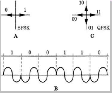
FIG. 6 Phase-shift keying (PSK) is used to modulate a carrier, improving
efficiency. A. Phasor diagram of binary phase-shift keying (BPSK). B. An example
of a BPSK waveform. C. Phasor diagram of quadrature phase-shift keying (QPSK).
The bandwidth (BW) for an M-PSK signal is given by:

where D is the data rate in bits per second. For example, a QPSK signal transmitting a 400-kbps signal would require a bandwidth of between 200 kHz to 400 kHz. A 16-PSK signal could transmit the same data rate in half the bandwidth, but would require 8 dB more power (Eb/No) for a satisfactory BER. Given the inherently high bandwidth of digital audio signals, data reduction is mandatory to conserve spectral space, and provide low BER for a reasonable transmission power level. As Kenneth Springer has noted, a 4,000,000-level PSK modulation would be needed to make a transmitted signal's bandwidth equal its original analog baseband; the required power would be prohibitive. But with a 4:1 data reduction, 256-PSK provides the same baseband. In practice, an error-corrected, data-reduced signal, with QPSK modulation, can be transmitted with lower power than an analog signal.
One of the great strengths of a digital system is its transmission power efficiency. This can be seen by relating coverage area to the C/N ratio at the receiver. A digital system might need a C/N of only 6 dB, but an FM receiver needs a C/N of 30 dB, a difference of 24 dB, to provide the same coverage area. The field strength for a DAR system can be estimated from:

where E minimum acceptable field strength at the receiver in dBu and Vi thermal noise of receiver into 300 in dBu where:

where k=1.38 10^-23 W/kHz
T temperature in Kelvin (290 K at room temperature)
R input impedance of the receiver
B bandwidth of the digital signal
NF noise figure of the receiver
C/N carrier-to-noise ratio for a given BER
F_MHz transmission frequency
For example, if a DAR signal is broadcast at 100 MHz, with 200-kHz bandwidth, into a receiver with 6-dB noise figure, with C/N of 6 dB, then E 5.5 dBu. In contrast, an FM receiver might require a field strength of 60 dBu for good reception, and about 30 dBu for noisy reception.
Eureka 147 Wideband Digital Radio
The Eureka 147 digital audio broadcasting (DAB) system was selected as the European standard in 1995 for broadcasting to mobile, portable, and fixed receivers. The Eureka 147 technology is suitable for use in terrestrial, satellite hybrid (satellite and terrestrial), and cable applications. Canada, Australia, and parts of Asia and Africa have also adopted the Eureka 147 system for the broadcast of DAB signals. Eureka is a research and development consortium of European governments, corporations, and universities, established in 1985 to develop new technologies, through hundreds of projects ranging from biotechnology to transportation. Project number 147, begun in 1986, aimed to develop a wideband digital audio broadcasting system (formally known as DAB, as opposed to DAR). A prototype Eureka 147/DAB system was first demonstrated in a moving vehicle in Geneva in September 1988 and many improvements followed. System specifications were finalized at the end of 1994.
In traditional radio broadcasting, a single carrier frequency is used to transmit a monaural or stereo audio program, with one carrier per radio station. This method allows complete independence of stations, but poses a number of problems. For example, reception conditions at the receiver might produce multipath interference at the desired carrier frequency, in part because the station's bandwidth is narrow (e.g., approximately 240 kHz for analog FM radio). In addition, wide guard bands must be placed around each carrier to prevent adjacent interference. In short, independent carrier transmission methods are not particularly robust, and are relatively inefficient from a spectral standpoint. Eureka 147 employs a different method of transmission coding which overcomes many problems incurred by traditional broadcast methods.
Eureka 147 digitally combines multiple audio channels, and the combined signal is interleaved in both frequency and time across a wide broadcast band. A receiver does not tune to a single carrier frequency. Rather, it performs partial fast Fourier transforms (FFTs) on a broadcast band and decodes the appropriate channel data from among many carriers. This innovative approach provides spectrum- and power-efficient transmission and reliable reception even over a multipath fading channel. A block diagram of a Eureka 147 transmitter is shown in Fig. 7A. Audio data as well as other data is individually encoded with channel coders and interleaved. A multiplexer combines many different services to create a main service channel (MSC). The multiplexer output is frequency interleaved and synchronization symbols are added.
Channel coding is applied: coded orthogonal frequency division multiplexing (COFDM) with QPSK modulation is employed for each carrier to create an ensemble DAB signal. In orthogonal coding, carriers are placed at 90 phase angles such that the carriers are mutually orthogonal and the demodulator for one carrier is not affected by the modulation of other carriers.

FIG. 7 Block diagrams of the Eureka 147/DAB system. A. DAB transmitter.
B. DAB receiver.
COFDM processing divides the transmitted information into many bitstreams, each with a low bit rate, which modulate individual orthogonal carriers so that the symbol duration is longer than the delay spread of the transmission channels. The carriers in this ensemble signal may be generated by an FFT. Depending on the transmission mode employed, there may be 1536, 384, or 192 carriers.
In the presence of multipath interference, some of the carriers undergo destructive interference while others undergo constructive interference. Because of frequency interleaving among the carriers, successive samples from the same service are not affected by a selective fade, even in a fixed receiver. Time interleaving further assists reception, particularly in mobile receivers.
Carrier frequency centers are separated by the inverse of the time interval between bits, and separately modulated within their fractional spectral space, with a portion of the overall signal. This reduces the data rate on any one carrier, which promotes long bit periods. This frequency diversity yields immunity to intersymbol interference and multipath interference. To increase robustness over that provided by frequency diversity, and further minimize the effect of intersymbol and inter-carrier multipath interference, a guard interval is used; each modulation symbol is transmitted for a period that is longer than an actively modulated symbol period. During the interval, the phase of the carrier is unmodulated. This reduces the capacity of the channel but protects against reflection delays less than the duration of the guard interval. For example, a guard interval of 1/4 the active period protects against delays of 200 s.
The guard interval also decreases the burden placed on error correction. Convolutional coding adds redundancy, using, for example, a code with a constraint length of 7.
A collection of error-correction profiles is used, optimized for the error characteristics of MPEG Layer I I encoded data. The coders aim to provide graceful degradation as opposed to brick-wall failure. Thus, stronger protection is given to data for which an error would yield catastrophic muting, and weaker protection where errors would be less audible. Specifically, three levels of protection are used within an MPEG frame: the frame header and bit allocation data are given the strongest protection, followed by the scale factors, and subband audio samples, respectively. For example, errors in scale factor data may lead to improperly raised subband levels, whereas errors in a subband audio sample will be confined to a sample in one subband, and will likely be masked.
A block diagram of a Eureka 147 receiver is shown in FIG. 7B. The DAB receiver uses an analog tuner to select the desired DAB ensemble; it also performs down conversion and filtering. The signal is quadrature- demodulated and converted into digital form. FFT and differential demodulation is performed, followed by time and frequency de-interleaving and error correction. Final audio decoding completes the signal chain. Interestingly, a receiver may be designed to simultaneously recover more than one service component from an ensemble signal.
The DAB standard defines three transmission mode options, allowing a range of transmitting frequencies up to 3 GHz. Mode I with a frame duration of 96 ms, 1536 carriers, and a nominal frequency range of less than 375 MHz, is suited for a terrestrial VHF network because it allows the greatest transmitter separations. Mode II with a frame duration of 24 ms, 384 carriers, and a nominal frequency range of less than 1.5 GHz, is suited for UHF and local radio applications. Mode III with a frame duration of 24 ms (as in Mode II ), 192 carriers, and a nominal frequency range of less than 3 GHz, is suited for cable, satellite, and hybrid (terrestrial gap filler) applications. In all modes, the transmitted signal uses a frame structure with a fixed sequence of symbols. The gross capacity of the main service channel is about 2.3 Mbps within a 1.54-MHz bandwidth DAB signal. The net bit rate ranges from approximately 0.6 Mbps to 1.7 Mbps depending on the error correction redundancy used.
The Eureka 147 system's frequency diversity provides spectral efficiency that exceeds that of analog FM broadcasting. In addition, time interleaving combats fading experienced in mobile reception. The transmission power efficiency, as with many digital radio systems, is impressive; it can be 10 to 100 times more power-efficient than FM broadcasting; a Eureka 147 station could cover a broadcast market with a transmitter power of less than 1000 W. A principal feature of Eureka 147 is its ability to support both terrestrial and satellite delivery on the same frequency; the same receiver can be used to receive a program from either source. Eureka 147 uses MPEG-1 Layer II bit rate reduction in its source coding to minimize the spectrum requirements. Bit rate may range from 32 kbps to 384 kbps in 14 steps; nominally, a rate of 128 kbps/channel is used. Stereo or surround-sound signals could be conveyed. Nominally, a sampling frequency of 48 kHz is used; however, a 24-kHz sampling rate is optional. MPEG is discussed in Section 11.
One prototype Eureka 147 system, using L-band transmission, was evaluated in Canada. The COFDM used the following parameters: 7-MHz RF bandwidth, 448 quadrature phase-shift keying, subcarriers with 15.625-kHz spacing, 80-s symbol length with a 16-s guard interval, capacity to transmit in multiplex 33 monophonic channels (129 kbps) or 16 stereo pairs, and 1 data channel. A transmitter with power of 150 W (1.5 kW ERP) total, or 9.4 W (94 W ERP) per stereo channel, produced a coverage range of 50 km, where ERP is effective radiated power.
The propagation and reception were similar to that of FM and UHF broadcasting; a local FM station required 40 kW ERP for 70-km coverage. Multipath errors were generally absent.
In another Canadian test, fixed and mobile receivers performed signal strength measurements using a 50-W transmitter and 16-dB antenna to broadcast nine CD quality channels (with the power of 200 W/channel) with reliable coverage up to distances of 45 km from the transmitter. In addition, Canadian tests verified the system's ability to provide a single-frequency network in which multiple transmitters can operate on a single frequency, without interference in overlapping areas. The Canadian system also proposed a mixed mode of broadcasting in which a single receiver could receive either satellite or terrestrial digital audio broadcasts. In a test in London, a Eureka 147 transmitter with 100 W of power provided coverage over 95% of the London area, with antennas similar to those used in table radios.
Eureka 147 is inherently a wideband system, and it can operate at any frequency range up to 3 GHz for mobile reception and higher frequencies for fixed reception.
Practical implementation requires a spectrum allocation outside the existing commercial broadcast bands. The narrowest Eureka 147 configuration uses 1.5 MHz to transmit six stereo channels. In practice, a much wider band would be required for most applications. A fully implemented Eureka 147 might occupy an entire radio band. Because spectral space is scarce, this poses a problem. In general, Eureka 147 can operate in a number of bands, ranging from 30 MHz to 3 GHz; however, a 100 MHz to 1700-MHz range is preferred. Domestic proponents argued for allocation of the L-band (1500 MHz) for Eureka 147, but the U.S. government, for example, was unwilling to commit that space; in particular, the U.S. military uses that spectral space for aircraft telemetry.
Another proposal called for operation in the S-band (2300 MHz). Although the FCC authorized the use of the S-band for digital satellite radio, lack of suitable spectral space posed an insurmountable obstacle in the development of a Eureka 147 system in the United States.
Other drawbacks exist. In particular, the need to combine stations leads to practical problems in some implementations. Eureka 147's designers, taking a European community bias, envisioned a satellite delivery system that would blanket Europe with a single footprint.
Terrestrial transmitters operating on the same frequencies would be used mainly as gap fillers, operating on the same frequency. This monolithic approach is opposed in the United States where independent local programming is preferred. With satellite delivery of Eureka 147, the concept of local markets becomes more difficult to implement, while national stations become easier to implement. This would redefine the existing broadcast industry. To address this issue, some researchers unsuccessfully advocated the use of Eureka 147 in the FM and AM bands as an in-band system.
Eureka 147 can be used with terrestrial transmission in which local towers supplement satellite delivery, with local stations coexisting with national channels. In January 1991, the National Association of Broadcasters (NAB) endorsed such a system, and proposed that the L-band be allocated.
Existing AM and FM licensees would be given DAB space in the L-band, before phasing out existing frequencies. The plan called for the creation of "pods," in which each existing broadcaster would be given a digital channel; four stations would multiplex their signals over a 1.5-MHz-wide band.
The power levels and location of pods would duplicate the coverage areas of existing stations. The NAB estimated that no more than 130 MHz of spectrum would be needed to accommodate all existing broadcasters in the new system. However, broadcasters did not accept the multiplexing arrangement and the potential for new stations it allowed, and many argued for an in-band DAB system that would allow existing stations to phase in DAB, yet still provide AM and FM transmission. In March 1991, the Department of Defense indicated that the L-band was not available. In the face of these actions, in January 1992, the NAB reversed its position and instead proposed development of an in band digital radio system that would operate in the FM and AM bands, coexisting with analog FM and AM stations. The NAB expressed concern over satellite delivery methods because they could negatively impact the infrastructure of terrestrial stations. Meanwhile, not bothered by America's political and commercial questions, other countries have argued that Eureka 147, practical problems aside, remains the best technical system available. The Eureka 147 system has been standardized by the European Telecommunications Standards Institute as ETS 300 401.
In-Band Digital Radio
The in-band digital radio system in the United States broadcasts digital audio radio signals in existing FM (88 MHz to 108 MHz) and AM (510 kHz to 1710 kHz) bands along with analog radio signals. Such systems are hybrids because the analog and digital signals can be broadcast simultaneously so that analog radios can continue to receive analog signals, while digital radios can receive digital signals. At the end of a transition period, broadcasters would turn off their analog transmitters and continue to broadcast in an all-digital mode.
Such in-band systems offer commercial advantages over a wideband system because broadcasters can retain their existing listener base during a transition period, much of their current equipment can be reused, existing spectral allocation can be used, and no new spectral space is needed. However, in-band systems are incompatible with wideband Eureka-type systems. An in-band system must equal the performance demonstrated by wideband systems, and provide, for example, robust rejection of multipath interference. Finally, an in-band system must surmount the inherently difficult task of simultaneously broadcasting digital audio signals in the same radio band as existing analog broadcasts.
In-band systems permit broadcasters to simultaneously transmit analog and digital programs. Digital signals are inherently immune to interference; thus, a digital receiver is able to reject the analog signals. However, it is more difficult for an analog receiver to reject the digital signal's interference. Coexistence can be achieved if the digital signal is broadcast at much lower power. Because of the broadcast efficiency of DAR, a low-power signal can maintain existing coverage areas for digital receivers, and allow analog receivers to reject the interfering signal.

FIG.
8 The FCC strictly defines the RF spectrum masks allowed to broadcasters. Any
IBOC system must stay within the spectral mask. A. The FM spectrum mask. B.
The AM spectrum mask.
With an in-band on-channel (IBOC) system, DAR signals are superimposed on current FM and AM transmission frequencies (in some other systems, DAR signals are placed on adjacent frequencies). In the United States, FM radio stations have a nominal bandwidth of 480 kHz with approximately a 240-kHz signal spectrum. FM radio stations are spaced 200 kHz apart, and there is a guard band of 400 kHz between co-located stations to minimize interference. The FM emissions mask specifies that the middle 240-kHz (120 kHz from the center frequency) region has a 25-dB stronger power than the sidebands on either side of the middle band, that extend into two neighboring stations. AM stations nominally occupy a 37.5-kHz bandwidth, with stations spaced at 10 kHz intervals. This results in interference from overlapping sidebands. The AM emissions mask specifies that the middle 20.4 kHz (10.2 kHz from the center frequency) region has a 25-dB stronger power than the sidebands on either side of the middle band. Some stations may be interference-limited by signals from a distant station via ground-wave propagation as well as reflected signals from the ionosphere at night.
In-band systems fit within the same bandwidth constraints as analog broadcasts, and furthermore, efficiently use the FCC-regulated RF mask in which the channel's spectrum widens as power decreases. For example, if a DAR signal is 25 dB below the FM signal, it could occupy a 480-kHz bandwidth, as shown in Fig. 8A. In the case of AM, if the DAR signal is 25 dB below the AM signal, the band can be 37.5 kHz wide, as shown in FIG. 8B. Because the digital signal's power can be lower, it can thus efficiently use the entire frequency mask area while optimizing data throughput and signal robustness. Clearly, because of the wider FM bandwidth, an FM in-band system is much easier to implement; rates of 256 kbps can be accommodated. The narrow AM channels can limit DAR data rates to perhaps 128 kbps or 96 kbps. In addition, existing AM radios are not as amenable to DAR signals as FM receivers. On the other hand, AM broadcast is not hampered by multipath problems, but multipath immunity is more difficult to achieve in a narrow-band in-band FM system, compared to a wideband DAR system. Any DAR system must rely on perceptual coding to reduce the channel data rate to 128 kbps or so, to allow the high-fidelity signal (along with nonaudio data) to be transmitted in the narrow bands available. Given the finite throughput of a broadcast channel, a higher bit rate provides better sound quality while lower bit rates allow greater error correction and hence more robust coverage in interference conditions.
The IBOC method is attractive because it fits within much of the existing regulatory statutes and commercial interests. No modifications of existing analog AM and FM receivers are required, and DAR receivers can receive both analog and digital signals. Moreover, because digital signals are simulcast over existing equipment, start-up costs are low. An in-band system provides improved frequency response, and lower noise and distortion within existing coverage areas. Receivers can be designed so that if the digital signal fails, the radio automatically switches to the analog signal.
Alternatively, in-band interstitial (IBI ) systems transmit low power DAR signals on guard band frequencies adjacent to existing carriers. This helps reduce the problem of differentiating between the types of signals. In a single channel IBI system, the DAR signal is placed in one adjacent channel (upper or lower). Alternatively, both adjacent channels can be used. This would reduce the number of available stations, but frequency hopping, switching from carrier to carrier, can be used to reduce multipath interference. In a single-channel multiplexed IBI system, various stations in a market would multiplex their DAR signals, and broadcast in adjacent channels across the band, providing greater frequency diversity, and protection against multipath interference.
The differentiation of the analog and digital signals presents technological challenges, particularly to an IBOC system. Specifically, the DAR signal must not interfere with the analog signal in existing receivers, and DAR receivers must use encryption methods to extract the DAR signal while ignoring the much stronger analog signal. FM receivers are good at rejecting amplitude noise; for example, their limiters reject a DAR signal using ASK modulation. Existing FM receivers see the weaker (30 dB or so) digital signal as noise, and reject it. With PSK modulation, the DAR signal might have to be 45 dB to 50 dB below the FM signal level. I t is more difficult to extract the digital information from the analog signal. For example, an adaptive transversal filter could provide interference cancellation to eliminate the analog AM or FM signal so that on-channel digital information can be processed.
Thanks to the military-industrial complex, signal extraction technology has been well developed. For example, the problem of retrieving signals in the presence of jamming signals has been carefully studied. In the case of IBOC, the problem is further simplified because the nature of the jamming signal (the analog signal) is known at the broadcast site, and can be determined at the receiver.
At a meeting of the CCIR, virtually every country supported the adoption of Eureka 147 as a worldwide standard, except the United States. That opposition, supported by prototype demonstrations of in-band systems, stalled any decision on the part of the CCIR. Critics argued that in-band DAR would be a minor improvement over analog AM and FM broadcasting because of interference and crosstalk problems, especially in mobile environments.
Instead, they argued that L-band DAR should entirely replace AM and FM broadcasting, because it would be more effective. They argued that if marketplace and political realities are used as the primary constraint, technological effectiveness would be compromised.
However, the NAB formally endorsed an in-band, on channel system for the United States and the FCC authorized transmission of IBOC signals. To allow implementation of an IBOC system, the FCC determined that IBOC is an appropriate means of digital audio broadcast, established interference criteria to ensure compatibility of analog and digital signals, established a transition plan, determined that a commission-adopted transmission standard was necessary, established testing criteria and a time table to evaluate systems, and selected an IBOC system and transmission standard.
From 1994 to 1996, the National Radio Systems Committee (NRSC) developed field-testing and system evaluation guidelines, and supervised the field testing and evaluated test results from competing developers of first generation digital radio systems: AT&T/Lucent Technologies (IBOC in FM band), AT&T/Lucent Technologies/Amati Communications (IBOC in FM band), Thomson Consumer Electronics (Eureka 147 COFDM at 1.5 GHz), USA Digital Radio (IBOC in FM and AM band), and Voice of America/Jet Propulsion Laboratory (DBS at 2.3 GHz). The IBOC systems all provided good audio fidelity in unimpaired environments, but none of the systems proved to be viable for commercial deployment. Among other problems, the digital signal degraded the host analog signal. Second-generation IBOC systems sought to reduce spectral bandwidth while maintaining audio quality. In October 2002, the Federal Communications Commission approved broadcast of an IBOC technology which enables digital broadcasting in the AM and FM bands. iBiquity Digital Corporation is the developer and licenser of the IBOC system used in the United States, known as HD Radio. The NRSC is sponsored by the National Association of Broadcasters and the Electronics Industries Association.
HD Radio
HD Radio is an IBOC broadcast system authorized by the FCC for transmission in the United States. I t is used by commercial broadcasters to transmit digital data over the existing FM and AM bands. Many radio stations currently use this technology to simultaneously broadcast analog and digital signals on the same frequencies in a hybrid mode. In the future, the technology can be switched to an all-digital mode. Audio signals, as well as data services, can be transmitted from terrestrial transmitters in the existing VHF radio band and received by mobile, portable, and fixed IBOC radios. HD Radio uses the proprietary High Definition Coding (HDC) codec for data reduction. HDC is based on the MPEG-4 High-Efficiency AAC codec but is not compatible with it. HDC employs spectral band replication (SBR) to improve high-frequency response while maximizing coding accuracy at lower frequencies.
HDC was jointly developed by iBiquity, and Coding Technologies which developed SBR and High-Efficiency AAC (also known as HE ACC and aacPlus) which provides improvements to the AAC codec at low bit rates. SBR and AAC are discussed in Sections 10 and 11.
In both hybrid and digital modes, the FM-IBOC signal uses orthogonal frequency-division multiplexing (OFDM).
OFDM creates digital carriers that are frequency-division multiplexed in an orthogonal manner such that each carrier does not interfere with each adjacent subcarrier. With OFDM, the power of each subcarrier can be adjusted independently of other subcarriers. In this way, the subcarriers can remain within the analog FCC emissions mask and avoid interference. Instead of a single-carrier system where data is transmitted serially and each symbol occupies the entire channel bandwidth, OFDM is a parallel modulation system. The data stream simultaneously modulates a large number of orthogonal narrow-band subcarriers across the channel bandwidth. Instead of a single carrier with a high data rate, many subcarriers can each operate at low bit rates. The frequency diversity and longer symbol times promote a robust signal that resists multipath interference and fading. OFDM also allows for the use of on-channel digital repeaters to fill gaps in the digital coverage area. Power, directionality, and distance from the primary transmitter must be considered to avoid intersymbol interference.
HD Radio FM-IBOC
The FM-IBOC subcarriers are grouped into frequency partitions. Each partition has 18 data subcarriers carrying program content and one reference subcarrier carrying control information. In total, the subcarriers are numbered from 0 to 546 at either end of the channel frequency allocation. Up to five additional subcarriers can be inserted, depending on the service mode, across the channel allocation at -546, -279, 0, 279, and 546. The subcarrier spacing is f 363.373 Hz.
The FM-IBOC signal can be configured in a variety of ways by varying the robustness, latency, and throughput of the audio and data program content. Several digital program services are supported including main program service (MPS), personal data service (PDS), station identification service (SIS), and auxiliary application service (AAS). MPS delivers existing programming in digital form along with data that correlates to the programming. PDS lets listeners select on-demand data services. SIS provides control information that lets listeners search for particular stations. AAS allows custom radio applications. A layered stack protocol allows all of these services to be supported simultaneously. The protocol is based on the International Organization for Standardization Open Systems Interconnection (ISO OSI ) model. There are five layers: Layer 5 (Application) accepts user content;
Layer 4 (encoding) performs compression and formatting; Layer 3 (Transport) applies specific protocols; Layer 2 (Service Mux) formats data into frames; Layer 1 (Physical) provides modulation, error correction, and framing prior to transmission.

FIG. 9 The HD Radio hybrid FM-IBOC waveform spectrum contains primary
main (PM) digital carriers in regions between approximately ±129 kHz and ±198
kHz, around the center frequency. (Peyla)
In the hybrid waveform, FM-IBOC places low-level primary main (PM) digital carriers in the lower and upper sidebands of the emissions spectrum as shown in Fig. 9. To help avoid digital-to-analog interference, no digital signal is placed directly at the analog carrier frequency, and the separation of the sidebands provides frequency diversity. The primary lower and upper carriers are modulated with redundant information; this allows adequate reception even when one sideband is impaired. Each PM sideband contains 10 frequency partitions (as described below), with subcarriers -356 through -545, and 356 through 545. Subcarriers -546 and 546 are reference subcarriers. Each sub-carrier sideband is approximately 69-kHz wide. Specifically, subcarrier frequencies range from -198,402 Hz to -129,361 Hz and 198,402 Hz to 129,361 Hz relative to the 0-Hz center frequency. This placement minimizes interference to the host analog signal and adjacent channels and remains within the emissions mask. The power spectral density of each subcarrier is -45.8 dB relative to the analog signal. (A power of 0 dB would equal the total power in an unmodulated analog FM carrier.) The total average power in a PM sideband is thus 23 dB below the total power of the unmodulated FM carrier.
Each subcarrier sideband operates independently of the other and reception can continue even if one sideband is lost. A digital audio bit rate of 96 kbps is possible, along with 3 kbps to 4 kbps of auxiliary data.

FIG. 10
The HD Radio extended hybrid FM-IBOC waveform spectrum adds primary extended
(PX) subcarriers to the inner edges of the primary main sidebands.
An extended hybrid waveform adds subcarriers to the inner edges of the primary main sidebands, as shown in FIG. 10. The additional spectrum area is called the primary extended (PX) sideband. One, two, or four frequency partitions can be added to each PM sideband, depending on the service mode. When four partitions are used, the PX subcarrier frequencies range from -128,997 to -101,744 and 128,997 to 101,774. The

FIG. 11
In the HD Radio all-digital FM-IBOC waveform spectrum, the analog signal is
disabled, the primary main region is fully expanded at higher power, and lower-power
secondary sidebands are placed in the center region of the emissions mask.
In the all-digital FM-IBOC mode, the analog signal is disabled, and the primary main region is fully expanded (at higher power) and lower-power secondary sidebands are placed in the center region of the emissions mask, as shown in FIG. 11. The primary sidebands have a total of 14 frequency partitions (10+4) and each secondary sideband contains 10 secondary main (SM) frequency partitions and four secondary extended (SX) frequency partitions. In addition, each secondary sideband has one secondary protected (SP) region with 12 subcarriers and a reference subcarrier; these sub-carriers do not contain frequency partitions. The SP sidebands are located in an area of the spectrum that is least likely to experience analog or digital interference. A reference subcarrier is placed at the 0-Hz position. The power spectral density of each subcarrier and other parameters is given in TABLE 1. The total average power in a primary digital subcarrier is at least 10 dB above the total power in a hybrid subcarrier. The secondary sidebands may use any of four power levels, using one power level for all the secondary sidebands. This selection yields a power spectral density of the secondary subcarriers from 5 dB to 20 dB below that of the primary subcarriers. The total frequency span of the all-digital FM-IBOC signal is 396,803 Hz. As the transition to digital broadcasting is completed, all stations will employ the all-digital system.
To promote time diversity, the audio program is simulcast on both the digital and analog portions of the hybrid FM-IBOC signal. The analog version is delayed by up to 5 seconds. I f the received digital signal is lost during a transitory multipath fade, the receiver uses blending to replace impaired digital segments with the unimpaired analog signal. The backup analog signal also alleviates cliff-effect failure in which the audio signal is muted at the edge of the coverage area. Moreover, the blend feature provides a means of quickly acquiring the signal upon tuning or reacquisition.

TABLE 1 Spectral summary of information carried in the HD Radio all-digital
FM-IBOC waveform.
During encoding, following perceptual coding to reduce the audio bit rate, data is scrambled and applied to a forward error-correction (FEC) algorithm. This coding is optimized for the nonuniform interference of the broadcast environment. Unequal error protection is used (as in cellular technology) in which bits are classified according to importance; more important data is given more robust error-correction coding. Channel coding uses convolutional methods to add redundancy and thus improve reliability of reception. The signal is interleaved both in time and frequency in a way that is suitable for a Rayleigh fading model, to reduce the effect of burst errors. The output of the interleaver is structured in a matrix form and data is assigned to OFDM subcarriers.
FM transmitters can employ any of three methods to transmit FM-IBOC signals. With the high-level combining or separate amplification method, the output of the existing transmitter is combined with the output of the digital transmitter, and the hybrid signal is applied to the existing antenna. However, some power loss occurs due to power differences in the combined signal. In the low-level combining or common amplification methods, the output of the FM exciter is combined with the output of the IBOC exciter. The signal is applied to a common broadband linear amplifier. Overall power consumption and space requirements are reduced. Alternately, a separate antenna may be used for the IBOC signal; a minimum of 40 dB of isolation is required between the analog and digital antennas.
An FM-IBOC receiver receives both analog and digital broadcast signals. As in existing analog radios, the signal is passed through an RF front-end and mixed to an intermediate frequency. The signal is digitized at the IF section and down-converted to produce baseband components. The analog and digital components are separated. The digital signal is processed by a first- adjacent cancellation (FAC) circuit to reduce FM analog signal interference in the digital sidebands. The signal is OFDM demodulated, error-corrected, de-compressed, and passed to the output blend section.
HD Radio AM-IBOC
The AM-IBOC system has the same goals as FM-IBOC, to broadcast digital signals within an FCC-compliant emissions mask. However, the AM mask provides much less bandwidth, and the AM band is subject to degradation.
For example, grounded conductive structures (such as power lines, bridges, and overpasses) disrupt the phase and magnitude of AM waveforms. For these and other reasons, AM-IBOC is presented with difficult issues. As in FM-IBOC, both hybrid and digital waveforms have been developed to allow an orderly transition to all-digital broadcasting.
The AM-IBOC hybrid mode places pairs of primary and secondary subcarriers in the lower and upper sidebands of the emissions spectrum, and tertiary sidebands within the main AM mask, as shown in FIG. 12. Each sideband is 5-kHz wide. The two sidebands in each pair are independent so reception continues even when one sideband is lost. Both secondary and tertiary sidebands are needed for stereo reproduction. Otherwise the system switches to monaural reproduction using the primary sideband. Each primary subcarrier has a power spectral density of -30 dB relative to the analog signal, as shown in TABLE 2. The power level of the primary subcarriers is fixed but the levels of the secondary, tertiary, and IBOC Data System (IDS) subcarriers are selectable. Higher power makes the digital signal more robust but can degrade analog reception in some radios. The primary subcarriers are placed at 10,356.1 Hz to 14,716.6 Hz and -10,356.1 Hz to -14,716.6 Hz relative to the center frequency. To avoid interference from the carriers of the first adjacent channel stations, digital subcarriers near 10 kHz (at -54 to -56 and 54 to 56) are not transmitted. Also, the digital carrier at the center of the channel is not transmitted. A digital audio bit rate of 36 kbps is possible, along with 0.4 kbps of auxiliary data. Alternatively, broadcasters may decrease the digital audio bit rate to 20 kbps and increase the auxiliary bit rate, or increase the digital audio bit rate to 56 kbps and reduce error-correction overhead.

FIG. 12
The HD Radio hybrid AM-IBOC waveform spectrum contains pairs of primary and
secondary subcarriers in the lower and upper sidebands of the emissions spectrum,
and tertiary sidebands within the main AM mask.

TABLE 2
Spectral summary of information carried in the HD Radio hybrid AM-IBOC waveform.
The digital carriers maintain a quadrature (90) phase relationship to the AM carrier; this minimizes interference in an analog receiver's envelope detector. In this way, low powered carriers can be placed underneath the central analog carrier mask, in quadrature to the analog signal, in tertiary sidebands. The complementary modulation also expedites demodulation of the tertiary subcarriers in the presence of a strong analog carrier. However, the quadrature relationship dictates that the subcarriers can only convey one-half the data that could be conveyed on non-quadrature subcarriers. Control information is transmitted on reference subcarriers on each side of the AM carrier. There are also two additional subcarriers for IBOC Data System (IDS): primary and secondary, and secondary and tertiary sidebands at each side of the main carrier. Station identification service (SIS) and Radio Broadcast Data System (RBDS) data can be conveyed via these subcarriers.
The analog signal must be monophonic; AM stereo broadcasts cannot coexist with AM-IBOC. AM-IBOC reduces the total analog bandwidth to 10 kHz to reduce interference with the digital subcarriers (placed in the 5-kHz bands on either side of the analog channel). This has minimal impact on existing AM receivers, which limit audio band-width to 5 kHz. The analog bandwidth can be set at 5 kHz or 8 kHz. However, the latter decreases the robustness of the digital signal.

FIG. 13 The HD Radio all-digital AM-IBOC waveform spectrum contains high-power
primary signals broadcast in the center of the emissions mask, along with secondary
and tertiary digital sidebands.

TABLE 3
Spectral summary of information carried in the HD Radio all-digital AM-IBOC
waveform.
In the all-digital AM-IBOC mode, higher-power primary signals are broadcast in the center of the emissions mask, as shown in FIG. 13, along with secondary and tertiary digital sidebands. The unmodulated analog AM carrier is broadcast, and reference subcarriers with control information are placed at either side. Compared to the hybrid waveform, the secondary and tertiary sidebands now have one-half the number of subcarriers; this is because quadrature is not needed (the AM carrier is unmodulated).
With higher power, the bandwidth is reduced compared to the hybrid waveform; this reduces adjacent channel interference. Parameters of the all-digital AM-IBOC waveform are given in TABLE 3.
As in FM-IBOC, the AM-IBOC specification allows for main program service (MPS), personal data service (PDS), station identification service (SIS), and auxiliary application service (AAS) features. This is supported via a layered stack protocol. The AM-IBOC also uses OFDM to modulate digital data onto RF subcarriers. Because of the narrow-band AM mask, QAM is used on each ODFM subcarrier. To help resist noise, the duration of QAM symbol pulses is designed to be longer than noise pulses; symbol durations are 5.8 ms and subcarrier spacing is 181.7 Hz.
As in the FM-IBOC system, the hybrid AM-IBOC system employs time diversity by delaying the analog signal in relation to the digital signal. The receiver can blend in the analog signal to replace corrupted digital signals. Because of the time diversity between the two signals, the AM signal can be free from the interference momentarily corrupting the primary digital signal. As in FM-IBOC, AM-IBOC encoding follows the steps of data reduction, scrambling, error-correction encoding, interleaving in time and frequency, structuring in matrix format, assignment to OFDM subcarriers, creation of baseband waveform, and transmission. Error correction and interleaving are optimized for conditions in the AM interference environment.
To pass the digital signal, AM transmitters must have sufficient bandwidth and low phase distortion. The transmitter must not vary the correct phase relationship between the analog and digital broadcast signals. The center carrier is used as a reference signal, so a low group delay is required. Tube transmitters do not have sufficient linearity to pass the IBOC signal. Multiphase pulse duration modulation and digitally modulated solid-state transmitters require only minor modifications at the input. A single transmitter for both the analog and digital signals is recommended.
USA Digital Radio and Lucent Technologies were two (of many) early developers of IBOC systems for both FM and AM digital radio transmission. USA Digital Radio publicly demonstrated their first IBOC system (Project Acorn) in April 1991. Subsequently, they developed narrow band, split-channel, spread-spectrum IBOC systems. USA Digital Radio and Lucent pooled resources and iBiquity Digital Corporation is now the principal developer of HD Radio technology for the commercial market.
Direct Satellite Radio
To cost-effectively reach nationwide radio audiences, two companies, Sirius Satellite Radio and XM Satellite Radio, developed systems to broadcast digital audio channels using satellites as the relay/distribution method. This is sometimes known as satellite digital audio radio service (SDARS). This system creates a national radio service featuring transmissions to any subscriber with a suitable receiver. To facilitate this, miniature satellite antennas have been developed. These antennas can be mounted on a car's roofline, and receive a downlinked signal, and convey it to the vehicle's receiver and playback system.
Alternatively, signals may be received by stationary or hand-held receivers. The FCC mandated that a common standard be developed so that SDARS receivers can receive programming from both companies. These services were granted licenses by the FCC in the Wireless Communications Service (WCS) band, within the S-band: XM Satellite Radio (2332.5 MHz to 2345.0 MHz) and Sirius Satellite Radio (2320.0 MHz to 2332.5 MHz). In other words, both services employ a 12.5-MHz bandwidth.
Sirius XM Radio
Sirius Satellite Radio and XM Satellite Radio began broadcasting in 2001, operating as competitors. Following FCC approval, the companies merged in July 2008; both services are currently operated by Sirius XM Radio. The two services employ incompatible compression and access technologies; thus receivers are incompatible.
Current receivers continue to receive either shared Sirius or XM content. Newer interoperable receivers receive both services. The services are also licensed to operate in Canada, and the signal footprints can be received in other parts of North America.
XM content originates from broadcast studios in Washington, D.C., where it is stored in the MPEG-1 Layer II format at 384 kbps. The signal is uplinked to two high powered satellites in geostationary orbit at 115° and 85° west longitude. The earth view of these and other satellites is available at www.fourmilab.ch/earthview/satellite.html.
Two older satellites provide in-orbit backup. Signals are downlinked from the two satellites to earth. Each satellite broadcasts the full-channel service. Receivers can de interleave the bitstreams from both satellites. Beam shaping is used to concentrate relatively higher power to the east and west coasts. Because of the relatively low elevation angle (look angle) of the geostationary orbit, a large number of terrestrial repeater transmitters (gap fillers) are needed to convey the signal to receivers that would otherwise be blocked from the direct line-of-sight signal.
Specifically, there are approximately 800 repeaters in 70 U.S. cities; a large city may have 20 repeaters. The repeaters receive their downlink signals from the primary geostationary satellites and rebroadcast the signal on different frequencies. The signal output from the repeater, and one of the satellite signals, is delayed with respect to the other satellite signal (by 4 seconds). In this way, if the received signal is momentarily lost and then retrieved, the delayed signal can be resynchronized with data in the receiver's buffer. Thus, audible interruptions are minimized.
Signals from repeaters often allow reception inside buildings and homes.
XM Radio uses a modified High-Efficiency AAC (also known as HE AAC and aacPlus) codec for data reduction of music signals. This algorithm was developed by the Fraunhofer Institute and Coding Technologies. Spectral band replication is used to provide bandwidth extension. This increases the bandwidth of the audio signal output by the receiver, preserving bits for coding lower frequencies.
In addition, proprietary signal processing is used to pre process the audio signal for improved fidelity following AAC decoding. Aspects such as stereo imaging and spatiality are specifically addressed. Content coded with matrix surround sound (such as Dolby Pro Logic) can be decoded at the system output. The pre-processing algorithms were devised by Neural Audio. AAC and SBR are discussed in more detail in Sections 10 and 11. Some voice channels are coded with a proprietary Advanced Multi-Band Excitation (AMBE) codec, developed by Digital Voice Systems.
The system payload throughput is 4.096 Mbps. About 25% of the broadcast bandwidth is devoted to error correction and concealment. The sampling frequency is 44.1 kHz for music channels and 32 kHz for voice channels.
Six carriers are used in the 12.5-MHz bandwidth. Two carriers convey the entire programming content, and four carriers provide signal diversity and redundancy. Two carrier groups convey one hundred 8-kbps streams that are processed to form a variable number of channels at bit rates ranging from 4 kbps to 64 kbps. Different music channels may be assigned different bit rates. Once determined, bit rates for individual channels are constant.
Speech channels, using vocoder coding, are allotted fewer bits than music channels. A substream of 128 kbps is separately provided for the OnStar service. A local traffic service is provided with Traffic Message Channel (TMC) technology. Signals are encrypted so that only subscribers can listen.
From originating studios in New York City, the Sirius signal is uplinked from New Jersey to three FS-1300 satellites constructed by Space Systems/Loral. These satellites are geosynchronous but not geostationary. They circle the earth with an elliptical 24-hour orbit inclined relative to the equator. Their orbits are modeled after patterns developed by the Department of Defense, and move the satellites over North America in an elliptical "figure 8" pattern. With these patterns, the apogees (highest point of the orbit) are over North America and the ground tracks of the satellites loop over the continent. Two of the three satellites are always broadcasting over the United States, with at least one at a look angle between 60 and 90. The third satellite ceases to broadcast as it moves out of the line of sight. A fourth satellite is held as a spare.
Approximately 100 terrestrial repeaters are needed, mainly in dense urban areas. Repeater signals and some satellite signals are delayed to promote buffering in the receiver, minimizing audible dropouts in reception when the signal is interrupted. The repeaters receive their downlink signals from a separate geostationary telecommunications satellite.
Sirius uses a type of PAC4 algorithm, developed by Lucent and iBiquity, for data reduction of the audio signals.
The bit rate of the audio data and associated data conveyed by the system is about 4.4 Mbps. Speech channels use fewer bits than music channels. A statistical multiplexing technique is used in bit allocation. Audio channels are grouped into bit pools, and bit rates are dynamically varied (several times a second) according to the quantity of data needed to code signals in the pool at any time. Signals are encrypted so that only subscribers can listen.
Digital Television (DTV) The technology underlying the analog television NTSC (National Television Standards Committee) standard was introduced in 1939. Originally designed for viewing screens measuring 5 to 10 inches across, NTSC persisted as a broadcast standard for over 60 years. I t accepted an upgrade to color in 1954 and stereo sound in 1984. However, except for low-power and specialized transmitters, analog broadcasting has ended in the United States. High-power, over-the-air NTSC broadcasting ceased in June 2009 and was replaced by broadcasts adhering to the ATSC (Advanced Television Systems Committee) standard. Using the ATSC standard, Digital Television (DTV) offers improved picture quality, surround sound, and widescreen presentation. In addition, it expedites convergence of the television industry and the computer industry. Television program distribution has also changed since 1939. Today, terrestrial broadcasters are only part of the digital mosaic of cable, satellite, and the Internet.
DTV and ATSC Overview
The path toward DTV began in 1986 when the FCC announced that it intended to allocate unused broadcast spectral space to mobile communications companies.
Broadcasters argued that they needed that spectral space to broadcast future high definition television signals, and in 1987 they showed Congress prototypes of analog HD receivers. They were awarded the spectral space, along with the obligation to develop the new technology. I t was widely believed that analog technology was the most rational course. Then, in 1990, a digital system was proposed by General Instrument Corporation. It inspired development of a new digital television standard. In 1992, four digital systems and two analog systems were proposed. In 1993, an FCC advisory committee determined that a digital system should be selected, but none of the proposed systems was clearly superior to the other. The FCC called for the developers to form a Grand Alliance, pooling the best aspects of the four systems, to develop a "best of the best" HDTV standard. In 1995, the Advanced Television Systems Committee (ATSC) recommended the DTV format, and in December 1996, the FCC approved the ATSC standard and mandated it for terrestrial broadcasting. Channel assignment and service rules were adopted in April 1997. As noted, nationwide ATSC broadcasts began in June 2009.
A bandwidth challenge confronted engineers when they began designing the DTV system. The spectral space provided by the FCC called for a series of spectral slots, each channel occupying a 6-MHz band. Using signal modulation techniques, each channel could accommodate 19.39 Mbps of audio/video data. This is a relatively high bit rate (the CD, for example, delivers 1.4 Mbps) but inadequate for high-resolution display. Specifically, a high definition picture may require a bit rate as high as 1.5 Gbps (1500 Mbps). Clearly, data compression is required. Using data compression, the high bit rate needed for HDTV could be placed within the spectral slot.
When devising the ATSC standard, DTV designers selected two industry-standard compression methods:
MPEG-2 for video compression and Dolby Digital for audio compression. A video decoder that conforms to the MPEG 2 Main Profile at High Level (MPEG-2 MP@HL) standard can decode DTV bitstreams. Because a DTV video program may have resolution that is five times that of a conventional NTSC program, a bit rate reduction ratio of over 50:1 is needed to convey the signal in the 19.39-Mbps bandwidth. MPEG-2 source compression achieves this (at this relatively high bit rate). An MPEG-2 encoder analyzes each frame of the video signal, as well as series of frames, and discards redundancies and relatively less visible detail, coding only the most vital visual information. This data may be placed into digital files called GOPs (Groups of Pictures) that ultimately convey the series of video frames. Video compression is described below.
Beginning in July 2008, the ATSC standard also supports the H.264/MPEG-4 AVC video codec. This codec was developed by the ITU-T Video Coding Experts Group and the ISO/IEC Moving Picture Experts Group; the partnership is sometimes known as the Joint Video Team (JVT). A/72 Part 1 describes video characteristics of AVC and A/72 Part 2 describes the AVC video transport substream. H.264 is also used in the Blu-ray format.
The video formats within the ATSC standard can employ Dolby Digital audio coding. Signals can be decoded with the same Dolby Digital-equipped A/V receiver used in many home theaters. However, not all DTV programs are broadcast in surround sound. Conceptually similar to video bit-rate reduction, Dolby Digital analyzes the audio signal for content that is inaudible and either discards the signal or codes it so that introduced noise is not perceived. In particular, it relies on psycho-acoustics to model the strengths and weaknesses of human hearing. Dolby Digital is described in Section 11.
Video Data Reduction
As we observed in Section 10, lossy and lossless coding principles may be applied to audio signals to decrease the bit rate needed to store or transmit the signal. Similarly, these techniques may be applied to video signals. Indeed, the high bandwidth of video dictates data reduction for most applications. Although the specific techniques are quite different, the goal remains the same-to decrease bit rate. In fact, proportionally, a video signal may undergo much greater reduction before artifacts intrude. The MPEG video coding standards for video data reduction are good examples of how such algorithms operate.
In normal daylight, the optical receptors of the retina collect visual information at a rate of about 800 Mbps. However, the neural network connecting the eye to the visual cortex reduces this by a factor of 100; most of the information entering the eye is not needed by the brain. By exploiting the limitations of the eye, video reduction algorithms can achieve significant data reduction using spatial and temporal coding. Psychovisual studies verify that the eye is more sensitive to variations in brightness than in color. For example, the retina has about 125 million photoreceptors; 94% of these photoreceptors are rod cells that perceive intensity even in dim light but have low resolution, while 6% are cone cells that yield color perception and high resolution but only in fairly bright light.
Our sensitivity to variations in brightness and color has a dynamic range, and is not linear. For example, our visual sensitivity is good for shades of green, but poor for red and blue colors. On the other hand, we are sensitive to very gradual variations in brightness and color.
Audio engineers are accustomed to the idea of frequency, the number of waveform periods over time.
Spatial frequency describes the rate of change in visual information, without reference to time. (The way a picture changes over time is referred to as temporal frequency.) The eye's contrast sensitivity peaks at spatial frequencies of about 5 cycles/degree, and falls to zero at about 100 cycles/degree, where detail is too small to be perceived.
The former corresponds to viewing objects 2 mm in size at a distance of 1 meter; the latter corresponds to objects 0.1 mm in size. (Cycles/degree is used instead of cycles/meter because spatial resolution depends on how far away an object is from the eye.) The contrast in a picture can be described in horizontal and vertical spatial frequency.
Moreover, because the eye is a lowpass filter, high spatial frequencies can be successfully quantized to achieve data reduction.
The eye can perceive about 1000 levels of gray; this requires 10 bits to quantize. In practice, eight bits is usually sufficient. Brightness (luminance) uses one set of receptors in the retina, and color (chrominance) uses three. Peak sensitivity of chrominance change occurs at 1 cycle/degree and falls to zero at about 12 cycles/degree. Clearly, because the eye's color resolution is less, chrominance can be coded with fewer bits.
Video data reduction exploits spatial and temporal correlation between pixels that are adjacent in space and time. Highly random pictures with high entropy are more difficult to reduce. Most pictures contain redundancy that can be accurately predicted. Video coding exploits redundancy in individual frames as well as redundancy in sequences of frames. In either case, psychovisual principles are applied to take advantage of limitations in the human visual system; in other words, visual perceptual coding is used. For example, the spatial coding aspect of MPEG video coding is similar to and based on JPEG (Joint Photographic Experts Group) coding of still images.
This type of coding uses a transform to convert a still image into its component spatial frequencies. This expedites elimination of irrelevant detail and quantization of remaining values. Temporal coding reduces a series of images to key frames and then describes only the differences between other frames and the key frames. For example, a video of a "talking head" newscaster reporting the news would have small differences over many frames, while an action packed car chase might have large differences. Even then, from one frame to the next, some parts of each frame merely move to a new location in the next frame. Video codecs take advantage of all of these video characteristics to remove redundancy while preserving the vital information.
An enormous amount of data is required to code a video program. A legacy analog composite video NTSC signal has a bandwidth of 4.2 MHz. To digitize this, the Nyquist theorem demands a sampling frequency of twice the bandwidth, or 8.4 MHz. At 8 bits/sample, this yields 67.2 Mbps. Because a color image comprises red, green, and blue components, this rate is multiplied by three, yielding 201.6 Mbps. A 650-Mbyte CD could store about 26 seconds of this digital video program. Data requirements can be reduced by dropping the frame rate, the size of the image can be reduced to a quarter-screen or smaller, and the number of bits used to code colors can be reduced.
More subtly, file size can be reduced by examining the file for irrelevancy within a frame and over a series of frames, and redundant data can be subjected to data compression. These techniques can be particularly efficient at preserving good picture quality, with a low bit rate.
MPEG-1 and MPEG-2 Video Coding
The MPEG-1 and MPEG-2 video compression algorithms are fundamentally similar; this general description considers MPEG-1 and MPEG-2 together. Both use a combination of lossy and lossless techniques to reduce bit rate. They can perform over a wide range of bit rates and picture resolution levels. As with the audio portions of the standard, the MPEG video standard only specifies the syntax and semantics of the bitstream and the decoding process. The encoding algorithms are not fixed, thus allowing optimization for particular visual phenomena, and overall improvements in encoding techniques. Rather than rely exclusively on algorithmic data reduction, MPEG also uses substantial pre-processing of the video signal to reduce pixel count, number of coded frames, method of signal representation and other parameters. Both MPEG-1 and MPEG-2 analyze a video program for both interframe (spatial) and intraframe (temporal) redundancy. Taking into account the eye's limitations in these respects, the video signal's bit rate can be reduced. FIG. 14 shows an MPEG video encoder that employs spatial and temporal processing for data reduction.
A color video signal can be represented as individually coded red, green, and blue signals, known as RGB, that represent the intensity of each color. Video reduction begins by converting RGB triplets into component video YCrCb triplets (Y is luminance, Cr is red chrominance difference, and Cb is blue chrominance difference) that separates brightness and color. This allows more efficient coding because the Y, Cb, and Cr signals have less correlation than the original, highly correlated RGB components; other coding approaches can be used instead of YCbCr coding. Because the eye is less sensitive to color, the color components can undergo a greater reduction. In particular, Cr and Cb values are sub-sampled to reduce color bandwidth. The Y luminance component represents brightness and ranges from black to white. The image is divided into blocks each corresponding to an 8 8 pixel area. To remove spatial redundancy, blocks are transformed, coefficients quantized, run-length coded, and entropy coded. To remove temporal redundancy, blocks of 8 8 pixels are grouped into macroblocks of four luminance blocks (yielding a 16 16 pixel array) and a number of Cr and Cb chrominance blocks. A 4:2:0 format uses one each of Cr and Cb, a 4:2:2 format uses two each, and 4:4:4 uses four each. Each new picture is compared to a previous picture in memory and movement of macroblocks across the screen is analyzed. A predicted picture is generated using that analysis. The new picture is compared to the predicted picture to produce a transmitted difference signal.

FIG. 14 Block diagram of an MPEG video encoder using spatial and temporal
processing for data reduction.
An MPEG packetized elementary stream (PES) bitstream is output.
The static image contained in one video frame or field can be represented as a two-dimensional distribution of amplitude values, or a set of two-dimensional frequency coefficients. The MPEG video algorithm uses the discrete cosine transform (DCT) to convert the former to the latter.
The DCT is a type of discrete Fourier transform, using only cosine coefficients. Using the DCT, the spatial information comprising a picture is transformed into its spatial frequencies. Specifically, the prediction difference values (in P and B frames) as well as the undifferenced values (in I frames) are grouped into 8 8 blocks and a spatial DCT transform is applied to the blocks of values. The luminance and chrominance components are transformed separately.
The DCT transform requires the summation of i j multiplicative blocks (where i j is the pixel amplitude at a row i and column j position) to generate the value of the transform coefficient at each point. Following the DCT, as represented in FIG. 15, the spatial frequency coefficients are arranged with the dc value in the upper-left corner, and ac values elsewhere, with increasing horizontal frequency from left to right and increasing vertical frequency from top to bottom. The output values are no longer pixels; they are coefficients representing the level of energy in the frequency components. For example, an image of finely spaced stripes would produce a large value at the pattern repetition frequency, with other components at zero. FIG. 16 shows the amplitudes of pixels in a complicated image, and its transform coefficients; the latter are highly ordered. The transform does not provide reduction. However, after it is transformed, the relative importance of signal content can be analyzed. For most images, the important information is concentrated in a small number of coefficients (usually the dc and low spatial frequency coefficients). When these DCT coefficients are quantized, the least perceptible detail is lost, but data reduction is achieved.

FIG. 15 DCT transform coefficients can be represented as a block showing
increasing horizontal and vertical spatial frequency.

FIG. 16 A complicated visual image can be applied to a two-dimensional
DCT transform, resulting in an ordered representation in spatial frequency.
A. Original sample block of image. B. Coefficient block following DCT transform.

FIG. 17 Example of intraframe encoding of an image using the MPEG video
algorithm. A. An 8 × 8 block of pixels represents luminance values. B. A DCT
transform presents the frequency coefficients of the block. C. The coefficients
are quantized to achieve reduction and scanned with a zigzag pattern. D. The
data sequence is applied to run-length and Huffman coding for data compression.
FIG. 17 illustrates spatial coding of an image (for simplicity, this example will consider only luminance coding). The screen is divided into 48 blocks. In practice, for example, a video frame of 720 480 pixels (such as DVD-Video) would yield 90 blocks (of 8 8 pixels) across the screen width and 60 blocks across its height. In this example, each block is represented by 16 pixels in 4 4 arrays. Each pixel has an 8-bit value from 0 (black) to 255 (white) representing brightness. Observe, for example, that the lower pixels in the detailed block (from the top of the locomotive's smokestack) have lower values, representing a darker picture area. Following the DCT, the spatial frequency coefficients are presented. The dc value takes the proportional average value of all pixels in the block and the ac coefficients represent changes in brightness, that is, detail in the block. For example if all the pixels were the same brightness of 100, the coefficient array would have a dc value of 100, and all the other blocks would be zero. In this example (FIG. 17), the proportional average brightness is 120, and the block does not contain significant high spatial frequencies.
Reduction is achieved by quantizing the coefficients and discarding low energy coefficients by truncating them to zero. In this example, a step size of 12 is applied; it is selected according to the average brightness value. In practice, the important low-frequency values are often coded with high precision (for example, a value of 8) and higher frequencies in the matrix are quantized more coarsely (for example, a value of 80). This effectively shapes the quantization noise into visually less important areas. The dc coefficients are specially coded to take advantage of their high spatial correlation. For example, Main Profile MPEG-2 allows up to 10-bit precision of the dc coefficient. Quantization can be varied from one block to another.
To achieve different step sizes, quantizer matrices can be used to determine optimal perceptual weighting of each picture; the DCT coefficients are weighted prior to uniform quantization. The weighting algorithm exploits the visual characteristics and limitations of human vision to place coding impairments in frequencies and regions where they are perceptually minimal. For example, a loss of high frequency detail in dark areas of the picture is not as apparent as in bright areas. Also, high-frequency error is less visible in textured areas than in flat areas. With this quantization, data may be reduced by a factor of 2.
In video compression, because there are usually few high-frequency details, many of the transform coefficients are quantized to zero. To take advantage of this, the two dimensional array is reduced to a one-dimensional sequence. Variable-length coding (VLC) is applied to the transform coefficients. They are scanned with a zigzag pattern (or alternate zigzag pattern when the picture is interlaced) and sequenced. The most important (non-zero) coefficients are grouped at the beginning of the sequence and the truncated high-frequency detail appears as a series of zeros at the end. Run-length coding is applied. I t efficiently consolidates the long strings of zero coefficients, identifying the number (run) of consecutive zero coefficients. In addition, an end-of-block (EOB) marker signifies that all remaining values in the sequence are zero.
These strings are further coded with Huffman coding tables; the most frequent value is assigned the shortest codeword. Overall, a further reduction of four may be achieved. MPEG-1 requires a fixed output bit rate, whereas MPEG-2 allows a variable bit rate. In MPEG-2 encoders, prior to output, data is passed through a channel buffer to ensure that the peak data rate is not exceeded. For example, the DTV standard specifies a channel buffer size of 8 Mbits. In addition, if the bit rate decreases significantly, a feedback mechanism may vary upstream processing.
For example, it may request finer quantization. In any case, the output bitstream is packetized as a stream of MPEG compatible PES packets. The transmitted picture is also applied to an inverse DCT, summed with the predicted picture and placed in picture memory. This data is used in the motion compensated prediction loop as described below.
This description of the encoder's operation (focusing on spatial reduction) assumes that the video picture used to predict the new picture is unchanging. The result is similar to the JPEG coding of still images. That is, temporal changes in pictures, as in video, are not accounted for. I t is advantageous, in video programs, to predict a new picture from a future picture, or from both a past and future picture.
The majority of reduction achieved by MPEG video coding comes from temporal redundancy in sequential video frames. Because video sequences are highly correlated in time, it is only necessary to code interframe differences.
Specifically, motion-compensated interframe coding, accounting for past and future correlation in video frames, is used to further reduce the bit rate.
In a motion-compensated prediction loop, the macroblocks in the current new frame are searched for and compared to regions in the previous frame. I f a match is made within an error criteria, a displacement vector is coded describing how many pixels (direction and distance) the current macroblock has moved from the previous frame.
Because frame-to-frame correlation is often high, predictive strategies are used to estimate the macroblock motion from past frames. A predicted picture is generated from the macroblock analysis. The new current picture is compared to this predicted picture and used to produce a transmitted difference signal.

FIG. 18 Interframe coding offers opportunity for efficient data reduction.
Displacement vectors are applied to a previous frame to create a motion-compensated
frame. Other residual data is coded as a prediction error.

FIG. 19 Summary of interframe coding showing how motion-compensation
frames are created and data is coded with DCT and VLC. A. Current frame to
be coded. B. Previous frame. C. Intermediate motion-compensated frame. D. Prediction-error
frame. E., F., G. Frames within the coding loop.
Data in the current frame not found in other frames is considered as a residual error in the prediction, as shown in FIG. 18. Given the previous frame in memory, the displacement vectors are applied to create a motion compensated frame. This predicted intermediate frame is subtracted from the actual current frame being coded. The additional detail is the residual prediction error that is coded with DCT as described above. I f the estimation is good, the residue is small and little new information would be needed (this would be the case, for example, in slowly changing images). Conversely, fast motion would require more new information. The prediction is based on previous information available in the loop, derived from previous pictures. During decoding, this error signal is added to the motion-compensated detail in the previous frame to obtain the current frame. Predicted information can be transmitted and used to reconstruct the picture because the same information used to make the prediction in the encoder is also available at the receiving decoder.
FIG. 19 summarizes motion compensation and coding. The current frame (A) is compared to the previous frame (B) to create an intermediate motion-compensated frame (C) and displacement vectors. The prediction error (D) between the intermediate frame and the current frame is input to the DCT for coding. Feed-forward and feedback control paths use the frame error (produced by applying the reverse quantized data and reverse DCT) as input to reduce quantization error. Macroblocks that are new to the current frame also are coded with DCT and combined with the motion vectors. Generally, distortion over one or two frames is not visible at normal speed. For example, after a scene change, the first frame or two can be greatly distorted, without obvious perceptible distortion.
MPEG codes three frame types; they allow key reference frames so that artifacts do not accumulate, yet provide bit-rate savings. For example, accurate frames must appear regularly in the bitstream to serve as references for other motion-compensated frames. Frame types are intra, predicted, and bidirectional (I , P, and B) frames. Intra (I ) frames are self-contained; they do not refer to other frames, are used as reference frames (no prediction used), and are moderately compressed with DCT coding without motion compensation. An I -frame is transmitted as a new picture, not as a difference picture.
Predicted (P) frames refer to the most recently decoded I- or P-frame; they are more highly compressed using motion compensation. Bidirectional (B) frames are coded with interpolation prediction using motion vectors from both past and future I- or P-frames; they are very highly compressed.
Very generally, P-frames require one-half as many bits as I-frames, and B-frames about one-fifth as many. Exact numbers depend on the picture itself, but at the MPEG-2 MP@ML level (described below) and a bit rate of 4 Mbps, an I -frame might contain 400,000 bits, a P-frame 200,000 bits, and a B-frame 80,000 bits.
An MPEG Group of Pictures (GOP) consists of an I-frame followed by some number of P- and B-frames that is determined by the encoder design. For example, 1 second of video coded at 30 frames per second might be represented as a GOP of 30 frames containing 2 I -frames, 8 P-frames (repeating every third frame), and 20 B-frames:
IBBPBBPBBPBBPBBIBBPBBPBBPBBPBB.
Every GOP must begin with an I-frame. A GOP can range from 10 to 15 frames for fast motion, and 30 to 60 for slower motion.
Picture quality suffers with GOPs of less than 10 frames. I-frames use more bytes, but are used for random access, still frames, and so on. In many cases, the I-B-P sequence is altered. For example, I-frames might be added (in a process known as "I -frame forcing") on scene cuts, so each new scene starts with a fresh I -frame. Moreover, in variable bit-rate encoders, visually complex scenes might receive a greater number of I-frames. The creation of B frames is more computationally intensive; some low-cost video codecs only use I and P frames.
The MPEG video decoder must invert the processing performed by the encoder. FIG. 20 shows a video decoder. Data bits are taken from a channel buffer and de packetized and the run length is decoded. Coefficients and motion vectors are held in memory until they are used to decode the next picture. Data is placed into 8 8 arrays of quantized DCT coefficients and dequantized with step-size information input from auxiliary data. Data is transformed by the inverse discrete cosine transform (IDCT) to obtain pixel values or prediction errors to reconstruct the picture. A predicted picture is assembled from the received motion vectors, using them to move macroblocks of the previous decoded picture. Finally, pixel values are added to the predicted picture to produce a new picture.

FIG. 20 Block diagram of an MPEG video decoder using inverse DCT and
motion vectors to reconstruct the image from input PES packets.
MPEG-1 Video Standard
The MPEG-1 video standard, ISO/IEC 11172-3, describes a video compression method optimized for relatively low bit rates of approximately 1.4 Mbps. Moreover, MPEG-1 is a frame-based system, with a fixed data rate. One goal of MPEG-1 is the reduction of audio/video data rates to within the 1.41-Mbps data transfer rate of the Compact Disc, allowing storage of 72 minutes of video program on a CD as well as real-time playback. MPEG-1 also allows transmission over computer networks and other applications. Using the MPEG-1 video coding algorithm, for example, a video program coded at the professional rate of 165 Mbps can be reduced to approximately 1.15 Mbps, an overall reduction ratio of 140:1. Using an audio codec, audio data at 1.41 Mbps can be reduced to 0.224 Mbps, a overall ratio of 7:1. The video and audio data are combined into a single data stream with a total rate of 1.41 Mbps. The large amount of video reduction is partly achieved by aggressive pre-processing of the signal. For example, vertical resolution can be halved by discarding half of the video fields and horizontal resolution can be halved by sub-sampling. NTSC resolution might be 352 pixels by 240 lines. MPEG-1 supports only progressive scan coding.
In MPEG-1, a rectangular spatial format is typically used, with a maximum picture area of noninterlaced 352 pixels by 240 lines (NTSC) or 352 pixels by 288 lines (PAL/SECAM), but the picture area can be used flexibly.
For example, a low and wide area of 768 pixels by 132 lines, or a high and narrow area of 176 pixels by 576 lines could be coded. During playback, the entire decoded picture or other defined parts of it can be displayed, with the window's size and shape under program control. Audio and video synchronization is ensured by the MPEG-1 multiplexed bitstream. The video quality of MPEG-1 coding is similar to that of the VHS format. The Video CD format uses MPEG-1 coding. MPEG-1 is partly based on the H.261 standard.
MPEG-2 Video Standard
The MPEG-2 video standard, ISO/IEC 13818-2, is optimized for higher bit rates than MPEG-1. It also uses a variable data rate for greater coding efficiency and higher picture quality. MPEG-2 defines a toolbox of data-reduction processes. It specifies five profiles and four levels. A profile defines how a bitstream is produced. A level defines parameters such as picture size, resolution, and bit rate.
MPEG-2 defines several hierarchical combinations, notated as a Profile@Level. The hierarchical profiles are: Simple, Main, SNR, Spatial, and High. The hierarchical levels are: Low, Main, High-1440, and High. Eleven different combinations are defined, as shown in TABLE 4.
A compliant MPEG-2 decoder can decode data at its profile and level and should also be compatible with lower mode MPEG bitstreams. Furthermore, because MPEG-2 is a superset of MPEG-1, every MPEG-2 decoder can decode an MPEG-1 bitstream. MPEG-2 supports both interleaved and progressive-scan coding. The MPEG standard defines a syntax for video compression, but implementation is the designer's obligation, and picture quality varies according to the integrity of any particular encoding algorithm.
MPEG-2 video compression is used in DBS direct satellite broadcasting, the DVD-Video and Blu-ray disc formats, and the DTV format, at different quality levels.
Main Profile at Main Level (MP@ML) is known as the "standard" version of MPEG-2. I t supports interlaced video, random picture access, and 4:2:0 YUV representation (luminance is full bandwidth, and chrominance is sub sampled horizontally and vertically to yield a quarter of the luminance resolution). Main Level has a resolution of 720 samples per line with 576 lines per frame and 30 frames per second. I ts video quality is similar to analog NTSC or PAL.

TABLE 4 MPEG-2 defines five profiles and four levels, yielding 11 different
combinations.
MP@ML is used in DVD-Video. MP@ML and MP@HL/H1440L can be used in Bluray. The Main Profile at High Level (MP@HL) mode is used in the ATSC DTV standard. At higher bit rates, MP@ML achieves video quality that rivals professional broadcast standards.
MPEG-1 essentially occupies the MP@LL category.
Generally, the hierarchical MPEG modes were designed to provide distribution to the end user. They were not designed for repeated coding and decoding as might occur in internal production studio applications. One exception is the 4:2:2 Profile at Main Level mode; this is used in some Betacam systems. Although MPEG-1 and MPEG-2 also define audio compression, other methods such as Dolby Digital can be used for audio compression.
ATSC Digital Television
The Advanced Television Systems Committee (ATSC) standard defines the transmission and reception of digital television, but it does not describe a single format. The lengthy development time of the technology, the sometimes contradictory interests of the television and computer industries, the desire for a highly flexible system and the inherent complexity of the technology itself, all led to an umbrella system with a range of picture resolution and features. Thus DTV can appear as SDTV (Standard Definition Television) or HDTV (High Definition Television) with numerous protocols within each system. Very generally, SDTV delivers about 300,000 pixels per frame and its resolution (for example, 480P) provides a picture quality similar to that of DVD-Video. HDTV can provide about 2 million pixels per frame; its resolution (for example, 1080i or 720p) is superior to any analog consumer video system.
The rationale for dual high-definition and standard definition formats lies in the economics of the bitstream.
HDTV requires more bandwidth than SDTV so that one HDTV channel occupies the entire broadcast bandwidth.
Alternatively, within one broadcast slot, multiple simultaneous SDTV channels ( four to six of them) can be multicast in the place of one HDTV channel. A local affiliate might broadcast several SDTV channels during the day, and then switch to one HDTV channel during prime time.
Another station might broadcast HDTV all the time, or never. The FCC only requires that a broadcaster provide one free DTV channel. Thus stations may broadcast SDTV channels, provide one free SDTV channel, and charge fees for the others. Because one HDTV channel consumes a station's entire bandwidth, a (free) HDTV channel must rely on its advertising stream; this is an economic disincentive for broadcasting HDTV. In addition, DTV allows datacasting in which auxiliary information accompanies the program signal. Some examples of datacasting include electronic programming guides, program transcripts, stock quotes, statistics or historical information about a program, and commercial information. Interactive applications such as interactive Web links, email, online ordering, chatting, polling, and gaming are also possible.
In addition to its picture quality, and provisions for widescreen displays and surround sound, a DTV signal is more reliable, with less noise than analog TV. The picture quality is consistent over the broadcast coverage area. However, reception does not gracefully degrade outside the coverage area; reception is nominal or unusable.
Severe multipath interference can also lead to unusable signals. Most DTV channels are broadcast in the spectrum encompassing VHF channels 2 to 13 (144-216 MHz) and UHF channels 14 to 51 (470-698 MHz) excluding channel 37 (608-614 MHz), which is used for radio astronomy.
Generally, if consumers live in the coverage area of a DTV broadcaster, and get good analog reception, they can continue to use existing indoor or outdoor 75- antennas to receive DTV broadcasts.
ATSC Display Formats and Specification
Within the SDTV and HDTV umbrella, the ATSC standard defines 18 basic display formats (totaling 36 with different frame rates). TABLE 5 shows these formats and some of the parameters that differentiate them. HDTV signals provide higher resolution than SDTV, as exemplified by the number of pixels (in both the horizontal and vertical dimensions) that comprise the displayed picture. For example, a 1080 1920 picture is the highest HD resolution, and 480 640 is the lowest SD resolution. The display can also assume a conventional 4:3 aspect ratio or a widescreen 16:9 aspect ratio.
The formats are also differentiated by progressive (P) and interleaved (I) scanning. Conventional TV displays use interleaving in which a field of odd-numbered scan lines are displayed, followed by a field of even-numbered lines, to display one video frame 30 times per second. This was originally devised to yield a flicker-free picture. However, computer displays use progressive scanning in which all lines are displayed in sequence. The question of whether DTV should use interleaved or progressive scanning inspired debate between the traditional broadcast industry (which favored interleaving), and the computer industry (which favored progressive scanning). Each felt that its more familiar technology would lead to a competitive advantage. In the end, both kinds of display technology were included. At the highest resolution of 1080p, a display must scan at about 66 kHz. At a resolution of 720p, the scanning frequency is about 45 kHz. Low-cost displays might scan at 33.75 kHz, which is capable of displaying a 1080i signal. Generally, broadcasters have embraced either the 1080i or 720p formats.

TABLE 5 ATSC digital television display formats.
The ATSC DTV standard describes methods for video transmission, audio transmission, data transmission, and broadcast protocols. Very generally, the system can be considered as three subsections of source coding and compression, service multiplex and transport, and RF/Transmission, as shown in FIG. 21. The source coding and compression subsystem encompasses bit-rate reduction methods. Video compression is based on MPEG-2 and audio compression is based on Dolby Digital (AC-3). In the service multiplex and transport subsystem, the data streams are divided into packets and each packet type is uniquely identified. Moreover, the different types of packets (video, audio, auxiliary data) are multiplexed into a single data stream. DTV employs the MPEG-2 transport stream syntax for the packetization and multiplexing of video, audio, and data signals for digital broadcasting.
Channel coding and modulation is performed in the RF/Transmission subsystem. Additional information needed by the receiver's decoder such as error-correction parity is added. The modulation (or physical layer) creates the transmitted signal in either a terrestrial broadcast mode or high data rate mode.

FIG. 21 The ATSC DTV terrestrial television broadcasting model can be
considered as source coding, multiplex and transport, and transmission subsections.
The DTV standard specifies a bit rate of 384 kbps for main audio service, 192 kbps for two-channel associated dialogue service, and 128 kbps for single-channel associated service. The main service may contain from 1 to 5.1 audio channels; audio in multiple languages may be provided by supplying multiple main services. Examples of associated services are data for the visually impaired, commentary, emergency, and voice-over announcements.
The combined bit rate of main and associated service is 512 kbps. All audio is conveyed at a sampling frequency of 48 kHz. The main channels have an approximate high frequency response of 20 kHz, and the low-frequency effects (LFE) channel is limited to 120 Hz. Either analog or digital inputs may be applied to a Dolby Digital encoder.
When AES3 or other two-channel interfaces are used, the ATSC recommends that pair 1 carries left and right channels, pair 2 carries center and LFE, and pair 3 carries left surround and right surround. The implementation of Dolby Digital for DTV is specified in ATSC Document A/52. The Dolby Digital Plus (Enhanced AC-3) format may be used in some applications; it is backward-compatible with Dolby Digital. Dolby Digital is described in Section 11.

FIG. 22 Block diagram of a VSB transmitter used to broadcast ATSC DTV
signals.
While MPEG-2 and Dolby Digital form the coding basis for DTV, they are only two algorithms within a much larger system. The DTV standard also defines the way in which the bits are formatted and how the digital signal is wirelessly broadcast, or conveyed over wired cable. The input to the transmission subsystem from the transport subsystem is a 19.39-Mbps serial data stream comprising 188-byte MPEG-compatible data packets. This stream is defined in the ISO/IEC 13818-1 standard. Each packet is identified by a header that describes the application of the elementary bitstream. These applications include video, audio, data, program, system control, and so on.
Combinations of data types are combined to create programs that are ubiquitously conveyed by the transport protocol.
Each fixed-length packet contains 188 bytes: a sync byte and 187 data bytes. This adheres to the MPEG-2 transport syntax. Packet contents are identified by the packet header, containing both a 4-byte link header and a variable-length adaptation header. The link header provides synchronization, packet identification, error detection, and conditional access. The adaptation header contains synchronization reference timing information, information for random entry into compressed data, and information for insertion of local programs. This MPEG-2 transport layer is also designed for interoperability with the Asynchronous Transport Mode (ATM) and the Synchronous Optical NETwork (SONET) protocols, as well as Direct Broadcast Satellite (DBS) systems. The DVD-Video and Blu-ray disc standards also use this transport layer.
The DTV standard defines two broadcast modes. The terrestrial broadcast mode employs 8 VSB (vestigial sideband modulation with eight discrete amplitude levels), as shown in FIG. 22. This mode delivers a payload data rate of 19.28 Mbps (from a net rate of 19.39 Mbps) in a 6 MHz channel; this accommodates one HDTV channel. The terrestrial broadcast mode can operate in an S/N environment of 14.9 dB. The high data rate mode is used for cable applications. I t sacrifices transmission robustness for a higher payload data rate of 38.57 Mbps (from a net rate of 38.78 Mbps) in a 6-MHz channel; two HDTV channels can be transmitted in this mode. This mode is similar to the broadcast mode. However, principally, 16 VSB is employed, increasing the number of transmitted levels. The high data rate mode can operate in an S/N environment of 28.3 dB.
Both modes use the same symbol rate, data frame structure, interleaving, Reed-Solomon coding, and synchronization. Input data is randomized and processed for forward error-correction (FEC) with (207,187) Reed- Solomon coding (20 RS bytes are added to each packet).
Packets are formed into data frames for transmission, with each data frame holding two interleaved packets, each packet containing 313 data segments, as shown in Fig. 23. A time stamp is used to synchronize video and audio signals.

FIG. 23 A VSB data frame holds two interleaved packets with data and
error correction.
The television receiver must receive the DTV signal, perform IF and other tuning functions, perform A/D conversion of the baseband signal, perform de-interleaving and error correction and concealment, decode compressed MPEG-2, Dolby Digital and other data, and process the signals into high-resolution picture and sound.
In most cases, receivers can process each of the 18 ATSC formats, as well as the audio data services. Finally, only carefully engineered displays can provide the picture quality represented by the DTV signal.
DTV Implementation
Commercial broadcast networks have implemented DTV in different ways. CBS, NBC, and PBS broadcast in 1080i, and ABC and Fox broadcast in 720p. Local network affiliate stations are the link between the networks and consumers. There are perhaps 1500 different affiliates and each must acquire the equipment needed to pass through the DTV signal from the network, as well as the equipment needed to originate their own DTV programs. Some local affiliates might economically downconvert the HDTV feed from the network, and rebroadcast it as SDTV.
DTV receivers are designed to receive all the DTV formats. Thus, whether it is a 1080i or 720p transmission, the receiver can input the data and create a display.
However, although a model will receive HDTV signals, it may not necessarily display an HDTV signal. Instead, it may downconvert the signal to a lower-quality SDTV display. The best DTVs can receive all 18 DTV formats (as well as Dolby Digital) and display the HDTV 1080i and 720p formats in a 16:9 aspect ratio. Other DTV receivers may be digital, but they are not genuinely HDTVs.
To enable the local broadcast of DTV, the FCC provided most affiliates with access to a 6-MHz channel for digital broadcasting within a core digital TV spectrum of TV channels 2 to 51. Because of the limited availability of spectrum and the need to accommodate all existing facilities with minimal interference between stations, during the transition some broadcasters were provided DTV channels (52 to 69) outside of this core spectrum. These broadcasters will move their DTV operations to a channel in the core spectrum when one becomes available.
A number of security tools have been developed for DTV applications. Over-the-air broadcasters advocate the use of a copy-protection broadcast flag. The Redistribution Control Descriptor (RCD) can be placed in the MPEG-2 bitstream prior to modulation so legitimate receiving devices will ensure that the bitstream is only conveyed via secure digital interfaces. Other tools provide a secure path between devices. The content provider places a Copy Control Information (CCI ) flag in the MPEG-2 bitstream.
The High-bandwidth Digital Content Protection (HDCP) protocol can be used for viewing DTV signals via the Digital Visual Interface (DVI ) and High-Definition Multimedia Interface (HDMI ) while prohibiting digital copying of video data. With HDCP, the source device and display device must authenticate each other before the source will transmit encrypted data. The display device decrypts the data and displays it, while authentication is renewed periodically. Moreover, HDCP encrypts video data in a way that it cannot be recorded in native unencrypted form. The Digital Transmission Content Protection (DTCP) protocol can be used to limit the use of video bitstreams conveyed over an IEEE 1394 interface; copying can be permitted. Macrovision can be used to prevent analog copying.
In addition to the United States, the governments of Canada, Mexico, South Korea, and Taiwan have adopted the ATSC standard for digital terrestrial television. Japan, Brazil, and other Latin American countries employ the ISDB-T standard. China has adopted a DMB-T/H dual standard. The European DVB standard has been adopted by many countries, including many with PAL-based television systems.