AMAZON multi-meters discounts AMAZON oscilloscope discounts
Introduction
This is the first of four parts detailing the design and construction of a simple radio capable of good reception of amateur radio signals on the 80 meter band. If you can solder and have some basic hand tools, at the end of Part 4 you will have a working receiver, in which you can take pride, and start some serious listening on 80m! For testing, all you will need is another receiver and a multimeter.
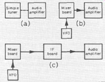
Figure 1 Build your Colt and watch it grow. A simple crystal set (a)
becomes a direct conversion receiver (b) and finally an 80 meter amateur
band superhet (c)

Figure 2 The Philips TDA7052 integrated circuit (IC) used in the audio
amplifier needs very few extra components. It has a signal voltage gain
of 100 times and the output is suitable for a loudspeaker or headphones
Description
The radio will be built in three modules, or stages, as illustrated in Figure 1.
Each of these is built on a printed-circuit board (PCB) or matrix board and can be tested in its own right. The case will need some holes drilled, and care will be needed to mount the PCBs in the case.
Get to it!
Surprisingly enough, when you are building a radio section by section (which is always the best way), it is easiest to start at the output and work towards the input, and you can test what you have done stage by stage. You will see what this means as you progress with your construction.
Every receiver needs some audio frequency (AF) amplification to make the sound signals big enough for you to hear. The circuit for the AF amplifier is shown in Figure 2. It uses the TDA7052 integrated circuit (IC) plus a handful of extra components. R1 in conjunction with C2 and C3 decouple the battery supply, preventing any audio signals getting through to it and affecting other parts of the radio, when they are connected. C1 acts to prevent high frequencies (above the 3 kHz bandwidth) going into the amplifier input. A volume control, VR1, is connected across the amplifier input, so that the amplifier can accept signal inputs over a wide range.
Figure 3c shows the connections, which are made with screened cable. The center conductor of the left lead goes to the point marked 'input' in Figure 2, the braid being connected to the amplifier earth (0V) tag. The right lead to VR1 goes to whatever signal source you have for testing -- see below. VR1 is not mounted on the PCB.
The circuit is constructed on a small PCB or matrix board. Make sure that the electrolytic capacitor, C3, is soldered into the board the correct way - its positive and negative connections are shown in Figure 3b for reference. If you are at all concerned about soldering the IC into the board, enlist some help, or , obtain an 8-pin DIL socket, which you can solder in and then carefully insert the chip into the socket, making sure that is the correct way round. The markings on the chip are shown in Figure 3a.
The output leads from the amplifier go to a plastic 6.3mm (1/4 inch) mono jack socket, so that neither output lead is connected to the metal case. The amplifier will drive a pair of headphones or a small 8 ohm loudspeaker.
The battery leads must be the right way round also; the battery itself can be a PP3 or PP9, or you can use a small DC power supply.
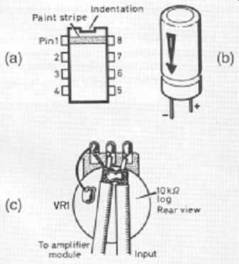
Figure 3 It is important to check the component connections carefully.
The diagram shows (a) top view of the IC, (b) electrolytic capacitor and
(c) volume control (VR1) connected across the input of the amplifier.
Testing
First, check that all the components are in the right places, that your soldering is good, and that you have headphones or a loudspeaker connected. Set VR1 about halfway along its travel. Connect the battery.
A slight hissing noise should be heard; touching the input lead to the amplifier (the center of the three connections on VR1) should produce a loud buzz. Touching the shaft at the same time will make the buzz quieter.
This is the quickest way of confirming that your amplifier seems to be working. The only real test is to give it something meaningful to amplify! See the design of our Crystal Radio Receiver for full details.
Parts list
Resistors: all 0.25 watt, 5% tolerance
R1 22 ohms
VR1 10 kilohms log
Capacitors
C1, C2 0.1 microfarad (uF)
C3 220 microfarads (uF) electrolytic 16V
Integrated circuit
IC1 TDA7052 audio amplifier
Additional item
PCB (see below)
Component suppliers:
Digikey
The next part . . .
The metal case will be marked out ready to receive the completed modules.