AMAZON multi-meters discounts AMAZON oscilloscope discounts
Introduction
Here's a quick project to fill in a winter's evening! It was originally designed as a piece of test gear for the Colt receiver, but can be successfully used by anyone as a first radio project. Another use for it would be as test gear for any audio amplifier project requiring an audio input for test purposes; this is ideal, as it does not require any power supply!
Details
The initial rough-and-ready test for the audio amplifier of the Colt receiver will have whetted your appetite; you will want to prove more conclusively that your amplifier works, and in a way that others in the household will appreciate. Buzzing noises are not convincing in this respect! You are going to put together a simple crystal set - the simplest type of radio that there is -- and use it as a signal injector for your amplifier. In this way, you build a real medium-wave (MW) receiver which drives a loudspeaker, as an intermediate product of the construction of an 80 meter amateur band receiver! The circuit diagram is shown in Figure 1. It has a 60-turn coil mounted on a small piece of paper or card wrapped round a ferrite rod. The coil has a connection made to its center-tap (the middle turn of the coil). The tuning capacitor, VC1, is the most expensive part of the circuit but don't worry, it will be used in the final design of the receiver also! Connect the diode, D1, from the center-tap to the input to the potentiometer of the amplifier circuit of the Colt. Be careful to connect the aerial to the vanes of VC1, and not to its frame, or you will experience some strange effects when you are tuning.
If your amplifier is working correctly, you should be able to receive local stations on medium-waves quite well.
If you think the crystal set will be of use to you in the future as a signal injector, all you will need will be another variable capacitor! If you do not intend to use the amplifier, a small crystal earpiece will allow you to listen.
Walkman-type headphones will not work!
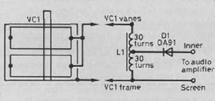
Figure 1 Both sets of moving vanes are joined as shown. L1 is wound on a
ferrite rod with 32 SWG wire and center-tapped. A single winding (no tap)
can be used, joining D1 to the top of the winding.
Parts list
Variable capacitor: VC1 125 + 125 picofarads (pF) twin-gang
Ferrite rod: About 100mm to 140mm long
Diode: D1 OA91 germanium diode
Additional items:
Wire: 2m of enameled copper wire, between 23 SWG and 32 SWG
Earpiece: High-impedance crystal type (only needed if you are not using the amplifier)