AMAZON multi-meters discounts AMAZON oscilloscope discounts
Introduction
The ZN415E integrated circuit (IC) can be used to make a very efficient AM portable MW broadcast radio with a built-in loudspeaker. Here's how!
The circuit
Figure 1 shows the circuit diagram of the portable radio. It's not as complicated as it may appear, especially after you have got started. L1 is a coil of wire mounted on a ferrite rod, acting as an aerial; VC1 is a variable capacitor which works, with L1, to tune in different stations. IC1 contains circuits of its own which boost the selected signal and it includes a detector which extracts the audio signal from the incoming RF signal. Earphones could be connected to the output of IC1 (between pins 4 and 5), but the output would not be powerful enough to drive a loudspeaker.
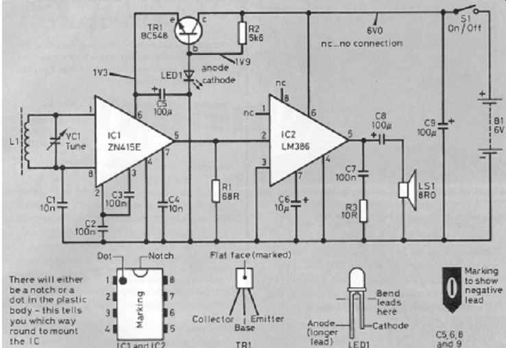
Figure 1 The circuit diagram of our easy-to-build portable radio. Take care
to mount the ICs and LED the correct way round
More sound
This is where IC2, an LM386 comes in. This is a small audio power amplifier which produces audio signals with enough power to drive a small loudspeaker, LS1. The radio uses a 6 volt battery, which is made by connecting four 1.5 volt AA cells in series (4 × 1.5V = 6V) using a battery holder designed for this purpose. Although a 6V supply is ideal for IC2, it is far too great for IC1, which needs only about 1.3V. This lower voltage is provided from the 6V supply by TR1 (an npn transistor), R2 and LED1 (a light-emitting diode). When current passes through an LED (see the description of the LED in this series) a reasonably constant voltage of 1.9V appears between the anode and the cathode. Because of the voltage (0.6V) that always exists between the base and emitter of a working transistor, the voltage on the emitter is about 1.9V - 0.6V = 1.3V, and this is used as the power supply for IC1.
To keep the radio as simple as possible, no volume control has been fitted.
Instead, you can use the directional properties of the ferrite rod aerial (see the information on ferrites in this guide) to reduce the volume by rotating the set about a vertical axis using the handle provided.
Putting it all together
1. Start by covering the ferrite rod with Sellotape, or alternatively wrap a piece of paper tightly around it, and secure it with Sellotape. Then, with at least 2 meters of 24 SWG enameled copper wire, wind 75 turns tightly around the rod. To be safe, leave about 50mm of wire at the ends of the coil, then wrap the whole coil with Sellotape to hold the turns in place, leaving only the ends free. Then, using a small piece of sandpaper, remove the enamel from the last centimeter of each end of the coil.
2. Most of the components are mounted on a piece of Veroboard (the type with parallel copper strips on one side). The piece used on the prototype measured 32 holes by 10 strips, as Figure 2 shows. Before you start fitting components, cut the copper strips as shown. It is easier to do it now than when the board is littered with components! The strips may be cut with a 3mm (1/8 inch) twist drill rotated between thumb and forefinger. Resist the temptation to use a hand drill - the idea is just to cut the copper, not to drill right through the board!
3. Solder the IC sockets and the other components on the board as shown in Figure 2. Make sure that the IC sockets are fitted with their notches towards the top of the board, as viewed in Figure 2. Do not insert the chips yet. Always keep the wires left over from cropping resistors and capacitors, they will come in handy at times like this: make the wire links that are clearly shown in Figure 2. Connect the electrolytic capacitors (C5, C6, C8 and C9), the transistor and the LED the correct way round; then check it again when you have done it!
4. Finally, solder lengths of stranded insulated wire to act as 'flying leads' for future connection to L1, VC1, LS1, S1 and the battery connector.
5. Apart from the battery holder, everything is mounted on the case lid.
This makes assembly and testing much easier, and eases fault-finding if the need arises! At the speaker position, make one large hole or a series of small holes to let the sound out. The ferrite rod may be stuck to the lid, as may the loudspeaker. Drill holes of the correct size to fit the particular types of variable capacitor (VC1) and switch (S1) that you are using. The Veroboard may be held in position by Blu-Tack or double sided sticky tape.
6. Before inserting IC1 and IC2, connect the battery and switch S1 on. The LED should glow dimly (you may have to shield it with your hand in order to see it). If you have a test meter, check that there is about 1.3V between pins 6 and 4 of IC1. If the reading is around 6V or there is no glow, you may have connected the LED the wrong way round! When everything seems normal, switch off and disconnect the battery. Insert IC1 and IC2, making sure that the pins are straight and lie immediately above their corresponding holes in the sockets, and that the notches line up with the notches in the holders. Then push gently downwards on each IC in turn until the chip is firmly seated in its socket.
7. Switch on! By rotating the tuning capacitor, VC1, you should now be able to tune in many stations, rotating the radio to give you some volume control.
Figure 2 Veroboard layout for the Portable Radio. Make sure that all the wire links are included
Final touches . . .
The handle was made with part of an old leather belt, secured to the case with 'number plate' nuts and bolts from Halfords. The loudspeaker grille is the lid from a pot-pourri container, and some extra holes were drilled in the back to improve the sound. See what you can find to finish off your radio!
===========
Parts list
You should get used to using the 'beg, borrow or steal' technique, or to use your ever-expanding junk box.
Resistors: all 0.25 watt, 5% tolerance
R1 68 ohms
R2 5.6 kilohms
R3 10 ohms
Capacitors:
C1, C4 10 nanofarads (nF) or 0.01 microfarad (uF) ceramic
C2, C3, C7 100 nanofarads (nF) or 0.1 microfarad (uF) ceramic
C5, C8, C9 100 microfarads (uF) electrolytic, at least 10V
C6 10 microfarads (uF) electrolytic, at least 25V
Semiconductors:
IC1 ZN415E radio chip
IC2 LM386 audio power amplifier
LED1 3mm green LED
TR1 BC548 npn transistor
Additional items:
LS1 Miniature 8 ohm loudspeaker
S1 Miniature SPST toggle switch
Ferrite rod Length approx. 100mm
24 SWG enameled copper wire
VC1 Tuning capacitor 140 to 300 picofarads (pF)
Tuning knob
8-pin DIL IC sockets (two required)
4 × AA-size battery holder (long)
PP3-type clip for battery holder
Plastic box approx. 158 × 95 × 54mm
0.1 inch Veroboard, min. size 32 holes × 10 strips
Plus:
Stranded insulated conductor for flying leads
Multicore solder
Materials for handle and speaker grille
Double-sided sticky tape or Blu-Tack
Sellotape
Glue
Four AA-size 1.5V batteries