AMAZON multi-meters discounts AMAZON oscilloscope discounts
Introduction
Many of the circuits for receivers and transmitters presented in this series rely upon the variable capacitor as a means of tuning. Another method of varying capacitance (without any moving parts) is provided by the varactor diode, sometimes called a varicap diode. This is a component which changes its capacitance as the voltage across it is varied.
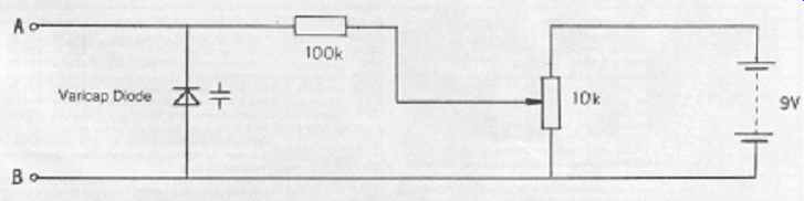
Figure 1: The capacitance of the varicap diode (between A and B) increases
as the voltage is reduced, using the variable resistor
The details
Figure 1 shows how a varactor diode might be connected to demonstrate its operation. Its symbol is that of an ordinary diode, with a capacitor symbol next to it. A variable voltage is applied across it in such a way that the diode is reverse-biased. This means that virtually no current passes through it - the positive voltage is applied to the cathode. Varactors are cheaper than variable capacitors, and they are tiny in comparison, very suitable for today's miniature circuits. If A and B were connected across the tuning coil in a simple receiver (with a series capacitor to block the DC from the battery reaching the coil), the tuning operation would be accomplished by turning the knob on the 10 kilohm potentiometer.
Varactors are available with different values, from less than 20 picofarad (pF) for VHF applications to 500 pF for medium-wave radios. They are tuned usually by voltages between 2V and 9V. For a real application of varactors, you should consult the circuit diagram of the Yearling 20 meter receiver, elsewhere in this guide.
In some circuit designs, several circuits are all tuned to the same frequency in order to improve the overall selectivity (the ability of the circuit to reject signals very close in frequency to the wanted signal). Special dual- and triple-varactors are available for circuits like this. Having been made at the same time from the same materials makes their individual characteristics virtually identical. Like all other diodes, they must be correctly wired into the circuit - their polarity is important.
Changes in temperature will cause the capacitance to change which, if it were part of an oscillator circuit, would cause the oscillator to drift - you would have to keep retuning the radio! This can be corrected by using a special integrated circuit called a phase-locked loop (PLL). Modern TV sets and satellite receivers use varactors and PLLs in this way.
Some useful varactor types
Type No. Tuning range
pF/V pF/V
Description
BB204B 42/2.0 15/12 Dual VHF
BB212 560/0.5 22/8 AM tuning
KV1235 450/2.0 30/8.5 Triple AM
KV1236 450/2.0 30/8.5 Dual AM
MV1404 120/2.0 9/10.0 HF tuning