AMAZON multi-meters discounts AMAZON oscilloscope discounts
Introduction
We usually think of a transmitter as being a 'black box'. However, that is the form a transmitter takes for our use on the amateur bands. Many electrical circuits are transmitters, even though transmitting may not be their primary function!
Anything that emits electromagnetic energy at any frequency is a transmitter, from radio at the low-frequency end of the spectrum, to gamma rays at the high-frequency end. We all know that a magnet will attract certain metals and that a comb rubbed on your coat sleeve will pick up small pieces of paper. The former is an example of the effect of a magnetic field, the latter of an electric field. Electromagnetic fields are combinations of both types of field, and are produced whenever an electromagnetic wave is transmitted.
What frequency?
Many everyday objects have a natural frequency of oscillation. This is called their resonant frequency. A wine glass will ring when struck gently; an empty wine bottle will sound if you blow across the top; a guitar string will vibrate when plucked. These are all examples of resonance, and the resonant frequencies will not change unless the objects themselves are changed physically in some way. These are resonances in sound; we are primarily interested in electrical resonances.
The basic electrical resonant circuit is the combination of an inductor (coil) and a capacitor, as shown in Figure 1.
A pulse of energy applied to this tuned circuit will make it ring (oscillate) at its resonant frequency. The energy in the circuit transfers between the inductor and the capacitor every cycle of the oscillation. Just like the wine glass, its oscillation dies away because it is losing some energy to its surroundings -- it is transmitting! The frequency of the resonance depends on the values of L and C.
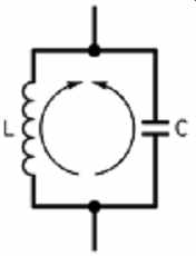
Figure 1 The basic electrical resonator. The energy in the circuit alternates
between the inductor and the capacitor
Keeping it going
If we want to keep the circuit oscillating, rather than having it die away, we must supply the circuit with just enough energy to replace the energy lost both by radiation and by losses in the circuit itself. Because of this, you will find in all oscillator circuits, a transistor, valve or FET working with the tuned circuit to provide this extra energy.
As it stands, of course, even with its transistor, our oscillator will not radiate very far. Connecting an aerial to it, and a Morse key to interrupt the power supply, it would become a very low-power CW transmitter. Add a couple more transistors to form a radio-frequency (RF) amplifier, and you have the basis of a simple low-power (QRP) transmitter.
Resonant circuits can also be made using quartz crystals; these work at the crystal frequency only, and this is marked on the crystal case.
A tiny spark transmitter
This is a simple piece of test gear that will increase your knowledge and understanding of resonance. You can use it to estimate the resonant frequency of most of the inductor/capacitor (LC) tuned circuits that you build. The circuit is shown in Figure 2. It operates around a relay. Any relay that operates from a 6V to 9V source and has contacts which are normally closed (i.e. closed when the battery is not connected). Fit the relay, a toggle switch and the battery in a metal box, and connected up as shown in the diagram. Some foam rubber inside the box may help to reduce the escaping noise of the relay. A small hole in the side of the box enables the 2-turn loop to emerge. This should be about 40mm diameter, made with insulated wire.
Switch on; there should be a loud buzzing noise from the relay. If not, you have probably chosen the wrong contacts on the relay! When it is working, bring the loop close to the aerial of a radio -- it should produce a loud noise from the speaker!
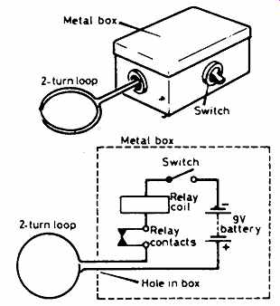
Figure 2 The current path is interrupted when relay is energized as shown
above
How it works
When you switch on, current flows through the relay contacts and through the relay coil. The relay operates and opens the contacts, causing the relay to 'drop out'. When it does, the circuit is completed again and the contacts are opened, and the cycle repeats. Each time the relay contacts open, there is a small spark between them, causing very rapid current surges through the wire loop. This makes the loop transmit RF energy, very briefly. In the early days of radio, this type of circuit was known as a spark transmitter .
Make a tuned circuit
Use a discarded toilet-roll center, and wind about 10 turns of enameled copper wire round it, keeping each turn close to the next. Scrape off the enamel for about 1 cm at each end, and solder a 100 picofarad (pF) capacitor (or a variable capacitor of about the same value) between the ends. The resonant frequency should be about 10MHz. If you have used fewer turns or a smaller capacitor, the frequency will be higher.
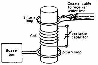
Figure 3 Experiment with the spacing between the loop and the tuned circuit
Measuring the resonant frequency
Set up the buzzer as shown in Figure 3, with the loop around one end of your coil. Then make a similar loop, solder it to the end of a piece of coaxial cable going to the aerial socket of a calibrated receiver. Set the buzzer going, tune the receiver around 10MHz, and search for the maximum noise level from the speaker. When you have found it, move the two loops as far away as possible from the main coil. This is called reducing the coupling between the coils, and it may result in a slightly different, but more accurate, resonant frequency.
Parts list
Any small relay which operates between 6V and 9V
Metal box -- do not use a plastic box!
9 volt battery and connector
On/off (SPST) toggle switch
Plastic foam, as required